

Learn Multi
platform Z80 Assembly Programming... With
Vampires!
Platform Specific Lessons
Platform Specific Lessons
<- Back to the Main
Contents & Basic Z80 Assembly Lessons
Platform Specific Series - Lets learn how the hardware of the systems work, so we can get it to do what we want... Covers Amsrad CPC,MSX,ZX Spectrum, TI-83,Enterprise 128/64 and Sam Coupe!
Making use of the SN76489 on different systems...
Detecting the CPC+ and RAM:
Memory Banks on the 128k ZX Spectrum
Contention
Rom and Ram banking
Rom and Ram banking are handled by two ports, &1FFD and &7FFD... because these ports do other things, we need to back up the other bits when we change them... for this purpose the system keeps a backup of the current state of these ports in memory
To select a bank of RAM at &C000, all we do is set bits 0-2 of &7FFD to a value 0-7... this will page the respective bank in at &C000
Rom Banking is possible by setting bit 2 of &1FFD and 4 of &7FFD... these bits make a number 0-4 which is the rom bank at &0000
+3 Banking
This is only possible on a black +2 or +3 spectrum...setting bit 0 of &1FFD to 1 turns on this mode, and the other bits purpose changes accordingly
There are 4 possible bank combinations, shown in the chart below:
Lets look at the details of these two commands:
EXOS Function 24 - Allocate Segment
This command will request another 16k segment... status reg will be Zero if succeeded, NZ if another full 16k is not available
If succeeded the segment number will be returned in C... if only a shared segment was available, the boundary will be in DE
Parameters: none
Returns: A=status C=segment number DE=EXOS boundary within this segment (if returned is a shared segment, otherwise &4000)
EXOS Function 25 - Free Segment
This command will free a 16K segment of RAM. The segment must have been allocated via EXOS function 24.
Using our Segments!
Detecting our system...64k, 128k or 256k
The Theory of Sprites
Continue to Page 4
Back to Page 2
Platform Specific Series - Lets learn how the hardware of the systems work, so we can get it to do what we want... Covers Amsrad CPC,MSX,ZX Spectrum, TI-83,Enterprise 128/64 and Sam Coupe!
Gameboy Color Registers
As with all other registers, The registers that control sound on the GBC are memory mapped, they're pretty easy to use, but there are a lot of them!
Channel 2 - Tone
As with all other registers, The registers that control sound on the GBC are memory mapped, they're pretty easy to use, but there are a lot of them!
| Section | Addr | Name | Bits | Bit Meaning |
| Sound | FF10 | NR10 - Channel 1 (Tone & Sweep) Sweep register (R/W) | -TTTDNNN | T=Time,D=direction,N=Numberof shifts |
| Sound | FF11 | NR11 - Channel 1 (Tone & Sweep) Sound length/Wave pattern duty (R/W) | DDLLLLLL | L=Length D=Wave pattern Duty |
| Sound | FF12 | NR12 - Channel 1 (Tone & Sweep) Volume Envelope (R/W) | VVVVDNNN | C1 Volume / Direction 0=down / envelope Number (fade speed) |
| Sound | FF13 | NR13 - Channel 1 (Tone & Sweep) Frequency lo (Write Only) | LLLLLLLL | pitch L |
| Sound | FF14 | NR14 - Channel 1 (Tone & Sweep) Frequency hi (R/W) | IC---HHH | C1 Initial / Counter 1=stop / pitch H |
| Sound | FF16 | NR21 � Channel 2 (Tone) Sound Length/Wave Pattern Duty (R/W) | DDLLLLLL | L=Length D=Wave pattern Duty |
| Sound | FF17 | NR22 - Channel 2 (Tone) Volume Envelope (R/W) | VVVVDNNN | C1 Volume / Direction 0=down / envelope Number (fade speed) |
| Sound | FF18 | NR23 - Channel 2 (Tone) Frequency lo data (W) | LLLLLLLL | pitch L |
| Sound | FF19 | NR24 - Channel 2 (Tone) Frequency hi data (R/W) | IC---HHH | C1 Initial / Counter 1=stop / pitch H |
| Sound | FF1A | NR30 - Channel 3 (Wave Output) Sound on/off (R/W) | E------- | 1=on |
| Sound | FF1B | NR31 - Channel 3 (Wave Output) Sound Length | NNNNNNNN | Higher is shorter - no effect unles C=1 in FF1E |
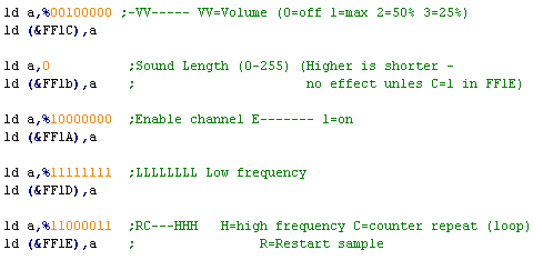
| Sound | FF1C | NR32 - Channel 3 (Wave Output) Select output level (R/W) | -VV----- | VV=Volume (0=off 1=max 2=50% 3=25%) |
| Sound | FF1D | NR33 - Channel 3 (Wave Output) Frequency's lower data (W) | LLLLLLLL | Low frequency |
| Sound | FF1E | NR34 - Channel 3 (Wave Output) Frequency's higher data (R/W) | RC---HHH | H=high frequency C=counter repeat (loop) R=Restart sample |
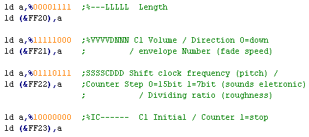
| Sound | FF20 | NR41 - Channel 4 (Noise) Sound Length (R/W) | ---LLLLL | L=Length |
| Sound | FF21 | NR42 - Channel 4 (Noise) Volume Envelope (R/W) | VVVVDNNN | Volume / Direction 0=down / envelope Number (fade speed) |
| Sound | FF22 | NR43 - Channel 4 (Noise) Polynomial Counter (R/W) | SSSSCDDD | Shift clock frequency (pitch) / Counter Step 0=15bit 1=7bit (sounds eletronic)/ Dividing ratio (roughness) |
| Sound | FF23 | NR44 - Channel 4 (Noise) Counter/consecutive; Inital (R/W) | IC------ | C1 Initial / Counter 1=stop |
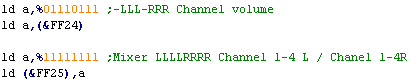
| Sound | FF24 | NR50 - Channel control / ON-OFF / Volume (R/W) | -LLL-RRR | Channel volume (7=loud) |
| Sound | FF25 | NR51 - Selection of Sound output terminal (R/W) | LLLLRRRR | Channel 1-4 L / Chanel 1-4R (1=on) |
| Sound | FF26 | NR52 - Sound on/off | A---4321 | read Channel 1-4 status or write All channels on/off (1=on) |
| Sound | FF30
� FF3F |
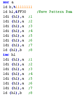
Wave Pattern RAM | HHHHLLLL | 32 4 bit samples |
| As
always,
we just need to write our data to the memory addresses
between &FF10-&FF3F to set the sound
options...Whatever you're trying to do Just don't forget to
turn the sound on with FF24 and FF25! If you're not using sound, turn off the channels with FF26 |
 |
Channel 2 - Tone
| Before we try to make any sounds, we need to set the system
volume, and turn on some sound channels! Each channel is turned on with a 1 bit for the left and right speaker, and the overall volume is 0-7 for each speaker. |
 |
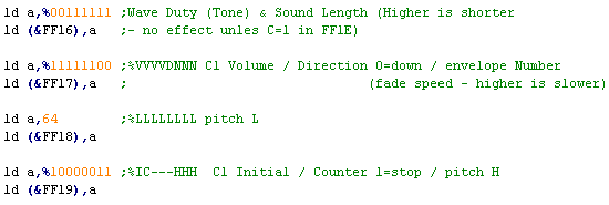
| The tone channels have a few configurable parameters...
Firstly (of course) is the tone, defined bt 11 bits in &FF18
and &FF19 We can also define a length, if we want, though it will not have any effect unless the Counter bit in FF19 is set to 1... there si something called the 'Wave Duty' which changes the shape of the tone, try it for different sounds We can also define a volume, and an Envelope, envelopes are just a 'fade' - 0 is off, 1 is fast, and 7 is slow... we can fade in or out depending in Direction and start volume We need to set the 'Initial bit' to 1 to actually start the sound! |
 |
Channel 1 - Tone & Sweep
Channel 3 - Wave
Channel 4 - Noise
| Channel 1 is basically thesame as Channel 2, but with an
extra 'Sweep funcion' The sweep function allows us to change the pitch of the sound over time... If we do not want this, we can simply set it to 0... however any other value will make the tone change over time, and lower values in T and N will make the tone change faster |
 |
Channel 3 - Wave
| If we're going to use the wave
channel, we need some sound data... The Wave channel uses 16 bytes, with 4 bits per sample... we need to fill the area &FF30-FF3F with some wave data to make a sound, |
 |
| Making the sound play is also
similar to the tone channels, however we have fewer options, Wwe only have 4 options for the volume, and we have no envelope we can use. |
 |
 |
The
Gameboy may have a 'Wave' Channel, but don't think that
you're going to be doing speech or anything... not with 32
samples! Check out Beatmania on the Gameboy, then look at the Wonderswan version... The Gameboy totally got it's ass handed to it by the WS didn't it! |
| If you
want to emulate AY, you can use the Wave channel as another
Tone channel... it's a bit of a pain, but it works ok! If you want to play digital wave files, check out this tutorial! |
 |
Channel 4 - Noise
| The Noise Channel has a lot in common with the Tone Channels Rather than a frequency, The Noise sound is defined by &FF22 ... SSSS is essentially the pitch... low numbers are white noise, high numbers are a low rumble... the Dividing ratio will change the roughness of the sound, making it sound less 'crisp'... We can aslo change the Counter step, which will make the noise sound eletronic, which may be depending on the effect you're trying to make As always, it's best to try different settings to get the sound you're after. |
 |
| Now we know
how to make the sounds work, we can easily write ChibiSound... We're not covering it here, but it's in the source code, so just go ahead and download it if you want to take a look! |
 |
Basics of the SN76489
The sound chip takes all its data from a
single 8 bit port...
The 7th bit is the 'latch bit' which tells the chip if a new command is being sent (1) or a second part of the last command (0)
Bits 6 and 5 are the channel number... 0-2 are tone chanels, 4 is the noise channel
Bit 4 is the 'Type bit'... 0 defines the sound... 1 defines the Volume
The purpose of the remaining bits (0-3) vary depending on the first 4
| Bits | |||||||||
| Command | Bit Details | 7 | 6 | 5 | 4 | 3 | 2 | 1 | 0 |
| Format Template | L=Latch C=Channel T=Type XXXX=Data | L | C | C | T | D | D | D | D |
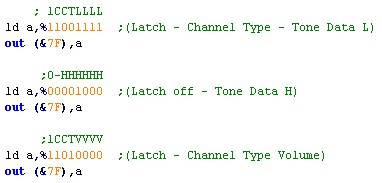
| Tone - Command 1/2 | C=Channel L=tone Low data | 1 | C | C | 0 | L | L | L | L |
| Tone - Command 2/2 | H= High tone data (Higher numbers = lower tone) | 0 | - | H | H | H | H | H | H |
| Volume | C=Channel (0-2) V=Volume (15=silent 0=max) | 1 | C | C | 1 | V | V | V | V |
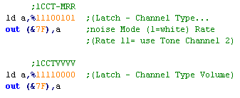
| Noise Channel | (Channel 3) M=Noise mode (1=white) R=Rate (3=use tone 2) | 1 | 1 | 1 | 0 | - | M | R | R |
Making a Tone
| To make a tone we will probably
want to send 3 bytes to the same channel The first one will define the Low 4 bits of the Tone (Latch will be 1) The second will be the High 6 bits (Latch will be 0) If we want to change the volume, we'll need to send a 3rd byte Volume is defined by 4 bits (0=max volume).. the Latch will be 1 - there is no second (latch0) byte for a volume command |
 |
Making a noise!
| Using the Noise channel is
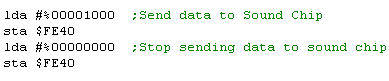
similar, though we send no second byte with the latch off.. We have 3 bits to control the nosie, bit 2 is the Mode - we can either have white noise (1) or eletronic nose (0) The Rate bits can be 0-2.... setting a rate of 3 will link the rate to the frequency of Tone Channel 2... if you do this you'll probably want to mute tone channel 2 by setting it's volume to 15 |
 |
Making use of the SN76489 on different systems...
| Whatever
the destination platform or CPU, the command data above will
work the same, however what we need to do to send that data
to the sound chip will vary... lets take a look at how to get our command data to the sound chip on various systems that use it! |
|
  |
The
Mastersystem and GameGear The examples above were from the Mastersyem! On the SMS/SGG we just send all our data to port &7F! |
 |
 |
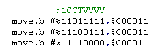
The Sega Genesis / Megadrive If we're getting the Genesis Z80 to control the SN76489, we can just send data to port &7F again! Unlike the NeoGeo, we can access the sound chip from the 68000 - which is probably easier!... we do this by writing to port &C00011 The data we send is identical to the SMS/GG - but the 'White Noise' generated by the Genesis is lower pitch, so you may need to change the frequencies you use for noise. |
 |
 |
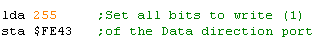
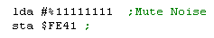
The BBC Micro The Sound Chip shares a port with the keybord... Before we can send any data to the sound chip, we have to set the port to WRITE... we do this by writing 255 to address $FE43 (we only do this once) Once we've done that, we can write our data to $FE41 in the same way as the examples above! |
   |
| Chibisound
is
just for Beeps and SFX... if we wanted to do proper music on
the Genesis, it would be best to use the Z80... we could even
use ArkosPlayer! Then again, we'd probably want to use the YM2612 sound chip instead! |
|
|
Not
impressed by a few beeps... Well Fine! Check out this
tutorial, It'll teach you how to play wave files and digital
sample |
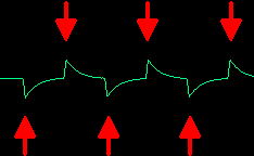
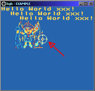
| The Beeper is the worst possible sound system! but we can make
something out of it!... with just one bit controling the
sound... we can 'blip' the sound - which has the effect of
sending a pulse to the beeper (shown by the red arrows to the
right) By altering the time between these 'blips' we can affect the pitch of the resulting tone!... the upside is we can make a good range of tones... the downside is, we don't have any volume control... and we'll pretty much have to use all our CPU power calculating the delay between the 'blips' re-sounding the blips... This means, unlike the other options, sound will not play during normal operation... which is why background music isn't really a thing on the ZX Spectrum 48k! If we want to make a distorted noise, that's pretty easy too... all we need to do is 'randomly' skip some of the 'blips'... the tone will sound rough and destorted as a result! |
 |
 |
Really, we're having to
create the waveform ourselves here by creating high and low
peaks... it's a real pain to do, but if you're very clever you
can do some impressive stuff! There is some sourcecode online for some speccy 'music players' online that can play 'proper' multi-channel music using the beeper speaker if you really want to push the 48k systems to the max! |
 |
ZX Spectrum 48k & Beeper- The various uses of Port &FE! |
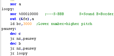
| Port FE on the speccy controls the border, tape (Mic) and
Beeper sound The "Beeper" sound chip is incredibly crude... it is controlled by bit 4 of the port &FE... by turning it on and off we can make simple sounds... See the example to the right... by changing the pause (caused by BC) we can change the pitch of the sound... 3000 will be a relatively low pitch... 500 will be higher... Some clever programs even manage to "Fake" multiple sound channels! The big disadvantage to all this is that the CPU will be busy during the whole time, so the Beeper chip isn't very helpful, and we'll want to use the AY sound chip on the 128k systems... but on the 48k machines, it's all we've got! |
 |
 |
Beeper sound on the Apple II |
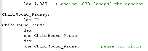
| The principle on the Apple II is
the same, however instead of writing bits to a port, we simply
READ from $C030 The beeper hardware is connected to memory address $C030... and reading from $C030 has the effect of causing the Beeper to flip the wave... it's weird that we read not write..., but that's what we do! Each time we do, it will flip the sound wave, again we need to wait a while depending on the frequency, then loop the operation to keep the sound playing! |
 |
|
When we
want to make a noise, we need some random data! On the speccy Chibisound uses the R register... on the Apple, it uses the sourcecode of the program itself as a pseudorandom source.... All we need to do is skip some of the 'blips' depending on a bit of the random data... it will make the sound more rough! |
| Ever heard
the speech samples on those old games? you can do that too! Playing wave files is pretty easy... see here |
|

The Gate Array!
Ram And Rom banking is handled on the CPC by the Gate array is at port &7Fxx... It has multiple purposes depending on the top two bits passed in the C byte
We'll need it on the CPC to bankswitch RAM, and CPC+ to access cartrige ROM!
Ram banks on the CPC
Ram And Rom banking is handled on the CPC by the Gate array is at port &7Fxx... It has multiple purposes depending on the top two bits passed in the C byte
We'll need it on the CPC to bankswitch RAM, and CPC+ to access cartrige ROM!
| 7 | 6 | 5 | 4 | 3 | 2 | 1 | 0 | Name | Bit meanings |
| 0 | 0 | - | B | P | P | P | P | Palette selection | B=Border P=Pen (0-3 / 0-15) |
| 0 | 1 | - | C | C | C | C | C | Palette color selection | C= Clolor number (0-26) |
| 1 | 0 | - | I | H | L | M | M | Rom / Mode | I= Interrupt mode H=High rom bank L=Low rom bank M=screen mode |
| 1 | 1 | B | B | B | R | R | R | Ram Bank | R = Ram config B= Bank number (0=128k 1+2=256k etc) |
Ram banks on the CPC
By default the Amstrad CPC has 64k or
128k, but it can actually support up to 576k!... since we can only
address 64k of ram we have to page in part of the extra memory into
the normal address space,
We do this by OUTing a byte from &C0-&FF to port &7F...
If we try to turn on an extra bank on a 64k machine, nothing will happen
If we try to turn on a 192k bank (C9-CF) on a 128k machine, we will get the equivalent 128k bank
We can use these facts to detect the amount of memory!
We do this by OUTing a byte from &C0-&FF to port &7F...
If we try to turn on an extra bank on a 64k machine, nothing will happen
If we try to turn on a 192k bank (C9-CF) on a 128k machine, we will get the equivalent 128k bank
We can use these facts to detect the amount of memory!
| 64K | 128K | 192K | And so on! | ||||||||||||||
| Area | C0 | C1 | C2 | C3 | C4 | C5 | C6 | C7 | C8 | C9* | CA | CB* | CC | CD | CE | CF | D0-FF |
| &0000 | RAM_0 | RAM_0 | RAM_4 | RAM_0 | RAM_0 | RAM_0 | RAM_0 | RAM_0 | RAM_0 | RAM_0* | RAM_8 | RAM_0* | RAM_0 | RAM_0 | RAM_0 | RAM_0 | ... |
| &4000 | RAM_1 | RAM_1 | RAM_5 | RAM_3 | RAM_4 | RAM_5 | RAM_6 | RAM_7 | RAM_1 | RAM_1* | RAM_9 | RAM_3* | RAM_8 | RAM_9 | RAM_10 | RAM_11 | ... |
| &8000 | RAM_2 | RAM_2 | RAM_6 | RAM_2 | RAM_2 | RAM_2 | RAM_2 | RAM_2 | RAM_2 | RAM_2* | RAM_10 | RAM_2* | RAM_2 | RAM_2 | RAM_2 | RAM_2 | ... |
| &C000 | RAM_3 | RAM_7 | RAM_7 | RAM_7 | RAM_3 | RAM_3 | RAM_3 | RAM_3 | RAM_3 | RAM_11 | RAM_11 | RAM_11 | RAM_3 | RAM_3 | RAM_3 | RAM_3 | ... |
* Bank mode C9 and CB may not work on all
hardware - it depends on the memory upgrade.
Turn on the CPC Plus:
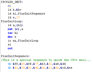
| We've covered it before, but remember, by default The CPC+
features are disabled, leaving us with only a regular CPC... to
use the PLUS features, we need to send a series of 17 bytes to
the CRTC at port &BCxx Once the CPC+ features are on, a special bank of 16k 'ASIC' memory will become available, which we can write to between &4000-&7FFF in the same way as our normal memory. To Turn it on we use: ld bc,&7fb8 out (c),c To turn it off we use: ld bc,&7fa0 out (c),c NOTE: When using the ASIC memory, We should make sure that we're using the 128k banks are disabled, or it can cause problems with some 128k ram upgrades. Mode C1/C3 are OK to use as they page in at &C000 |
 |
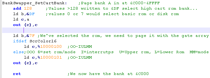
ASIC RAM and Cartridge
ROM on the CPC+:
|
Asic Ram, when enabled appears
at &4000-&7FFF, but we also have cartridge ROM
On a CPC+ the Cartrige ROM has 32 banks... numbered 0-31... Banks 0-7 are intended to act as system ROM, appearing between &0000-&3FFF... however ANY bank (0-31) can be paged in at &C000-&FFFF - the same area as screen memory! Even better, if we WRITE to this area - it will be written to the screen RAM through the rom, so we don't need to page out the ROM to write data to the screen! Setting a rom bank is easy, we write the ROM we want to port &DF... values 0-7 will set the Low rom area number... setting the High rom area is done by adding 128 to the rom we want, and OUTing it to &DF Once we've selected it we still need to enable the rom, and we do this by writing to Bit 3 of the Gate array! |
 |
| To detect
a CPC Plus, we send the PLUS sequence, and turn on the ASIC
ram.. .if nothing happened we don't have a CPC+... we can
use this fact to detect a CPC! |
|
|
While you can write
to ASIC ram just like normal memory, don't rely on being able
to read from it! The development of ChibiAkumas ran into a problem, because reading the CPCPlus interrupt line from the ASIC worked on emulators... but not real hardware! It's probably best to assume you can't read back any writable ASIC values! |
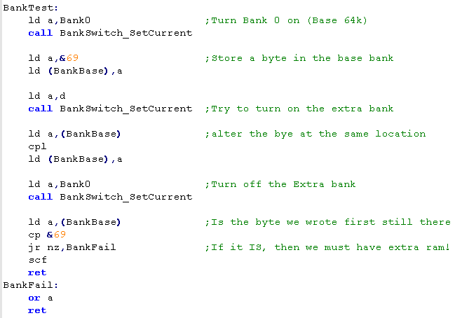
Detecting the CPC+ and RAM:
| So to detect RAM and the PLUS
ASIC, we need to set a byte in our normal memory, turn on the
feature (RAM or ASIC)... and WRITE to the same location - then
turn off the feature... If the byte we wrote isn't there, then we know the feature does not exist! In this code we'll use &69 as a byte that we'll write to the test location, and CPL to flip the bits of the location when we test. |
 |
Hardware and Ram detection:
| While each system is different
We're going to use a fairly generic detection function... It will return a value in DE... where D is the hardware type and E is the memory available On the CPC, D will be 1 if the machine is a PLUS, and E will be 0,1 or 2 depending if the machine is 64k,128k or 256k It's intended this function is executed at the start of your program, so the game can switch to different functions (or even load a different version of the game) depending on the platform. |
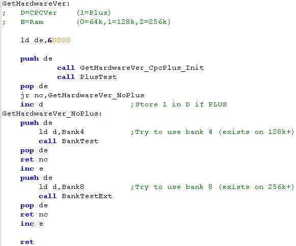 |
|
We'll be creating similar functions on all our other systems, but the data returned will be different, because there's no such thing as a Gameboy with ASIC ram or 512K... or a CPC with an 8mhz GBZ80 CPU! |

The Theory...
Brace yourself!
MSX Banks, Slots and Subslots... Oh my!
The MSX memory layout is far more advanced and powerful than other 8 bits... unfortunately that tends to just mean that it's more annoying!
Take a look at an MSX! You'll see it has 1 or usually 2 cartridge slots... right?... well actually there are two extra slots! 0 and 3 are 'internal' slots used by the system itself... so we have slots 0-3... simple right... actually no!
A 'Slot' can (but is not always) be split into 4 subslots... also numbered 0 to 3
EVERYTHING is in a slot, so RAM and ROM are in a slot somewhere... but unfortunately they aren't in the same place on all machines!... Slot 1 and 2 are always the cartridge slots, but the RAM could be in slot 3, or in slot 0-2 (slot 0 subslot 2)
It's all quite annoying!
The MSX memory map is split into 4 16K chunks, and each bank can be 'pointed' to one of the 3 slots... If the slot is expanded, each of these banks can be set to a different subslot... so bank 0 can point to 0-0 (slot 0 subslot 0), and bank 1 can point to 0-2 (slot 0 subslot 2)... while banks 2 and 3 could point to slot 3!
It needs to be understood that each slot has 4 banks for a full 64k - so when bank 0 and 1 points to slot 3-0... they are different 16k chunks... also in this case it is not possible to swap them round... Bank 0 (&0000-&3FFF) of the Z80 memory cannot point to bank 1 (&4000-&7FFF) of the Slot
So suppose we have the following set up:
Z80 Banks
The Z80 address range is split into 4 banks of 16k (also known as pages)
We may see a systems setup at boot in the following... Remember Slot 3-0 will have 4 different memory banks, but they can only be mapped into the matching positions of the Z80 address range.
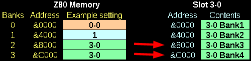
*** We can only map a Z80 bank to the MATCHING slot bank!
Slot Selection Register
Which Slot the Z80 will see in each bank is defined by the slot selection register at port &A8... it's 8 bits define all 4 banks slot number... each 2 bits define the slot number for an area of the address range
Sub-Slot Selection
Not all slots are expanded.... but it's easy to tell if they are, on boot addresses &FCC1-&FCC4 will be configured to record if slots 0-3 are expanded... the top bit (bit 7) will be 1 if they are.
If a slot IS expanded... there will be a memory mapped register at memory address &FFFF
The format is the same as the slot selection register
Detected Expanded slots!
The Subslot register won't exist at &FFFF if the slot is not expanded, so we need some way to detect if it is, fortunately, the firmware does this for us, and sets 4 memory locations accordingly... the top bit (bit 7 will be 1 if the slot is expanded
Memory Mappers
As mentioned, we can only map a bank of ram in a slot to the matching bank in the Z80 range... wouldn't it be nice if we could map a bank of ram to ANY bank of the Z80 range?
Well actually we can!... in theory!
A slot CAN have something called a 'Memory Mapper'... what's this? well it allows exactly what I just mentioned... any one of the 16k banks in the slot can be mapped to the that slots position... we still need to map in the slot (and subslot if required) but that slot can expose any bank of memory... this also allows us to address more than 64k... we can have up to 512k!
We select a slots memory mapping using 4 ports... note we can only write to these - we cannot rely on reading from them
A system may have more than one Memory mapper...one internal, and one
in an upgrade... but they will all set at the same time with these
ports... we will still need to page in the slot-subslot using the
usual method to get access to the memory.
So Memory mappers are more flexible, and allow more memory... what's not to like?.... well almost NO MSXes have them... even with the MSX2+, most MSXes do not have them... so unless your game is Turbo-R only, you're not going to be able to use them!
Cartridge Mappers
Cartridges also have 'mappers'... though they work differently - we just WRITE the bank number to a special address in the ROM, and the ROM will switch it's bank for us!
There are various mappers, but we'll look at "Konami with SCC" (Konami5) , it provides 4 rom areas that can be reconfigured - note they do not cover the whole Z80 range - as the bottom bank is assumed to be ROM, and the top bank is assumed to be RAM
Minimum MSX configurations
So what can we expect from our MSXes memory wise, well here's what you need to assume you'll have!
Soooo.... Effectively on the MSX1 we're pretty much going to have to
rely on using Cartridge ROM, and we won't be able to use a Memory
Mapper unless we're using the Turbo-R as the minimum requirement.
Practical Application... Finally!
Remembering the default slot layout
Slot Switching
Getting to our memory!
We can't be sure where our memory will be on any unknown MSX our game runs on, we can't even be sure all 64k is in the same slot!
If our game is in ROM, we probably only want to use the &C000-&FFFF area as RAM, because that's all most MSX1 systems have,
but if our game is for the MSX2 and we want to use all 64k We need to find a way to locate our RAM so we can use it!
Finding Memory on Disk Systems
Finding Memory on Non-Disk Systems
Detecting MSX version
The need for SPEED!
Finding a BankSwapper
|
The
Theory of MSX slots is complex and annoying! It's probably best to just ignore them!!! If you're game is on cartridge, just make do with 16k of ram at &C000 - as that's all MSX1 machines have... if your game is MSX2 on disk, Just use THIS |
MSX Banks, Slots and Subslots... Oh my!
The MSX memory layout is far more advanced and powerful than other 8 bits... unfortunately that tends to just mean that it's more annoying!
Take a look at an MSX! You'll see it has 1 or usually 2 cartridge slots... right?... well actually there are two extra slots! 0 and 3 are 'internal' slots used by the system itself... so we have slots 0-3... simple right... actually no!
A 'Slot' can (but is not always) be split into 4 subslots... also numbered 0 to 3
EVERYTHING is in a slot, so RAM and ROM are in a slot somewhere... but unfortunately they aren't in the same place on all machines!... Slot 1 and 2 are always the cartridge slots, but the RAM could be in slot 3, or in slot 0-2 (slot 0 subslot 2)
It's all quite annoying!
The MSX memory map is split into 4 16K chunks, and each bank can be 'pointed' to one of the 3 slots... If the slot is expanded, each of these banks can be set to a different subslot... so bank 0 can point to 0-0 (slot 0 subslot 0), and bank 1 can point to 0-2 (slot 0 subslot 2)... while banks 2 and 3 could point to slot 3!
It needs to be understood that each slot has 4 banks for a full 64k - so when bank 0 and 1 points to slot 3-0... they are different 16k chunks... also in this case it is not possible to swap them round... Bank 0 (&0000-&3FFF) of the Z80 memory cannot point to bank 1 (&4000-&7FFF) of the Slot
So suppose we have the following set up:
| Subslots | ||||
| Slot 0 | 0-0 | 0-1 | 0-2 | 0-3 |
| Slot 1 | 1 | Unexpanded slot | ||
| Slot 2 | 2-0 | 2-1 | 2-2 | 2-3 |
| Slot 3 | 3-0 | 3-1 | 3-2 | 3-3 |
| ROM | |
RAM | |
Cartridge | |
Empty |
Z80 Banks
The Z80 address range is split into 4 banks of 16k (also known as pages)
We may see a systems setup at boot in the following... Remember Slot 3-0 will have 4 different memory banks, but they can only be mapped into the matching positions of the Z80 address range.
*** We can only map a Z80 bank to the MATCHING slot bank!
Slot Selection Register
Which Slot the Z80 will see in each bank is defined by the slot selection register at port &A8... it's 8 bits define all 4 banks slot number... each 2 bits define the slot number for an area of the address range
| Port &A8 Bits | 7 | 6 | 5 | 4 | 3 | 2 | 1 | 0 |
| Bank number | 3 (&C000-&FFFF) | 2 (&8000-&BFFF) | 1 (&4000-&7FFF) | 0 (&0000-&3FFF) | ||||
Sub-Slot Selection
Not all slots are expanded.... but it's easy to tell if they are, on boot addresses &FCC1-&FCC4 will be configured to record if slots 0-3 are expanded... the top bit (bit 7) will be 1 if they are.
If a slot IS expanded... there will be a memory mapped register at memory address &FFFF
The format is the same as the slot selection register
| Subslot 0 &FFFF Bits | 7 | 6 | 5 | 4 | 3 | 2 | 1 | 0 |
| Subslot number | 3 (&C000-&FFFF) | 2 (&8000-&BFFF) | 1 (&4000-&7FFF) | 0 (&0000-&3FFF) | ||||
| We need to
check if a slot is expanded before we write to &FFFF...
also remember that this register only exists in subslot 0...
so we need to page in subslot 0 to Bank 3 before we can
change it! |
|
The Subslot register won't exist at &FFFF if the slot is not expanded, so we need some way to detect if it is, fortunately, the firmware does this for us, and sets 4 memory locations accordingly... the top bit (bit 7 will be 1 if the slot is expanded
| Slot | Address |
| 1 | &FCC1 |
| 2 | &FCC2 |
| 3 | &FCC3 |
| 4 | &FCC4 |
Memory Mappers
As mentioned, we can only map a bank of ram in a slot to the matching bank in the Z80 range... wouldn't it be nice if we could map a bank of ram to ANY bank of the Z80 range?
Well actually we can!... in theory!
A slot CAN have something called a 'Memory Mapper'... what's this? well it allows exactly what I just mentioned... any one of the 16k banks in the slot can be mapped to the that slots position... we still need to map in the slot (and subslot if required) but that slot can expose any bank of memory... this also allows us to address more than 64k... we can have up to 512k!
We select a slots memory mapping using 4 ports... note we can only write to these - we cannot rely on reading from them
| Port | Z80 Address range | Default value |
| &FC | &0000-&3FFF | 3 |
| &FD | &4000-&7FFF | 2 |
| &FE | &8000-&BFFF | 1 |
| &FF | &C000-&FFFF | 0 |
So Memory mappers are more flexible, and allow more memory... what's not to like?.... well almost NO MSXes have them... even with the MSX2+, most MSXes do not have them... so unless your game is Turbo-R only, you're not going to be able to use them!
|
Some
MSX memory mappers can be read from, but others can't... so
don't do it! Remember what you wrote back last time, if you need to know! also remember, that a Turbo-R with a MegaFlashRom will have TWO mappers... they both share the same ports, so it just depends what slot is in each bank when it comes to what the Z80 will see! |
Cartridge Mappers
Cartridges also have 'mappers'... though they work differently - we just WRITE the bank number to a special address in the ROM, and the ROM will switch it's bank for us!
There are various mappers, but we'll look at "Konami with SCC" (Konami5) , it provides 4 rom areas that can be reconfigured - note they do not cover the whole Z80 range - as the bottom bank is assumed to be ROM, and the top bank is assumed to be RAM
| Area | Z80 Address Range | Write Address to change bank |
| 1 | &4000-&5FFF | &5000 |
| 2 | &6000-&7FFF | &7000 |
| 3 | &8000-&9FFF | &9000 |
| 4 | &A000-&BFFF | &B000 |
Minimum MSX configurations
So what can we expect from our MSXes memory wise, well here's what you need to assume you'll have!
| System | MSX1 | MSX2 | MSX2+ | Turbo-R |
| Memory | 16k | 64k | 64k | 256K |
| Disk System? | NO | NO (sometimes) | NO (usually - not always) | YES |
| Mapper? | NO | NO | NO (sometimes) | YES |
Practical Application... Finally!
Remembering the default slot layout
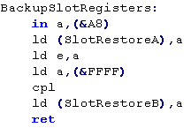
| When our game starts, we should
backup the current configuration of the Rom and RAM, we do
this by reading IN port &A8 to get the slot config... and
memory address &FFFF to get the subslot configuration...
although we do need to flip the bits of the data in address
&FFFF |
 |
|
It's wise to backup the default slot layout, as you will need to restore it if you need to use the firmware later to do jobs like disk access... just run the commands above as soon as your program runs, and save the two bytes needed to restore things for later! |
Slot Switching
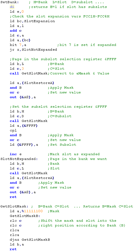
| We're going to use a generic
function for setting our Slot and Subslot into one of the Z80
banks of memory... Because the slot/subslot registers combine all 4 slots in a single byte, we'll use a 'GetSlotMask' function to convert a slot number to a mask and new value - this will make altering one of the 4 values in that register easier. It should also be noted that we should only change the subslot on an EXPANDED slot... unexpanded slots do not have any such register. First we check if the slot is expanded, then we set the subslot if we need to. then we set the slot number - and we're done! |
 |
Getting to our memory!
We can't be sure where our memory will be on any unknown MSX our game runs on, we can't even be sure all 64k is in the same slot!
If our game is in ROM, we probably only want to use the &C000-&FFFF area as RAM, because that's all most MSX1 systems have,
but if our game is for the MSX2 and we want to use all 64k We need to find a way to locate our RAM so we can use it!
Finding Memory on Disk Systems
| Finding the base 64k is really
easy on disk systems... the boot sequence finds them for us,
the Slot and Subslot will be stored in the low 4 bits of the
memory addresses F341-F344 for bank 0-3 of the Z80 range... of
course this will only be usable if we're releasing our game on
a Floppy disk. We'll need to convert the data in these to the correct format for the Slot register (&A8) and subslot register (&FFFF), but this is pretty easy, and we'll then have an easy way to get all the ram for our game! |
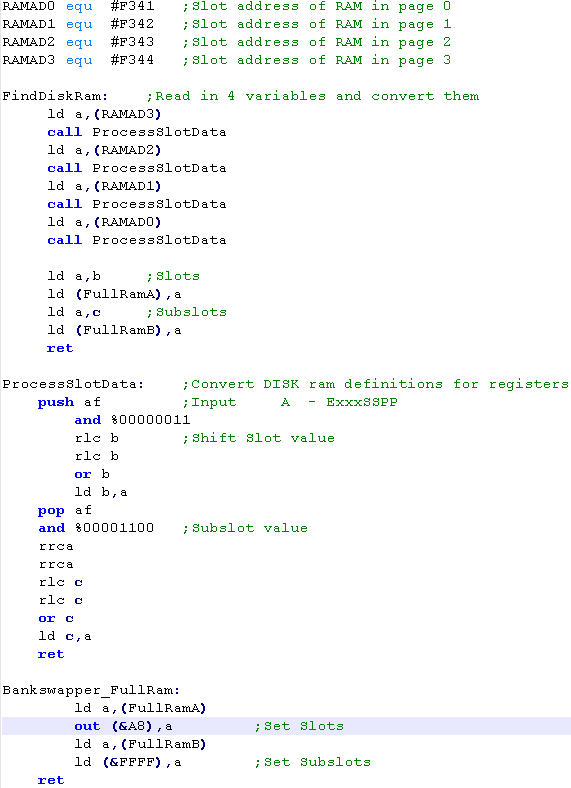 |
| The Code
above is the way ChibiAkumas finds the memory on the MSX...
as ChibiAkumas requires, and only needs 64k, and only comes
on disk, this was an easy way to solve the problem of
finding memory... Of course, if you want to release a 64k+ cartridge game on the MSX2, you'll need an alternative, and we'll look at that now! |
|
Finding Memory on Non-Disk Systems
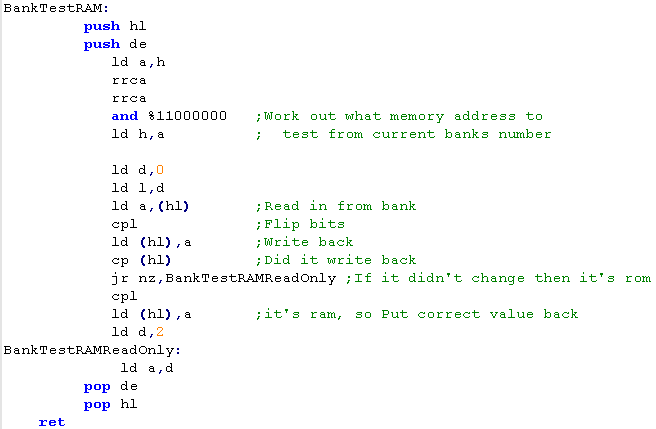
| To find the ram on a non disk
system, we have to step through each slot and subslot and see
if we can find a bank which is RAM we do this by simply writing to the bank, and seeing if the data changed - if it did, then that's our ram bank, otherwise we move on to another bank. |
 |
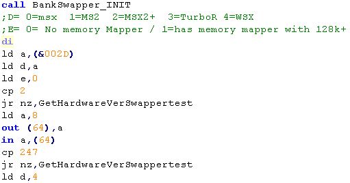
Detecting MSX version
| We can recognize the basic MSX
types simply by checking the value at memory address &002D
0 will mean an MSX1, 1=MSX2, 2=MSX2+ and 3=Turbo R if we want to detect a WSX we can out '8' to port 64 / &40 when we read back, we should get the compliment of 8 if it's a WSX type... we need to know this as the WSX has a 6mhz option on it's CPU! |
 |
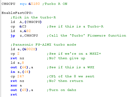
The need for SPEED!
| The Turbo-R has a 7mhz
Z80 clone that runs up to 8x the regular speed of an MSX!
We can turn it on using the 'CHGCPU' firmware function at memory address &0180... we should do this when our game starts... also the WSX has a special 6mhz Z80 that will make our game faster - we need to check if the machine is a WSX first, then out 0 to port 65 if it is... this will enable 7mhz mode! Both these functions were used in ChibiAkumas! |
 |
|
The Turbo-R is 2-8 times faster than the Z80... but there are some oddities.. firstly it will turn off during disk loading - the z80 will do all the work (it'll also turn on automatically)... also the Turbo-R has a built in limitation to the OUT command (presumably to stop the R800 locking up other hardware with its speediness!)... it will actually perform OUT commands SLOWER than the Z80 |
| The
WSX has a 6mhz Z80... like the Turbo-R it has a limitation
on it's OUT command speed... More problematic is the AY sound chip... the frequencies are all different, so your sounds will come out a different pitch! ChibiAkumas used an alternate pitch table for ArkosTracker on the WSX to compensate! |
|
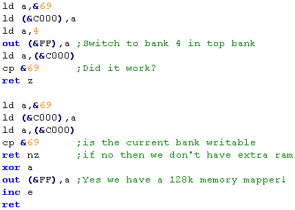
Finding a BankSwapper
| We can detect a BankSwapper by
trying to page in an extra bank of memory, and seeing if a
writable bank was actually paged in... if it was, then we must
have extra memory... if not, or we end up with ROM, or empty
space that doesn't store anything then we mustn't have any
extra memory. Unfortunately, so few MSXes have BankSwappers or more than 64k of memory it's probably pretty pointless, unless you're making your minimum requirements the Turbo-R or the MegaFlashRom |
 |
Memory Banks on the 128k ZX Spectrum
| On the ZX Spectrum 128k, the memory banks are split into 4 16k
chunks... The bottom of these (&0000-&3FFF) is always ROM This means we have 5 extra banks of memory we can page in... but there's a problem! The top one (&C000-&FFFF) is the ONLY one we can page the extra memory into, and even worse, this is the ONLY position we can use as the second screen buffer |
* +3 disk rom uses &DB00-&E7FF - must be backed up or disk system will break! |
||||||||||||||||||||||||||||||||||||||||
| The later spectrum have a more advanced mode, where we can get
rid of the ROM and have memory in all banks!! unfortunately... this is only available on the +3 and the BLACK +2 ... (not the grey +2... it's effectively a Spectrum 128)... as that means 85% of spectrums cannot use it, we can't really take advantage of it! IF we COULD... then we would have access to 4 different bank setups These were added to the spectrum to allow CPM to work - it required RAM at bank &0000 - meaning the original spectrum could not do it. |
|
Contention
| Not all banks are equal on the ZX
Spectrum! Some of the banks are 'Contended' with the screen memory.. this means that they will be slower than the other banks... to makes things worse, the contended banks are different on the +3 (and Black +2) to the spectrum 128 (and the grey+2) Banks 0 and 2 are NEVER contended on any machine... so you should use these for your main code... and the other 'possibly contended' banks for sprite data and less used code. If you were going to be super-clever, you could make your code detect the spectrum type, and use banks 1+3 for slow data on the spectrum 128, and 4+6 on the Spectrum+3 |
Dark=Contended |
Rom and Ram banking
Rom and Ram banking are handled by two ports, &1FFD and &7FFD... because these ports do other things, we need to back up the other bits when we change them... for this purpose the system keeps a backup of the current state of these ports in memory
| Bits | ||||||||||
| Port | 7 | 6 | 5 | 4 | 3 | 2 | 1 | 0 | Bit meanings | Backup |
| &7FFD | - | - | I | R | S | M | M | M | M= ram bits S=Screen page bit R=Rom Low bit I=I/O Disabling | &5B5C |
| &1FFD | - | - | - | S | D | R | - | P | P = paging mode 0=normal R=Rom high bit D = Disk Motor S=Printer strobe | &5B67 |
To select a bank of RAM at &C000, all we do is set bits 0-2 of &7FFD to a value 0-7... this will page the respective bank in at &C000
Rom Banking is possible by setting bit 2 of &1FFD and 4 of &7FFD... these bits make a number 0-4 which is the rom bank at &0000
| The
"Screen Page Bit' (bit 3 of &7FFD) allows us to to use
an alternate screen buffer in Ram Bank 7 at &C000... However, there's a problem... this can't be done on 58k machines... if you want to have a second screen buffer on 48k, you'll have to copy the screen from your buffer to &4000 with an LDIR, or some other copy command- there is NO BETTER way on a 48k! |
|
+3 Banking
This is only possible on a black +2 or +3 spectrum...setting bit 0 of &1FFD to 1 turns on this mode, and the other bits purpose changes accordingly
| Bits | ||||||||||
| Port | 7 | 6 | 5 | 4 | 3 | 2 | 1 | 0 | Bit meanings | Backup |
| &1FFD | - | - | - | S | D | O | O | P | P = paging mode 1=+3 model O=Bank Option D = Disk Motor S=Printer strobe | &5B67 |
There are 4 possible bank combinations, shown in the chart below:
| Bank | Option
0 |
|
Option
1 |
|
Option
2 |
|
Option
3 |
| &C000 | Ram 3 | Screen 2 (7) | Ram 3 | Ram 3 | |||
| &8000 | Ram 2 | Ram 6 | Ram 6 | Ram 6 | |||
| &4000 | Ram 1 | Screen 1 (5) | Screen 1 (5) | Screen 2 (7) | |||
| &0000 | Ram 0 | Ram 4 | Ram 4 | Ram 4 |
Putting it to use!
Lets learn how to bankswitch, and test the systems to see if we're on a 48k, 128k or +3 (or black +2)...
Lets learn how to bankswitch, and test the systems to see if we're on a 48k, 128k or +3 (or black +2)...
|
Note, the
Easiest way to detect different spectrums would to be look
at the ROM, read in a known location, and see if it's bytes
match what we expect... However some machines use non-standard ROM, so this is not advised - but it may be enough if you're not too worried about compatibility! |
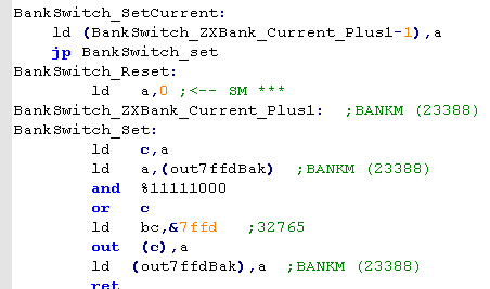
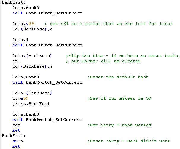
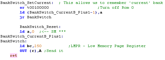
| We're going to create a command
called Bankswitch_SetCurrent.. this will set a permanent
bankswitch... We can also use Bankswitch_Set... this will temporarily set a bank... and Bankswitch_Reset will undo it! These were taken from the ChibiAkumas game! |
 |
| We're going to test to
see if we have 128k banks! We do this by writing a marker, changing to an alternative bank... then altering the address we wrote the marker to... When we swap back to the original bank, we should see the marker, if we do not, then the bankswitch did not work, and we must only have 48k |
 |
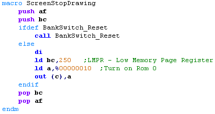
| We're going to do pretty much
the same thing with the +3... however there are some problems! The backups of the &7FFD and &1FFD registers, and the stack are in the &5000 range... we're going to have to use 'Option 0'... as our program code is in Ram Bank 2 we need that not to move, but we will need to back up &5B5C and &5B67 into D and E before we try to turn on the +3 bank... we'll also need to avoid using the stack. Again, we write our marker Then we apply the +3 switch... flip the bits at the address of the marker data, and turn it off! if the marker is still there, we have a +3... if not, we have a 128k machine. |
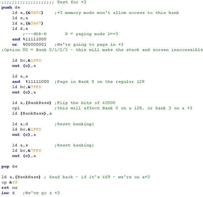 |
| Don't try
to detect a +3 until you've detected 128k... it won't work! Also note we're paging in bank 0 AFTER turning on +3 mode... turning +3 on caused a bank swap on the 128k for some reason! |
|
|
Note, this detection
code was written for these tutorials... ChibiAkumas required
128k, and did not work differently on +3 (except the disk
routines.. and these were a different build of the game) Use the code above at your own risk! it seems to work, but hasn't had much testing! |

| The Enterprise and it's OS supports up to 256x 16k banks for
an insane 4MB of memory (though some may be rom!) The most basic system supports 64k, but there is also a 128k version (the EP128)... There are two special segments... the Zero Segment containing the RST's, and our program, (loaded at &0000) and the system segment (loaded at &8000 by default)... around 2/3rds of the system bank will be used by the OS... the rest will be free. it's important to notice, ONLY memory banks in the base 64k can be used for video memory. We can use the Zero page bank if we want... but we must 'request' ALL other banks from the OS before using them... it will find one, and tell us what it's allocated - if all the banks are used, it will give us the spare memory of the system page, The diagram to the right, shows how the OS allocates memory on these two systems. Essentially the internal memory has bank numbers 255-252 (FF-FC)... as we add more memory, we will get lower and lower numbered banks... for example a 256k system will have banks down to 240 (F0) The top bank (255) is used as the system segment... the bottom bank (number will depend on upgrades) will be the Zero page... The system will allocate banks in consecutive order... so we won't use the internal 64k until we have no choice... this means we can be sure to have it available for Vram! Low numbers (for example banks 0-4) will be rom. |
64k
Bank
(Can be Vram)
Extended bank (Cannot be vram) |
Asking for memory... and giving it
back to the OS!
| We can ask the OS for memory, and then use it for whatever we
want... if we don't need it any more, we can tell the OS to take
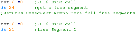
it back! This is how we get a free VRAM bank... we ask for memory banks, until we get one >=FC (a 64k internal bank)... This may take a while, as the OS gives us the low numbered banks first... but once we get one, we can just free up all the ones we didn't really want! We use RST 6 to do an EXOS call... and command 24 to request a segment, and 25 to give it back! |
 |
Lets look at the details of these two commands:
EXOS Function 24 - Allocate Segment
This command will request another 16k segment... status reg will be Zero if succeeded, NZ if another full 16k is not available
If succeeded the segment number will be returned in C... if only a shared segment was available, the boundary will be in DE
Parameters: none
Returns: A=status C=segment number DE=EXOS boundary within this segment (if returned is a shared segment, otherwise &4000)
EXOS Function 25 - Free Segment
This command will free a 16K segment of RAM. The segment must have been allocated via EXOS function 24.
Parameters:
C=segment
number
Returns: A=status
Returns: A=status
| If we
don't need the OS, we can just use the memory ourselves
without asking... But if we want it to do Disk reading or other things for us, we need to play nice! It all depends on how you plan to use the system, and how worried you are about compatibility. |
|
Using our Segments!
| Remember how limited our bank swapping options were on the CPC
and Speccy? Remember how we wished we had a memory mapper on all MSX2? Well, the Enterprise really delivers on this front! Just like the other systems, the memory map is split into 16k banks... But any 16k segment can be mapped into any one these banks... you can even have the same segment in two banks! So far as I've seen, the memory mapping ability of the Enterprise is second to none in the Z80 range... even the Sam Coupe is heavily limited in comparison! Each chunk of memory uses a different port... and we just OUT the segment number to that port to change the active segment in that memory range... For example, if we want to set &C000-&FFFF to segment &F3 we just do... ld a,&F3 out (&B3),a it couldn't be easier! |
|
|
ChibiAkumas for the
enterprise 'faked' the CPC bank swapping, only paging the extra
ram into &4000... The Enterprise's Screen and Ram compatibility with the CPC made Porting ChibiAkumas to the EP128 easy! Even the sprites were the same!... It would have been harder if the game used Mode 0, however, because the last 8 colors are more limited in Enterprise 16 color mode. |
Detecting our system...64k, 128k or 256k
| In our tutorials, we've already
taken 1 segment for the &8000 range, one for the VRAM, and
the system will use two for the Zero and System segments... That means we should be able to request 4 full banks on a 128k machine, or 12 on a 256k machine... on a 64k machine we'll be able to get no full banks (just the partial segment) We'll keep requesting banks until the OS says NO, and we'll know how much ram the system has. If we want we can then keep all the banks we requested, or we can free them back to the operating system. |
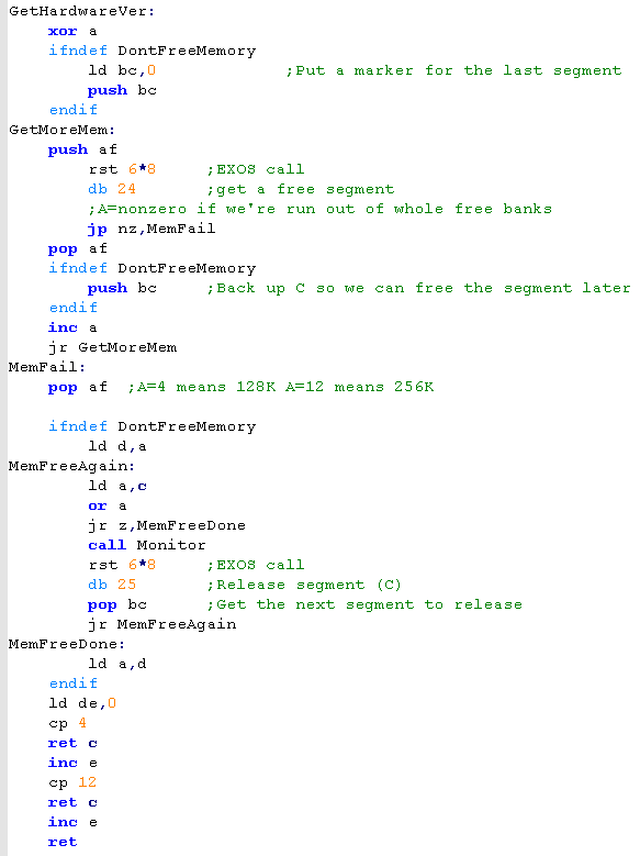 |
| Setting
the
'DontFreeMemory' symbol will stop this example giving the
memory back to the OS, but it doesn't store it anywhere...
you'd probably want to add an extra command to do that!... if
we don't we'll have to 'guess' what banks were free! In theory, on a 128k machine, banks &F9-&FE will be free for our use (and &FC will have been allocated to our screen)... but who knows, maybe the user has some weird upgrade ROM that's using one... you've just got to ask yourself... 'do I feel lucky?' |
|

Bankswitching theory on the Sam
Coupe
Controling bank switching on the SAM is
done with two ports, one controls the first 32k of the memory map, the
other controls the second 32k, there's also a port that controls the
bank pair that controls the visible screen (the screen uses 24k so two
banks)
The SAM splits its 256/512k into 16k chunks, with the first bank is 0...
The SAM splits its 256/512k into 16k chunks, with the first bank is 0...
| Port | Name | Description | Bits | Bit Meaning |
| &FA - 250 | LMPR | Low Memory Page Register | WHLBBBBB | B=Bank &0000-&7FFF... L=Low rom off (1=off)... H=High rom on (1=on)� W=Write protect &0000-&3FFF |
| &FB - 251 | HMPR | High Memory Page Register | MCCBBBBB | B=Bank &8000-&FFFF... C=mode 3 color lookup... M=use external memory expansion |
| &FC - 252 | VMPR | Video Memory Page Register | OMMBBBBB | B=Video Bank... M=Mode... O=midi Io |
You'll notice we only have two bank
switching ports... this is because we switch the memory range in 32k
chunks!
even though memory banks are split in 16k.... if we set port 250 to use bank 0... then the memory range &0000-&3FFF will point to bank 0... but the next bank (&4000-&7FFF) will use the following bank - bank 1!... The fact we have to work in 32k chunks makes bank switching on the SAM rather limited compared to other systems where we work in 16k chunks
Also notice bit 7 of port 251... this allows us to access external memory upgrades in the range &8000-&FFFF for many megabytes of memory - we won't be cover them in these tutorials!
| Range |
Page Addr | Example |
| &0000 | (&250) | 0 |
| &4000 | (&250)+1 | 1 |
| &8000 | (&251) | 10 |
| &C000 | (&251)+1 | 11 |
|
Because we need to swap
banks in 32k chunks it makes it harder to uses memory
efficiently on the SAM... if we page in the screen into one
bank, and our sprites into the other... we have nowhere left for
our code! We will have to work out another way to organize our memory... for example storing a copy of our sprite handling code in the spare memory of the screen bank (the screen uses 24k of the 32k bank) |
Making use of Sam Coupe bank
swapping
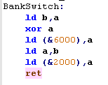
| We're going to define some
commands for setting the lower ram bank
(&0000-&7FFF)... this is because our code is in the
other bank at &8000! We'll use SetCurrent to set the bank - and we'll create Reset command to restore the bank we set with SetCurrent... we need this for a good reason! |
 |
| Our program code is in the
&8000 range... and because we need to page in the 24k
screen... we have to do this at the &0000-&7FFF
range... but we're also going to use this for our extra ram. We're going to have to modify our bitmap code, to use the reset command to restore whatever bank we asked for with SetCurrent rather than turn the ROM back on. |
 |
| To test if we've got 512k of
memory, we'll use the same procedure as before... bank 31 is
the top bank in the 512k range - we'll try to page it in and
write to it... If the write occurs in our current bank, then we don't have 512k. |
 |
  |
Bank Switching and hardware detection on the Gameboy and GBC |
One way to detect the GBC is to check
the A register on startup...On a GBC, A=&11... however we'll
actually detect the GBC using RAM bankswitching to do a really
thorough job!... We'll also learn how to page in the GBC extra ram
bank, and how to turn on 8mhz "Turbo" mode on the GBC!
We're going to need a few hardware registers for today's lesson!
We're going to need a few hardware registers for today's lesson!
| Section | Addr | Name | Bits | Bit Meaning |
| Joy | FF00 | P1/JOYP - Joypad (R/W) | --BD3210 | B=Buttons D=Direction 3210=buttons DULR SSBA |
| CPU | FF4D | KEY1 - CGB Mode Only - Prepare Speed Switch | C------P | C=Current speed P=prepare switch |
| RAM | FF70 | SVBK - CGB Mode Only - WRAM Bank (bits 0-2 =0-7) | ||
| INT | FFFF | IE - Interrupt Enable (R/W) | ---JSTLV | J=Joypad S=Serial T=Timer L=Lcd stat V=vblank |
RAM and ROM
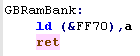
| Banking in the extra GBC ram is super easy! we just write a number from 1-7 to memory address &FF70... the bank will be paged in to memory address &D000-DFFF Note if you try to page in "Bank 0" you will get "Bank 1"... there is no bank 0! |
 |
| ROM banking is also easy, we just need to write a value to
&2000, this will page a rom bank number into area
&4000-&7FFF Note, we also write a 0 to address &6000 - this is to tell the hardware our banker is an ALL ROM banker - and has no RAM |
 |
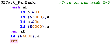
| Gameboy cartridges can also have 32k of extra RAM! This will
appear in the area &A000-&BFFF as 4x 8k pageable banks!
Just like the ROM, it's very easy to use... first we write 1 to address &6000 to tell the system we have RAM Then we enable the RAM bank by writing &0A to &0000 - we turn it off by writing &0 to &0000 Finally, we can select the bank number (0-3) by writing to &4000 The Rambank will be available between &A000-&BFFF |
 |
| Make sure
you turn of cartridge RAM when you're not using it... if the
player is mean, they may turn off the gameboy at a strange
time... and the battery backed up ram could get corrupted
>:( |
|
Turbo mode!
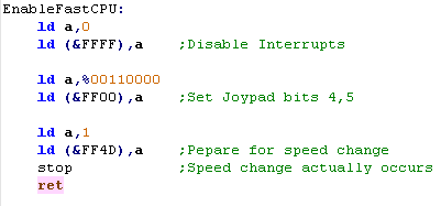
| Turning on 8mhz mode of the
Gameboy Color is also pretty easy... First we have to disable interrupts by writing 0 to &FFFF, then we have to set bits 4,5 of the Joystick line (not sure why... but we do!) at address &FF00 Then we make a 'Prepare speed change' request to port &FF4D Finally we need to STOP the processor... when it restarts we will be in 8mhz mode! |
 |
|
Trying to
turn the fast cpu on on a Gameboy seems to have no effect....
but probably isn't a good idea... so detect the hardware
first, and don't do it on a regular GB! |
|
Bank Switching on the Sega Mastersystem and GameGear |
| We're not going to try to detect
if we're running on the SMS or Gamegear - as there is no real
purpose... we're building for the two systems separately, so any
hardware differentiation should be done with conditional
compilation (IFDEF statements) We can, however use extra cartridge ROM, and up to 32k of extra RAM contained in the cartridge! |
|
||||||||||
| Writing a value to addresses &FFFD-FFFF of 0 or above will page that ROM bank into the appropriate address range. |  |
||||||||||
| Address &FFFC controls the extra 'in cartridge' ram bank... it has two banks of 16k ram... these can be paged in to the &8000-&BFFF range | 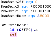 |
| It's
SUPPOSED to be possible to bank the cartridge RAM into the
shadow RAM are of the addressible range, by writing
%00011100... however it doesn't seem to work! It seems it may not actually be supported by the emulator, as if appears no commercial games actually use it. |
|
|
Lesson
P30 - Hardware Sprites on the gameboy The Gameboy has 'Hardware sprites'... these are drawn by the graphics hardware, so are very fast, but are limited in size, and number. |
 |
 |
 |
The Theory of Sprites
Gameboy sprites are 8x8, or 8x16 and we
can have up to 40...
8x16 mode can be turned on by setting Bit 2 of FF40... we also need to set Bit 1 of FF40 to turn sprites on at all!
8x16 mode can be turned on by setting Bit 2 of FF40... we also need to set Bit 1 of FF40 to turn sprites on at all!
| Bit | |||||||||
| Address | 7 | 6 | 5 | 4 | 3 | 2 | 1 | 0 | Meaning |
| FF40 | L | w | W | T | M | s | S | B | B= Background Display (CGB only) S=Sprite Enable s= sprite size (8x16) M=tileMap address (0=9800-9BFF 1=9C000-9FFF) |
| T=Tile Data (0=8800-97FF 1=8000-8FFF) W= Window Enable w=window tilemap (0=9800-9BFFF 1=9C000-9FFF) L= Lcd enable | |||||||||
| Sprite Data is stored from &FE00 onwards, it can ONLY be
accessed during Vblank there are 40 sprites, and each definition uses 4 consecutive bytes... For Example, Sprite 0's bytes are highlighted in black... it has a Y co-ordinate, an X co-ordinate, a Tile Number, and tile Attributes Y and X are offset, so you can have a sprite partially off the screen, You need to set XY to (8,16) to get the top corner of the screen (0,0) the 'Sprite number' refers to a pattern within the tile definitions in memory area &8000-&8FFF - Sprites bitmap data is in the same format as the tilemap... In 8x16 mode is enabled, then the tiles are used in pairs - the bottom bit is unused, and odd numbered tiles are ignored Attributes:
Bits 7-4 work on both GB and GBC On the Gameboy, we can only use palette 1 or 0.... on the color gameboy we can use palette 0-7 Note: Color 0 is always transparent on sprites Tile-Sprite prority allows us to put Sprites BEHIND the background... |
|||||||||||||||||
| You can't
write to Sprite ram outside VBLANK - which is a total pain! Fortrunately the Gameboy has a DMA (Direct Memory Access)... this is where the hardware automatically copies an area of normal ram into Sprite ram - it's automatic and super-fast... so it can copy a 'cache' of the sprite data to the real sprite ram in vblank! |
|
Using DMA for
Vblank!
| Because we can only change
sprites during Vblank, we need to set up a DMA interrupt to do
the job for us. We can turn on VBLANK by setting Bit 0 of &FFFF and Enabling interrupts with EI.... when Vblank occurs, a call will be made to memory address &0040 (64) The gameboy DMA is desinged to copy sprites, we just write the High byte of the source address to &FF46 - the transfer will occur ... we need to wait a bit for it to finish... HOWEVER.. during the DMA only the memory &FF80-&FFFE is accessible... So we need to copy some code to &FF80 to run the dma, and Jump to &FF80 at address &0040 Finally we need to turn on the Vblank interrupt , and Enable Interrupts |
Address of Cache and Vblank
handler in High Ram (&FF80-FFFE) Copy the interrupt handler to &FF80 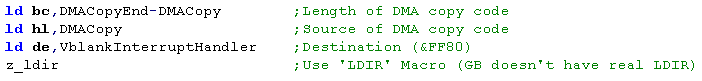 Jump to interrupt handler at &0040  Enabling Vblank and interrupts: 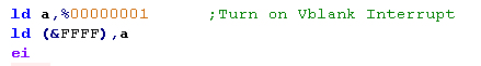 The DMA execution routine we copy to &FF80 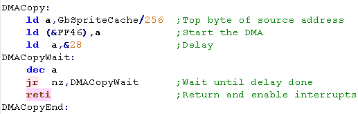 |
|
You can try to use a 'Wait command' before writing to the sprite memory instead of using DMA - but since you can't write to Vram out of Vblank it will be difficult |
Setting the
Sprite!
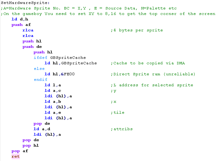
| Now we have the Cache for the
Sprite data, we can actually set up the sprites, we'll use a
little routine to do this for us! We'll pass the X,Y co-ordinates in BC ... the tile number of the pattern data for the sprite in E, and the attributes of the tile (color etc) in H... and the tile number in A Because each sprite has 4 bytes - we need to multiply A by 4 - and add it to the starting address of the sprite data... then we set the other 4 bytes for the various attributes |
 |
| We use this function to position 4 sprites onscreen, 8 pixels apart! | 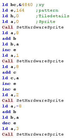 |
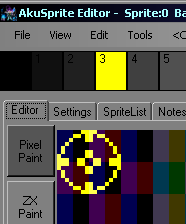
| We've used 2x2 sprites (4 in
total) to make a 'crosshair' 16x16 pixels. Note: you can use AkuSprite Editor to create GB tiles - which are the same format as the sprite data. |
 |
Continue to Page 4
Back to Page 2
| View Options |
| Default Dark |
| Simple (Hide this menu) |
| Print Mode (white background) |
| Top Menu |
| ***Main Menu*** |
| Youtube channel |
| Patreon |
| Introduction to Assembly (Basics for absolute beginners) |
| Amazon Affiliate Link |
| Forum |
| AkuSprite Editor |
| ChibiTracker |
| Dec/Bin/Hex/Oct/Ascii Table |
| Alt Tech |
| Archive.org |
| Bitchute |
| Odysee |
| Rumble |
| DailyMotion |
| Please note: I wlll upload more content to these alt platforms based on the views they bring in |
| 68000 Content |
| ***68000 Tutorial List*** |
Learn 68000 Assembly  |
| Hello World Series |
| Platform Specific Series |
| Simple Samples |
| Grime 68000 |
| 68000 Downloads |
| 68000 Cheatsheet |
| Sources.7z |
| DevTools kit |
| 68000 Platforms |
| Amiga 500 |
| Atari ST |
| Neo Geo |
| Sega Genesis / Mega Drive |
| Sinclair QL |
| X68000 (Sharp x68k) |
| 8086 Content |
| Learn 8086 Assembly |
| Platform Specific Series |
| Hello World Series |
| Simple Samples |
| 8086 Downloads |
| 8086 Cheatsheet |
| Sources.7z |
| DevTools kit |
| 8086 Platforms |
| Wonderswan |
| MsDos |
| ARM Content |
| Learn ARM Assembly |
| Learn ARM Thumb Assembly |
| Platform Specific Series |
| Hello World |
| Simple Samples |
| ARM Downloads |
| ARM Cheatsheet |
| Sources.7z |
| DevTools kit |
| ARM Platforms |
| Gameboy Advance |
| Nintendo DS |
| Risc Os |
| Risc-V Content |
| Learn Risc-V Assembly |
| Risc-V Downloads |
| Risc-V Cheatsheet |
| Sources.7z |
| DevTools kit |
| MIPS Content |
| Learn Risc-V Assembly |
| Platform Specific Series |
| Hello World |
| Simple Samples |
| MIPS Downloads |
| MIPS Cheatsheet |
| Sources.7z |
| DevTools kit |
| MIPS Platforms |
| Playstation |
| N64 |
| PDP-11 Content |
| Learn PDP-11 Assembly |
| Platform Specific Series |
| Simple Samples |
| PDP-11 Downloads |
| PDP-11 Cheatsheet |
| Sources.7z |
| DevTools kit |
| PDP-11 Platforms |
| PDP-11 |
| UKNC |
| TMS9900 Content |
| Learn TMS9900 Assembly |
| Platform Specific Series |
| Hello World |
| TMS9900 Downloads |
| TMS9900 Cheatsheet |
| Sources.7z |
| DevTools kit |
| TMS9900 Platforms |
| Ti 99 |
| 6809 Content |
| Learn 6809 Assembly |
| Learn 6309 Assembly |
| Platform Specific Series |
| Hello World Series |
| Simple Samples |
| 6809 Downloads |
| 6809/6309 Cheatsheet |
| Sources.7z |
| DevTools kit |
| 6809 Platforms |
| Dragon 32/Tandy Coco |
| Fujitsu FM7 |
| TRS-80 Coco 3 |
| Vectrex |
| 65816 Content |
| Learn 65816 Assembly |
| Hello World |
| Simple Samples |
| 65816 Downloads |
| 65816 Cheatsheet |
| Sources.7z |
| DevTools kit |
| 65816 Platforms |
| SNES |
| eZ80 Content |
| Learn eZ80 Assembly |
| Platform Specific Series |
| eZ80 Downloads |
| eZ80 Cheatsheet |
| Sources.7z |
| DevTools kit |
| eZ80 Platforms |
| Ti84 PCE |
| IBM370 Content |
| Learn IBM370 Assembly |
| Simple Samples |
| IBM370 Downloads |
| IBM370 Cheatsheet |
| Sources.7z |
| DevTools kit |
| Super-H Content |
| Learn SH2 Assembly |
| Hello World Series |
| Simple Samples |
| SH2 Downloads |
| SH2 Cheatsheet |
| Sources.7z |
| DevTools kit |
| SH2 Platforms |
| 32x |
| Saturn |
| PowerPC Content |
| Learn PowerPC Assembly |
| Hello World Series |
| Simple Samples |
| PowerPC Downloads |
| PowerPC Cheatsheet |
| Sources.7z |
| DevTools kit |
| PowerPC Platforms |
| Gamecube |
| Work in Progress |
| ChibiAndroids |
| Misc bits |
| Ruby programming |
Buy my Assembly programming book
on Amazon in Print or Kindle!


Available worldwide!
Search 'ChibiAkumas' on
your local Amazon website!
Click here for more info!


Buy my Assembly programming book
on Amazon in Print or Kindle!
Available worldwide!
Search 'ChibiAkumas' on
your local Amazon website!
Click here for more info!
Buy my Assembly programming book
on Amazon in Print or Kindle!
Available worldwide!
Search 'ChibiAkumas' on
your local Amazon website!
Click here for more info!