

 |
Don't like to read? you can learn while you
watch and listen instead! Every Lesson in this series has a matching YOUTUBE video... with commentary and practical examples Visit the authors Youtube channel, or Click the icons to the right when you see them to watch the Lessons video! |
 |

Table of Contents
Introduction
The Z80
Numbers in assembly
Beginners Series - lets learn the basic Z80 commands by example!
Hello World Series - Super simple Hello world examples
Platform Specific Series - Lets learn how the hardware of the systems work, so we can get it to do what we want... Covers Amsrad CPC,MSX,ZX Spectrum, TI-83,Enterprise 128/64 and Sam Coupe!
| Lesson
A1
- Binary Coded Decimal |
|
| Lesson A2 - Interrupt Mode 2 |
Multiplatform Series - Using code provided that will talk to the hardware, lets write programs that works instantly on multiple systems!
Appendix
Other series - No need to just limit yourself to the Z80... still want more, check out these series!
| Learn Multi platform 6502 Assembly Programming... For Monsters! | |
| Learn Multi platform
68000 Assembly Programming... By Magic! |
Platforms covered in these tutorials
Amstrad CPC
Elan Enterprise
Gameboy and Gameboy Color
Master System & GameGear
MSX & MSX2
Sam Coupe
TI-83
ZX Spectrum
Camputers Lynx
Z80 Links
Zilog Z80 manual - The official manual , it's compelx, but if you need a definitive answer you'll find it here so this should be in your toolkit
Z80 Documented - Details of undocumented opcodes
Learn ASM in 28 days - I learned from this tutorial, it's aimed at the TI-83 calc, but that uses a Z80... if you don't like my tutorial, try this one!
Down to the silicon - Not remotely needed for programming, but this amazing technical breakdown of how the Z80 works is really something
Vasm - The recommended assembler is WinApe, however if you don't want to use windows, the Open source VASM in 'OldStyle' mode will work too.
 |
If
you
want to learn Z80 get the Cheatsheet!
it has all the Z80 commands, and useful info on the CPC,
Spectrum and MSX! It will give you a quick reference when you're stuck or confused - and it's what the author used to develop ChibiAkumas! Print it in color at high resolution on 2 sides of A4 for maximum performance! If you're interested in the 24 bit eZ80 - there's a special eZ80 CheetSheet here |
 |
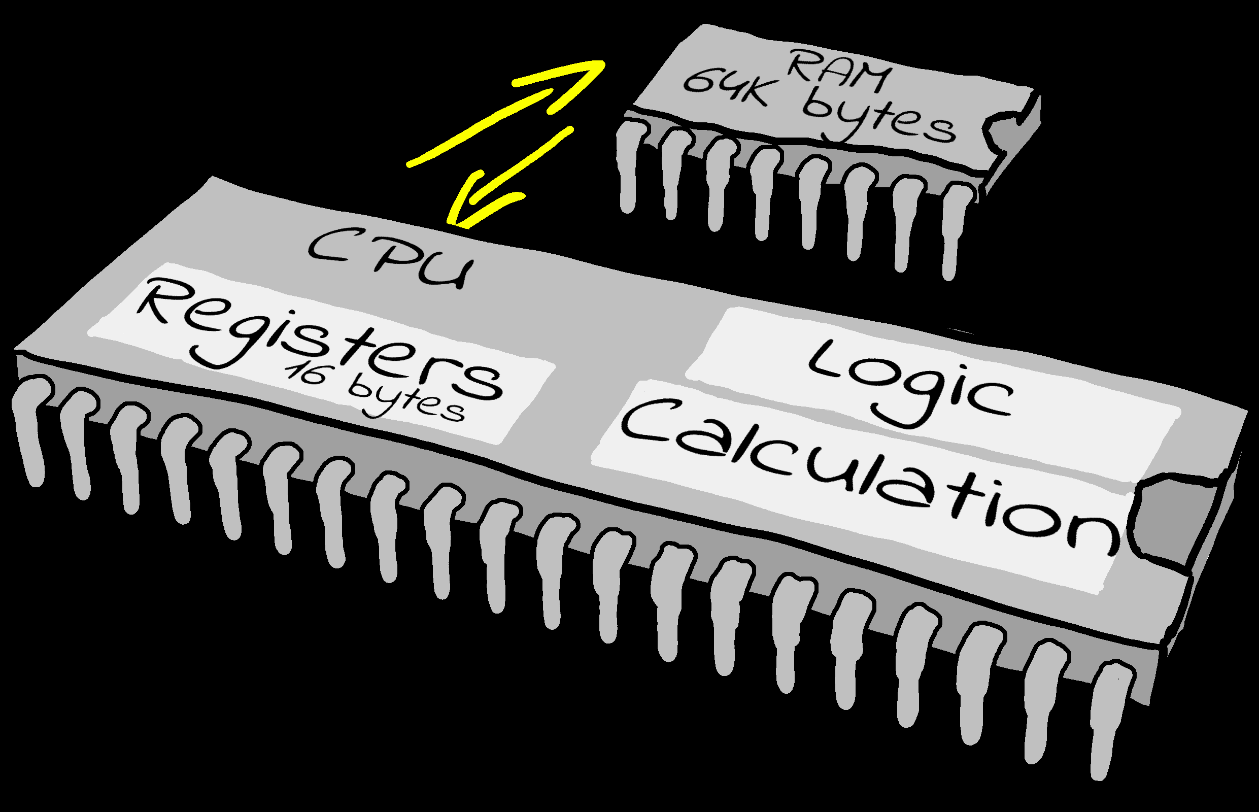
Introducing the Z80.
The Z80 is an 8 bit processor, usually around 4 MHz, but 6mhz versions
exist.
The MSX Turbo-R R800 is also 100% Z80 compatible, with 4x the effective
speed.
Each Register can only store one byte (0-255), but some registers can be used in certain cases together as 16 bit pairs. For example HL together are 16 bits, and can store 0-65535.
Each of the registers has a 'purpose' it is intended for, but you can
use any register for anything you want!
The different registers all have 'strengths' because many commands will
only work with certain ones, and some commands may be slower or need
more code if you use the wrong one.
The Z80's large number of registers makes Z80 programming very different to a system like the 6502.
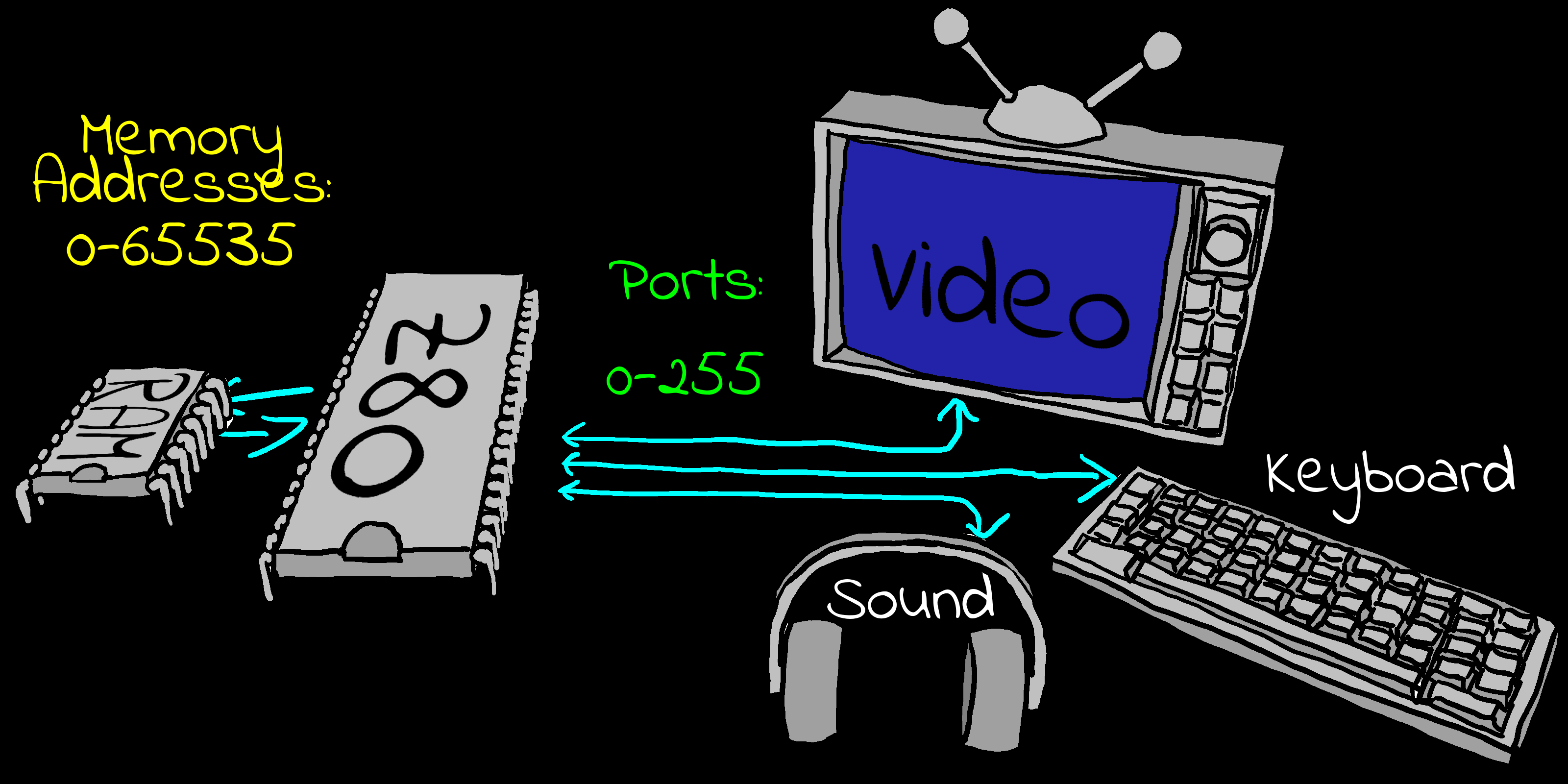
The Z80 uses a 16 bit address bus. This means it can address $0000-$FFFF (0-65535), giving a total of 64K. Systems like the 128K Amstrad 6128 get around this limitation via bank switching.
In addition to the addressable memory, the Z80 also addresses hardware ports via OUT and IN.
On some systems, like the MSX, ports are 8 bit. These use register C as the port number in commands like "OUT (C),A" but on other systems, like the CPC or Spectrum, ports are 16 bit using BC as the port number. Annoyingly the command is still the rather misleading "OUT (C),A".
You may wonder why some use 8 bit ports, and some use 16 bit ones. The difference is not the Z80 itself, but how the Z80 is wired up in the computer.
On the Z80, when commands have two parameters, the parameter on the right is the source, the parameter on the left is the destination.
For Example: "ADD HL,DE" will add the source DE to the destination HL.
Finally it should be noted the eZ80 is a more enhanced Z80 with a 24 bit address bus, which is also backwards compatible with the Z80.
The Z80 Registers
|
A |
The
Accumulator is used
during all our main calculations. |
|
F |
The Flags
Register. Each bit defines a 'condition' we can test for. |
|
HL |
The High Low
pair. |
|
BC |
These are
often used as a Byte Count or loop counter. |
|
DE |
DE is often
used as a Destination. |
|
IX |
Sometimes we
want to get to memory by specifying a relative position.
Index Registers allow us to do this. |
|
IY |
IY works the
same as IX. |
|
PC |
This is the
place in memory that the Z80 is running. |
|
SP |
This is the
stack pointer. |
|
R |
This is the
Refresh register. |
|
I |
This is the
Interrupt vector register, it's only used by Interrupt Mode 2
(IM 2). |
The Z80 Shadow Registers
The Shadow registers are 'extra' registers that are swapped with the main ones.
These are AF' (Accumulator and Flags) BC' DE' and HL'. There is no shadow IX/IY or SP.
These shadow registers are usually used during the interrupt handler, so the main registers are unchanged for when the interrupt handler ends. You probably won't be able to use them unless interrupts are permanently disabled, or you write your own interrupt handler.
There are two exchange commands: "EX AF,AF'" swaps the Accumulator+Flags, "EXX" swaps BC,DE and HL.
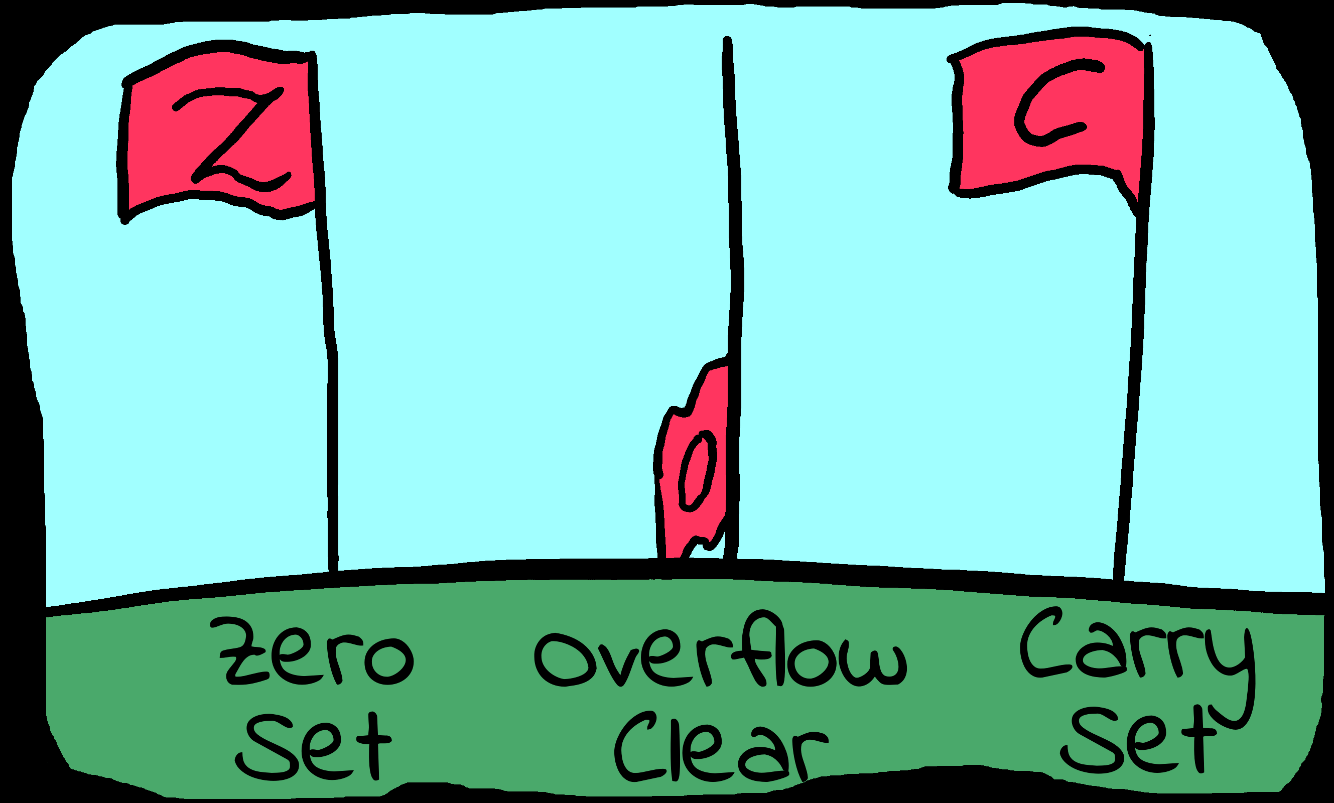
The Z80 Flags
The flag register contains 8 one bit 'states'. Each keeps track of an attribute of the last command we performed.
For Example: If we do a compare like "CMP #0", the Z flag will be set if the accumulator is zero. The S flag will be set if the accumulator is negative. We can use these later with conditions to branch to different parts of our code.
The Z80 'F' Register contains 8 bits: %SZ-H-PNC .
The main ones you will need to know about are Carry (C) and Zero (Z). Sign (S) is also useful in some cases, but you'll probably never actually need to know about P/V, H and N.
On the Z80 many commands do not change the flags. You need to check if the command you're using actually updates them.
For Example: "DEC B" will correctly update the zero flag, "DEC BC" will not, so with "DEC BC" you'll need to manually check if B and C are zero. This can be done with "LD A,B OR C".
|
Bit |
Flag |
Name |
Description |
|---|---|---|---|
|
7 |
S |
Sign |
Positive / Negative |
|
6 |
Z |
Zero |
Zero Flag (0=zero) |
|
5 |
- |
|
|
|
4 |
H |
Half Carry |
Used by DAA |
|
3 |
- |
|
|
|
2 |
P / V |
Parity / Overflow |
Used for Overflow - if a sign changes because
a register is too small |
|
1 |
N |
Add / Subtract |
Used by DAA |
|
0 |
C |
Carry |
Carry / Borrow |
In the instruction references of my book, the 'Flags Affected' section
will show a minus '-' when an instruction leaves a flag unchanged, an
uppercase letter when a flag is correctly updated (for example 'C'), and
a lowercase letter when a flag is changed to an undetermined state (for
example 'c').
Z80 Conditions
The Z80 has a variety of condition codes, which can be applied to Jumps, Calls and Returns:
|
Condition |
Meaning |
Flag |
|---|---|---|
|
Z |
Zero |
Z Set |
|
NZ |
Non Zero |
Z Clear |
|
C |
Carry |
C Set |
|
NC |
No Carry |
C Clear |
|
PO |
Parity Odd |
P/V Clear |
|
PE |
Parity Even |
P/V Set |
|
P |
Positive Sign |
S Clear |
|
M |
Minus Sign |
S Set |
Special Addresses on the Z80
There are some special addresses on the Z80 processor that are common to all Z80 systems.
The most important are:
RST0 ($0000 - Reset) which is usually the first command executed as the
system restarts.
RST7 ($0038 - IM1 Interrupt) which is called by interrupts (Usually
VBlank) in Interrupt Mode 1.
NMI ($0066 - Non Maskable Interrupt) is a special interrupt which can be
caused by connected hardware, and cannot be turned off with DI.
Note: These may be 'ROM' on some systems (Like the SMS/MSX and ZX
Spectrum). This will make using a custom interrupt handler in IM1
difficult or impossible.
The purpose of the NMI address ($0066) will differ depending on the
system.
For Example: On the CPC and ZX Spectrum it's not typically used, however
the Multiface II Stop button will cause an NMI interrupt (and a call to
address $0066).
On the Master System the NMI is more important. an NMI interrupt occurs when the 'Pause button' is pressed on the console unit.
|
Address |
Purpose |
Detail |
|---|---|---|
|
$0000 |
RST0 |
Reset |
|
$0008 |
RST1 |
|
|
$0010 |
RST2 |
|
|
$0018 |
RST3 |
|
|
$0020 |
RST4 |
|
|
$0028 |
RST5 |
|
|
$0030 |
RST6 |
|
|
$0038 |
RST7 |
IM1 Interrupt Handler |
|
$0066 |
NMI |
Non Maskable Interrupt |
Representing data types in source code
Here are the typical ways Z80 assemblers represent the different data types:
|
Prefix |
Alternatives |
Example |
Meaning |
|---|---|---|---|
|
|
|
12 |
Immediate Decimal Value. |
|
% |
|
%10101010 |
Immediate Binary Value |
|
& |
# $ |
&FF |
Immediate Hexadecimal Value |
|
' |
|
'A' |
Immediate ASCII Value |
|
() |
|
-1000 |
Memory Address in Decimal |
|
(&) |
(#) ($) |
(&1000) |
Memory Address in Hexadecimal |
Defining bytes of data on the Z80 in Vasm
There will be many times when we need to define bytes of data in our code. Examples of this would be bitmap data, the score of our player, a string of text, or the co-ordinates of an object.
The commands will vary depending on the CPU and your assembler, but the ones shown below are the ones used by the assembler covered in these tutorials.
For Example: If we want to define a 16bit sequence &1234 we would use "DW &1234".
|
Bytes |
Z80 |
6502 |
68000 |
8086 |
ARM |
|---|---|---|---|---|---|
|
1 |
DB |
DB |
DC.B |
DB |
.BYTE |
|
2 |
DW |
DW |
DC.W |
DW |
.WORD |
|
4 |
|
|
DC.L |
DD |
.LONG |
|
n |
DS n,x |
DS n,x |
DS n,x |
n DUP (x) |
.SPACE n,x |
Z80 Addressing Modes
| Addressing mode | Description | Example |
| Immediate Addressing | A single byte fixed number parameter is specified as a parameter after the Opcode. | ADC 128 XOR 128 |
| Immediate Extended Addressing | A pair of bytes is specified as a parameter. | LD BC,$1000 LD HL,$C000 |
| Modified Page Zero Addressing | RST calls are effectively a jump to an address starting $00##. We specify the single ## byte for the call. | RST 0 RST $38 |
| Relative Addressing | Relative addressing is where the parameter is an 8 bit signed byte offset (-128 to +127) relative to the current Program Counter position (the position AFTER the JR command) | JR 16 JR -100 |
| Extended Addressing | A 16 bit address used as a destination, either for a jump, or for
the address to load or store a parameter. The parameter will be specified in brackets (##) to show the value is not an immediate. |
JP $1000 LD A,($C000) |
| Indexed Addressing | One of the two index registers (IX or IY) plus a displacement
offset are specified. The displacement is an 8 bit byte, so has the possible range -128 to +127. |
LD A,(IX+1) XOR (IY-4) |
| Register Addressing | This is simply where the source or destination parameter is a register. | LD C,4 LD H,B |
| Implied Addressing | This is where one of the parameters is implied (usually the Accumulator). | SUB 4 CPL |
| Register Indirect Addressing | This is where a 16 bit register is specified, but the address in that register is the source of the parameter, not the value in the register itself. The register will be specified in brackets. | JP (HL) XOR (HL) |
| Bit Addressing | This is where a single bit of a register is being read or altered in a register. | BIT 6,L RES 1,C |
| Addressing Mode Combinations | Multiple combinations of addressing modes can be used as the
source and destination in some cases. |
BIT 6,(HL) LD E,(IX+1) |
Endian, Big Endian and Little Endian
| Even on an 8 bit system there will be times
when we need to store a 16 bit or more number, and whether our
CPU is 8,16 or 32 bits, each memory address in RAM will only
store 1 byte, so we'll need to split larger numbers up into
individual bytes for storage.
Let's imagine we have 32 bits to store, this will take four bytes of RAM. But in what order should these four bytes be stored? It may be surprising to hear that there are two options. 'Big Endian' stores the highest byte first and the lowest
byte last. It's not really up to us what 'Endian' to use, as our CPU
will have its 'Endian' built into its memory addressing. |
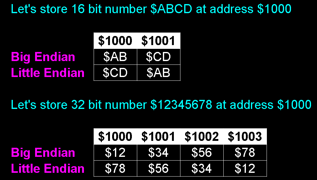 Big and Little Endian compared. |
Number representation... Hex Dec and Bin?! Bytes, Bits and Nibbles???
There are various forms of representation for numbers we'll want to know about. The representation we'll use in our code will vary depending on how we want to use it. We'll also need them to read documentation and manuals on the hardware we need to use.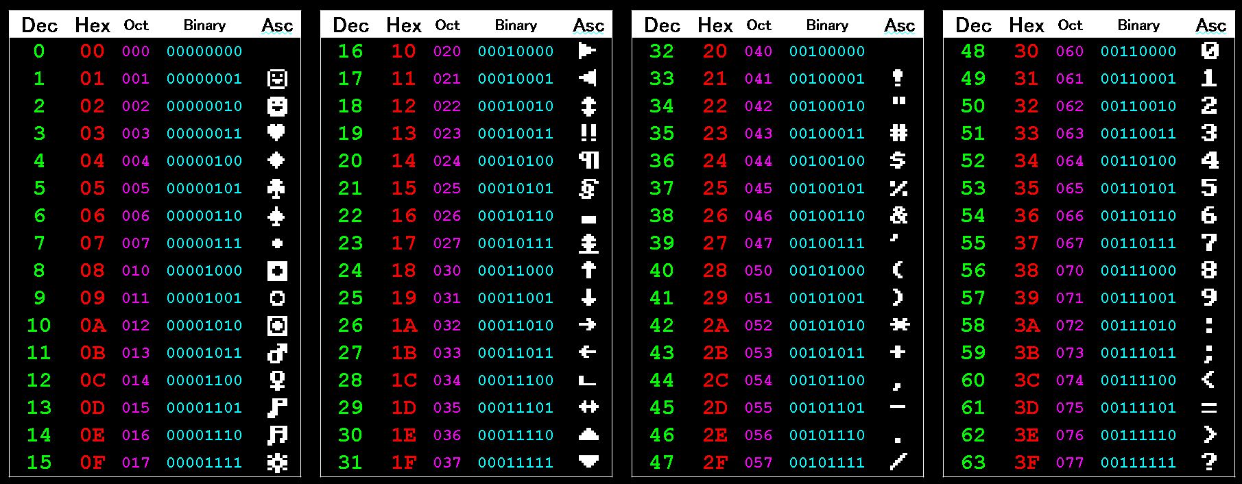
Decimal
Decimal is what we're used to - the 0-9 numbers on our clock, our
receipts, and our normal calculator.
It's known as Base 10, as each 'digit' has a value of 0-9.
Binary
Binary is Base 2. Each digit can only be 1 or 0.
"01" in binary is 1 in decimal, "10" in binary is 2 in decimal, "100"
is 4, "101" is 5 and so on.
This works better for computers, which tend to work in only 'Off' or
'On'.
In Assembly, Binary is often shown starting % . You may see 2 in binary shown as "%00000010", though other assemblers used different terminology, so you may see the same value as "00000010b" or "0b00000010".
Hexadecimal
As computers work in Binary, it's hard to make 10 or 100 out of
base 2. Hexadecimal is the way computers combine binary bits into
digits we can easily use in our source code.
Hexadecimal is 'Base 16'. It uses the normal digits from 0-9, then
uses letters 'ABCDEF' as 'digits' for 10-15.
"&10" in hexadecimal is "16" in decimal!
Hexadecimal is often shown starting with a "$" or "&", depending on your assembler. You may see the Decimal value 31 shown in hex as "$1F", "&1F".
Byte (Bytes)
A byte is 8 bits. It can go from 0 to 255 in Decimal, which is
$00 to $FF in Hexadecimal, or %00000000 to %11111111 in Binary.
A signed byte goes from -128 to +127 in Decimal.
A byte is the smallest unit of memory in a system. Registers on an 8 bit system work in bytes, and each CPU memory address refers to a byte of data. Address $0000 is the first byte of memory, and $0001 is the second, and so on.
Kilobyte
A Kilobyte is 1024 bytes. Why isn't it 1000? Well, because everything in computing is binary, 1000 wouldn't be very convenient. 1000 in hex is $3E8, but 1024 is a much more tidy $400!
Our 8 bit machine with its 16 bit address bus has a memory limit of 65536, 64 Kilobytes (64K).
Bit
| A bit is a single binary number 1 or 0, there are 8 per
byte. Bits in a byte or word are numbered backwards from right to left. In a byte, Bit 0 is the least significant (with a value of one), Bit 7 is the most significant (with a value of 128). |
 Numbered Bits in a Word and their respective value. You'll need to know the position numbers for bit testing commands, and reading hardware documentation. |
Nibble (Nybble)
| A Nibble is half a byte, that's 4 bits. Note: There are always two in a byte, there is no such thing as a system that has a 1 nibble register, or 1 nibble per memory address. The unit 'Nibble' is of course a pun on Bite and Bit, disappointingly there is no such unit as a 'Munch'! |
 Nibbles in a byte. Nibbles are always 4 bits, so there are two per byte. |
Word
A word on the Z80 goes from 0 to 65535, or $0000 to $FFFF in
Hexadecimal.
A signed word goes from -32768 to +32767.
Compare command and branches
| Basic command | Comparison | 6502 command | Z80 equivalent | 68000 equivalent |
| CMP Val2 | CP Val2 | CMP Val2,Val1 | ||
| if Val2>=Val1 then goto label | >= | BCS label | JP NC,label | BCC label |
| if Val2<Val1 then goto label | < | BCC label | JP C,label | BCS label |
| if Val2=Val1 then goto label | = | BEQ label | JP Z,label | BEQ label |
| if Val2<>Val1 then goto label | <> | BNE label | JP NZ,label | BNE label |
| Lesson
1 - Getting started with Z80! Lets get started with the Z80!... we'll learn the basics of the Z80 Cpu, and learn some basic commands for moving values into registers and simple mathematics. |
 |
 |
|
Code Comments
| There will be times we will want to put notes within our
code so we can remember how it works. These are known as
'Comments' or 'Remarks' (REM statements).
While the syntax varies depending on your assembler, comments in assembly usually start with a semicolon (;). They can be on a line on their own, or at the end of a line of code. After the semicolon, the assembler will ignore the rest of the line, so adding a semicolon to a line of code will quickly disable it. These are totally optional, they make no difference to the resulting program, but you will probably find them essential to help make the function of the code you're writing clearer, as when you're debugging it in a few weeks, or trying to reuse part of your old code many months later, you'll benefit from having spent the extra time to add at least a few comments to your code. |
 Code comments can be a whole line, or after a command. On most assemblers a comment starts with a semicolon (;). |
 |
To get
started, you can download my DevTools, These contain build
scripts to get you started running programs on the system you're
interested in as quickly as possible. The examples we'll see today should work on most of the systems the build scripts support. |
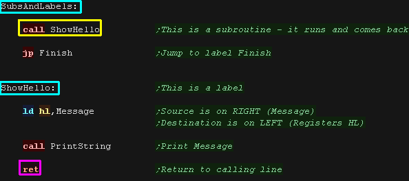
Subs And Labels
| Take a look at the example to the
right. Notice "SubsAndLabels" and "ShowHello"? These are Labels. These are "destinations" for Jumps, Calls and other commands. Labels are always at the far left of the source code. Normal commands are indented with a tab or a few spaces. "CALL" is the equivalent of the basic command "GOSUB" - it jumps to a subroutine. "RET" is the equivalent of "RETURN" |
 |
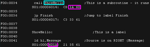
| Here's the resulting build
listing. "ShowHello" ends up at memory position 601A... the Call command uses this as a destination (It appears as 1A 60 as the Z80 is "Little Endian" and reverses the bytes) Don't worry about this if you don't understand it at this stage! |
 |
| Here is the result, we've shown our hello message to the screen. |  |
 |
We've got a
program on screen Yay! Of course we've just got started, and actually some 'pre written' code did all the work of showing the text to the screen. Don't worry, we'll learn all of that in good time! |
Register Loads
| The CPU has a very small amount of built in
memory to remember parameters for the calculations, usually just
a few bytes (depending on the system).
These are known as "Registers"... they are our 'short term storage'. It's much faster than RAM because it's inside the CPU but we have very few registers, so we have to use the slower normal memory a lot. The 8 bit Z80 has a lot more registers than the
6502, They have names like A B C D E H and L... certain pairs
can be used together to make a '16 bit pair'.
|
 Registers are 'short term memory', just a few bytes are available. RAM is 'Long term memory' many Kilobytes or even Megabytes will be available. |
| LD
is the LoaD command. On the Z80, the source (the hexadecimal value &69) is on the RIGHT... the destination (the register A - known as the Accumulator) is on the LEFT. The & tells the assembler we want to use Hexadecimal A fixed number value like this is known as an immediate. |
 |
| The Accumulator has been loaded with Hex value &69 |  |
| &69 in HEX is the same
value as 105 in decimal, or %1101001 in binary the & at the start of 69 tells the assembler this is HEX 69, not DECIMAL 69 |
 |
| Lets load more values! Here' we've loaded A with decmal -1 (Minus one) We've loaded B with decimal 69 We've loaded C with binary value 11110000.... the % specifies that this value is binary. Finally, We've loaded D with decimal 255. |
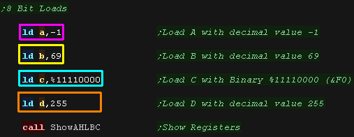 |
| Here are the results! Notice -1 and 255 have the same Hex value... why? read on! |
 |
Signed Number
|
A signed number is a number that can be positive or negative. An Unsigned 8 bit number can go from 0 to 255 but a signed number can go from -128 to +127. The way signed numbers work in assembly is odd, and exploits a 'quirk' of the way the processor registers work. A byte value in an 8 bit register can only go from 0 to 255. If we add a large number to a byte (for example adding 255 to 128) the byte will 'Overflow' going over up to 255, and wrapping back to 0. Therefore adding 255 to an 8 bit register is the same as subtracting 1! So 255 is effectively -1, 254 is effectively -2 and so on. The processor doesn't 'know' whether the 255 in a byte is -1 or 255 and it doesn't need to. We use special Condition statements for signed and unsigned numbers, and we code according to whether our byte is signed or not. Don't worry if that sounds odd, it will make more sense later! Converting a positive to a negative is easy. In code we flip all the bits via an XOR / EOR or other special command (like CPL), and add one to the result with an INC or ADDQ (or equivalent). This is known as Two's Complement. For Example: Let's look at converting 1 to -1. Our register starts with a decimal value 1. After the bits are flipped and one is added this will result in a decimal value of 255 ($01 converted to $FF in hexadecimal). On our calculator we take the maximum value plus 1 (256 for a byte, 65536 for a word) and subtract the number we want to negate. |
 -1 in HEX is &FF in 8 bit, &FFFF in 16 bit and so on.  The byte Hex value is the same for Decimal 255 as -1 (&FF) |
| If you don't understand Negative numbers yet, don't worry too much, we'll see them far more in thw future, and it will start to make more sense the more practice you get. |  |
16 bit Register pair Loads and transfers
| We can load in 16 bit pairs BC,
DE and HL
in the same way. These can take values 0-65536 (&0000-&FFFF in hex) |
 |
| Here are the results (Shown in Hex) |
 |
| We can also transfer 8 bit values between registers. Once again, the source is on the right, and the destination is on the Left it should be noted that LD can only transfer 8 bit registers, we cannot transfer DE to HL in one command. |
 |
 |
Memory Writes and Reads
| We can work with memory addresses too! Compare the two commands here... The first command is what we saw before - We loaded HL with immediate value &C000 Notice the second command has the &C000 in brackets?... this tells the assembler we're not loading &C000, we're loading from ADDRESS &C000 - so the value for DE is loaded from memory address &C000! |
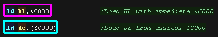 |
| We can use a memory address as a Source or Destination in this
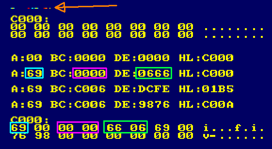
way. Here we've hoaded A with hex value &69 and stored it to memory address &C000 Next we've loaded BC from address &C002 then we've loaded DE with Hex Value &666, and stored it to address &C004 |
 |
| We stored &69 from A to address
&C000 We loaded BC from &C002 (&0000) We wrote DE's &0666 value to &C004 (it appears as &66 06 as Little endian reverses the bytes) On the Amstrad CPC you'll notice some corruption at the top of the screen? What's that?... well &C000 is screen memory! we've written those bytes to our screen! |
 |
| Rather than specifying a numbered address, we can specify a label, and define some fixed bytes with a DB statement. |  |
| Now lets load the address of that label
into register pair HL, We can then use that address as the source by specifying (HL), and load in a byte at a time into a register We can increase the value of HL by one with INC HL (moving to the next byte in memory) Note that it's not possible to load two bytes in one go! |
 |
| We've loaded our registers from HL |  |
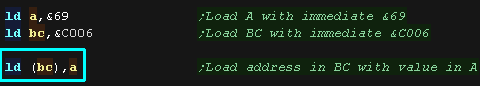
| We can also use (BC) or (DE) to
read or write the accumulator... but these cannot work with other
registers like (HL)... HL has 'Special powers' the other registers do not!!! |
 |
| We can also use (HL) as a destination. This time we point HL to memory address &C008, and write DE to that address |
 |
| We've Written DE to ram via (HL) |
 |
| Examples
like this that write to fixed memory locations may not work on
all systems, &C000 may not be RAM, or may be something super
important on some systems, So don't be surprised if this
malfunctions on the SMS or TI83! |
 |
INC and DEC... +1 and -1 ... and negatives!
| There will be many times when we want to increase or decrease
our registers by one. This will be often needed for moving through memory, or for counters. we have quick commands to do this! INC and DEC! These can INC or DEC 16 bit pairs. and INC or DEC 8 bit registers. |
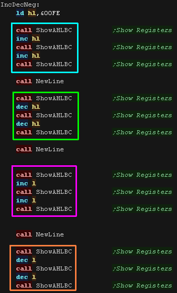 |
| We INC and DECed
the 16 bit HL pair. We can also INC and DEC the 8 bit H or L register... but if the register goes over 255 it 'wraps around' back to 0, and if it goes under 0, it wraps around to 255 |
 |
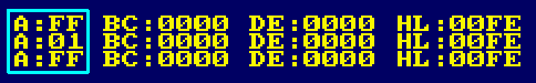
| There may be times when we need to convert an 8 bit positive
value into a negative one (or vice versa) We can do this with the NEG command. Note: There's no single command to Negate a 16 bit pair. |
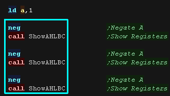 |
| Here are the results, (&FF is -1) |
 |
Add and Sub
| We'll need to do maths during our programs, and the Z80 has ADD
and SUB for 8 bit maths! the destination is ALWAYS the Accumulator (that's how it got it's name) We can specify ADD A,B (A=A+B) .... but the command ADD B is the same (A=A+B) as the destination A is implied We can also add immediate values... ADD 1 will perform A=A+1 We also have a SUB command for 8 bit maths in the same way. |
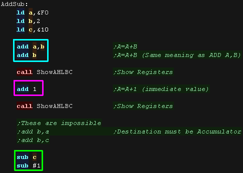 |
| we added B to A twice. We then added immediate value 1 We the subtracted C and 1 |
 |
We can add 16 bit pairs with commands like ADD HL,BC. Unfortunately, there's no SUB command for 16 bit pairs, but there is a SBC command (Subtract with carry) - we need to clear the carry first with OR A, then we can use it as a SUB... of course, if we're using a fixed negative value we can just load it into our pair, then add that negative value! |
 |
| Here are the results. |
 |
|
We're skipping
a lot of stuff here... like what the carry is for, and what OR A
means, but don't worry about it for now. We'll get to it later! |
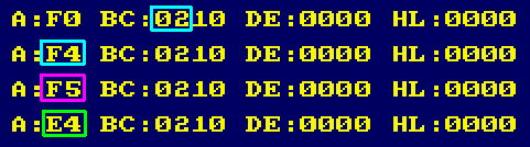
Immediate Addressing
| Immediate addressing is where a fixed number parameter is
specified as a parameter after the Opcode. This could be a single byte for an 8 bit register, or a 16 bit value for a pair. We can use Decimal, Hexadecimal, Binary or even (if we really want) maybe Octal!... the syntax to specify these will vary depending on our assembler, but VASM uses & for Hex and % for Decimal. |
 |
| The registers will be loaded with the values we specify |
 |
Register Addressing
| Register addressing is another we've already seen, it just
refers to where the source or destination parameter is a register. Note, we cannot transfer HL to DE in one go, we need to move the two parts in two commands. It's also worth noticing if we want to swap the H and L part of the HL pair, we need to use another register (in this example, the Accumulator) as a temporary store. |
 |
| Here we've transferred HL to DE, and Swapped the two parts of HL |
 |
Extended Addressing
| Extended Addressing refers to a 16 bit address used as a
destination, either for a jump or for the address to load or store
a parameter. The parameter will be specified in brackets (##) to identify the value is not an immediate. We can load and store 8 bit values to fixed addresses via the accumulator in this way. We can store and load 16 bit pairs using BC , DE or HL |
 |
| We've stored two bytes to
&C000, then loaded them into BC |
 |
Relative Addressing
| Relative addressing is where the parameter is "Relative" to the
current running line of code. This is used in the Z80 in the "Jump Relative" command (JR), this takes an 8 bit signed byte offset (-128 to +127) relative to the current Program Counter position (the position AFTER the JR command) Actually we usually just specify a label, and the assembler works our the actual jump. JR is slower than JP, but it saves 1 byte of memory as it's command is smaller, but if we need to jump 128 or more bytes away, we'll need to use JP. |
 |
| Here are the results! |
 |
Register Indirect Addressing
| Often we'll want to use the address in a 16 bit pair as the
source, We'll specify a pair in brackets, and the address i n not
the value in the register itself. The register pair will be
specified in brackets. Here we've stored HL to (HL) and stored DE to (HL) using address "TestRam" We've loaded A from (BC) using address TestRam We've then loaded A from (HL) and loaded BC from (HL) using address "TestRam" |
 |
| Here are the results |
 |
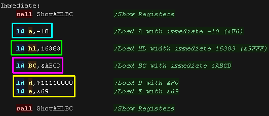
| It's not just load and store , (HL) can be used with other
commands! Here we use the value at the address in (HL) as a value to add to the accumulator. Only (HL) can do this, (BC) and (DE) cannot. |
 |
| Here is the result, we added 6 via (HL)
to A |
 |
| This even works with Jumps!... we can load a destination address in HL, and use JP (HL) to jump to that address | 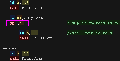 |
| Here is the result |  |
 |
Wondering
which addressing modes are available with which commands? That's
what the CheatSheet is for! You can check out all the commands available, and what addressing modes and registers they can use... of course you can also just try it, if the command doesn't exist, your assembler will tell you! |
Indexed Addressing
| Indexed addressing is similar to Register Indirect addressing,
however rather than just using the address in a register, the
address in a register is used, plus a fixed numeric value. This command uses one of the two special index registers (IX or IY) plus a displacement offset are specified after the register. The displacement is an 8 bit byte, so has the possible range -128 to +127. This allows IX or IY to be used as a 'Base' for multiple commands, as the offsets don't affect IX or IY, Often this will be used to point IX or IY to a block of data (For example the settings a sprite in the game) and then a subroutine will use offsets within that data... By pointing IX or IY to different objects, the subroutine will process a different object each time it's executed. Here We've loaded IX and IY with some test addresses. We use this to store A and BC to IX with an offset. Other commands can also use IX and IY... here we've used IY with INC and DEC! |
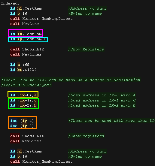 |
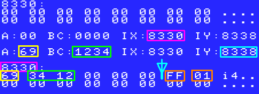
| Here are the results, We loaded A to address IX and BC to IX+1/2. We then DECremented IY and INCremented IY+1! None of these commands changed IX or IY! |
 |
| IX and IY take more memory and are slower than other registers,
but if we need a few extra for special purposes, we can actually
use the 8 bit parts of IX and IY for anything we want! There names are different to usual: IX is made up of IXH and IXL IY is made up of IYH and IYL. |
 |
| Here are the results. |
 |
| Commands
using IX and IY take up more bytes than normal commands, so they
are slower, but if you need a value occasionally, they're faster
than using memory, so they make handy loop counters, or other
'occasional use registers' |
|
Implied Addressing
| Implied addressing refers to the use of commands which take no
parameter, as their destination is implicit in the command. This usually means the command will apply to the Accumulator. Examples of this are NEG - which alters the Accumulator, and CCF which flips (Compliments) the Carry Flag |
 |
| We've Negated the accumulator, and Complemented the Carry Flag | 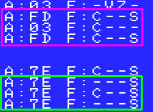 |
Bit Addressing
| Bit Addressing is used by a special set of commands which work
with registers at the bit level. These are: SET - Sets a bit to 1 RES - Resets a bit to 0 BIT - Test a bit (sets the Z flag) These take a number from 0-7 representing the bit we want to work with, and an 8 bit register. |
 |
| Here we've set and reset a variety of bits in registers! |
 |
|
You may not understand all these yet, but that's OK! You probably won't need all these in your first programs anyway, and when you get to the stage you do need them, they'll start to make more sense... We'll see these all again in later lessons anyway! |
Flags Register / Condition Codes
| Whenever we do a calculation, the flag
register will store the 'answers' to some questions we may ask.
For Example: Z Flag Was the result Zero? All these 'Flags' are stored in a special 8 bit register 'F'
|
 Flags can be set (1) or Clear (0). |
||||||||||||||||||||||||||||||||||||
| The flag register contains 8 one bit 'states'. Each keeps track
of an attribute of the last command we performed.
For Example: If we do a compare like "CMP #0", the Z flag will be set if the accumulator is zero. The S flag will be set if the accumulator is negative. We can use these later with conditions to branch to different parts of our code.
The main ones you will need to know about are Carry (C) and Zero (Z). Sign (S) is also useful in some cases, but you'll probably never actually need to know about P/V, H and N. On the Z80 many commands do not change the flags. You need to check if the command you're using actually updates them. For Example: "DEC B" will correctly update the zero flag, "DEC BC" will not, so with "DEC BC" you'll need to manually check if B and C are zero. This can be done with "LD A,B OR C". |
|
||||||||||||||||||||||||||||||||||||
| The Z80 has a variety of condition codes, which can be applied
to Jumps, Calls and Returns, We'll try these out in this lesson! |
|
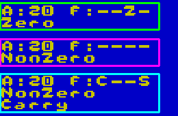
The Zero Flag
| Here we're using DEC A to decrease the
Accumulator... this command alters the accumulator and sets the z
flag based on the value in A We then use ZR NZ, to jump back and repeat ONLY if the Zero flag is Not set (NZ=Not Zero) |
 |
| Here are the results, we've repeated until A reached zero |  |
| If we want to do a loop, you may want to use DJNZ
- it uses B as a loop count This deceases B until B reaches Zero, repeating until it does. Note it does NOT set the flag! |
 |
| Our Loop repeated until B reached zero Note the Z flag never changed... not all commands alter the flags |
 |
| Not all commands set the flags! LD does not set the Z flag, but SUB does! |
 |
| the LD command did not change the flag. The SUB command did! |
 |
Jumping and CALLing!
| We have two ways we can act upon a flag. We can do a jump with JP or JR - This will jump to a new part of the program like the basic statement "IF ??? THEN GOTO ???" we can do a call with CALL - this will run a subroutine and then return like the basic statement "IF ??? then GOSUB ???" |
 |
| Here are the results |
 |
The Carry flag
| The carry flag is used store bits which are 'pushed out of' a
register. It's very much like the Carry or Borrow you would write when doing Long addition on paper |
 |
| Here we're repeatedly using the ADD command
- this will set the Carry flag when A goes
over 255, or under 0 (as a borrow) C means the Carry is set (or borrow) NC means there is No Carry |
 |
| We repeatedly added to A... when A wrapped back to zero, the Carry was set |  |
| We can use HL with ADD and ADC to combine two 16 bit words to make
one 32 bit one! Here we're repeatedly adding and storing the values to memory - effectively counting in 32 bits. |
 |
| Here we counted 32 bit values in little endian: &0001FFFE &0001FFFF &00020000 &00020001 |
 |
| We can do the same with SBC HL. Remember, there's no 16 bit SUB HL command, so we clear the carry with OR A to clear the carry |
 |
| Here we counted 32 bit values in little endian: &00020001 &00020000 &0001FFFF &0001FFFE |
 |
The Overflow and Sign flag
| You may remember that an usigned byte will go from 0-255 But in decimal a signed byte goes from -128 to +127... -128 is &80 in Hex, +127 is &7F in hex This causes us a problem... if we add 1 to +127 (&7F) , it will roll round to -128 (&80)... ruining our signed number! This is what the oVerflow flag is for... it allows us to detect when an addition or subtraction has 'Broken' our signed number. It's also a good time to look at the Sign flag, which identifies if a signed value is negative. this effectively matches the top bit of the register (Bit 7) |
 |
| We can test the Sign flag with M (Minus)
and P (Plus) We can test the oVerflow with PO (No overflow) and PE (Overflow)... the odd names are because the overflow flag also doubles as a parity flag - we'll look at that in a moment |
 |
|
The oVerflow
flag and the Parity flag are the same flag!!! What's that mean? well some commands (addition / subtraction) use it as a oVerflow, and others (Bit operations) treat it as a Parity... Want to check how a command uses it? get the CheatSheet! |
The Parity flag
| You'll probably never need the parity flag. Parity can be used for 'checking' data read from media like tapes, as a 'checksum' for the bits read in. On the Z80 the parity is set by logical ops and bitshifting commands (We'll cover these more later) The parity flag is set if the number of 1 bits in the register are even, and zero if they are odd. We can test these with PE (Parity Even) and PO (Parity Odd) |
 |
| The Parity flag (P/V) is set when the count of ones in A is Even. |  |
Comparisons with CMP
| The flags aren't just useful for mathematical operations, we
also use them for comparison statements! the CP (ComPare) command sets the flags like a SUBtract command, but doesn't change registers. This sounds weird, but we can effectively use it to set the flags, then use the flags to jump like an IF statement in basic. Z will be set if the difference is zero. C will be set if the Accumulator is smaller (more Chibi!) if we do CP D then we can use the Z,NZ,C and NC flags like the following IF statements:
|
 |
||||||||||
| Here we've tested the Zero flag by comparing to immediate 32 (CP 32) and B (CP B) we've then compared to B - and executed subroutines based on if the Z or C flag are set |
 |
| These
conditions will work for unsigned numbers, but unsigned numbers
will be more tricky. S and V flags will be different if A is lower than the compared value, and S and V will be the same if A is higher Fortunately, if you're writing little games this may be something you won't have to worry about |
|
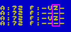
BIT commands for bit testing!
| If we want to test a bit of a register, but don't want to change
the register itself, we can use the BIT command. This takes a bit number (0-7) and a register, and tests the bits. |
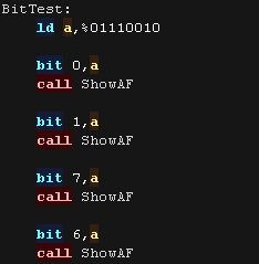 |
| Here is the results, we tested the bits of the accumulator and
set the Zero flag accordingly, The Accumulator was not changed in the process. |
 |
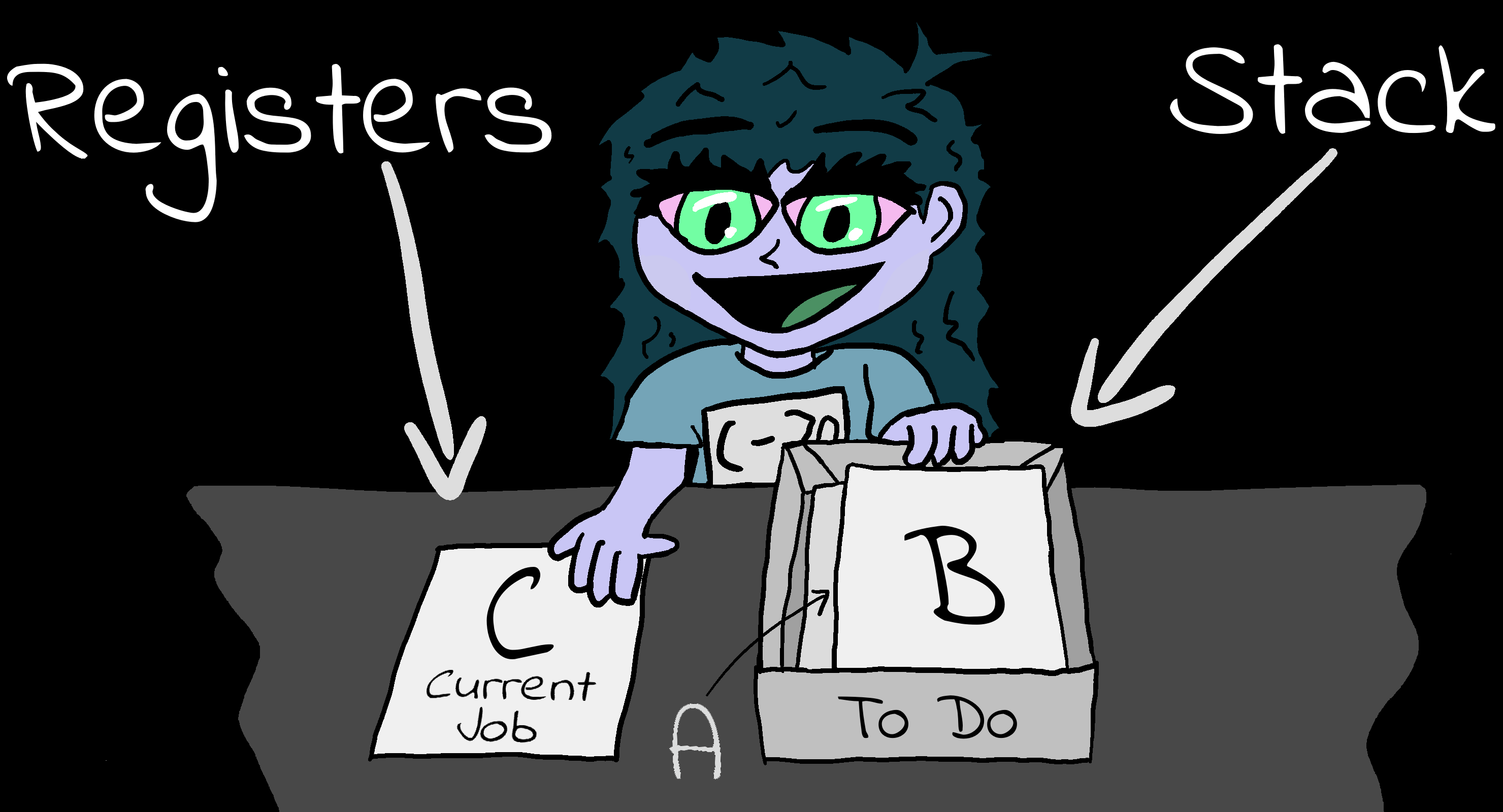
The concept of the stack
| The stack is a temporary store for data. We
don't have very many registers, and there will be times (like in a
subroutine) where we need to put all the current data to one side
and do another job for a while, then bring all the old data back.
This is what the Stack is for. When we have some data we need later, but need to do something else first, we put it on the stack. Later we'll take it off and use it again. You can think of the stack like your office in-tray. We can put jobs in our 'in tray' when we want to do them later, and pull them out when we want to work on them again. We can put as many items into our in-tray as we want, but we have to take them off the top of the in-tray, not from the middle. The same is true of the stack. We can put many items onto the stack, but they always go on top of the last one, and we have to remove them in the reverse order, taking out first the last item put in. This is called a Last In First Out stack. This means we put items 1,2,3 onto the stack and we'll take them back in order 3,2,1. The current position in the stack (the top of our in-tray) is marked by the Stack Pointer (SP). Technically speaking, the stack actually goes DOWN in memory. If the Stack Pointer starts at &C000 and we put (PUSH) two bytes onto the stack, the Stack Pointer will point to &BFFE. When we take the bytes off (POP) the Stack Pointer will point to &C000. The Stack Pointer always points to the first empty byte of the stack. |
 |
||||
Lets
suppose we have a value in A ... we need the value again later,
but we need all our registers now too... what can we do? Well
that's what the stack is for, it's a temporary store!
The stack is like a letter tray - we can put an extra sheet on the top of - and take it off later, but we can't get one from the middle, so we always get the Last one we put in - this is known as LIFO - Last in First Out We use PUSH and POP to push a new item onto the stack, and pop it off later. Lets look at two examples, and see why we want the stack! Suppose we have a Call 'PrintChar' which will print the character in A ... and another call 'DoStuff' which will change all the registers - how can we keep A the same before and after this 'DoStuff' command? Well, we could save A to some temp memory - or let the stack take the slack! Both these do the same thing, but commands like LD (temp),a takes 3 bytes, and PUSH AF takes only 1.. and it's faster! also you no longer need that Temp: db 0 ... so that's another byte saved! the stack always works in 16 bit - so even if you only want to save B - you'll have to PUSH BC - but don't worry , it's so fast you won't mind! note: the F in AF is the 'Flags' (the Z NZ C NC in comparisons) - they're saved with A when you do a push. You can push lots of different things onto the stack, but remember they will come out in the same order... you can even do PUSH BC then POP DE to copy BC into DE |
This is just an example... Don't type it in!
|
Backup and restoring values with the stack.
| Lets do an example of the
stack! Here we've loaded a first test value &FEDC into HL and Pushed it onto the stack. Next we loaded &9876 and Pushed that onto the stack. We then Popped HL off the stack, getting back &9876 Finally we Popped the first value back, but this time into BC. Of course we can push and pop our other registers - the Accumulator and Flags are joined into a 16 bit pair AF |
 |
| Here are the results... In this example the stack pointer was
set to &DFF0. We pushed various items onto the stack and restored them - we can see these appear on the stack. Notice how the SP goes Down as we push, and Up as we pop |
 |
|
In the
screenshot above it looks like the items 'disappear' from the
stack when popped. This isn't actually the case, only the SP
changes. It's the Test code "ShowTestStackB" which 'accidentally' removes the items from the stack... we'll learn why soon! |
The Stack and Subroutines
| The stack is fundamental to the workings of the Z80... It's not
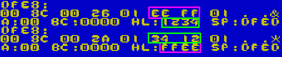
just used by our code, but by the CPU itself! Whenever we call a subroutine, the CPU needs to know where to return after the subroutine finishes (the RET command) Whenever we use a CALL, the address of the next command is PUSHed onto the stack. Whenever we RETurn, a word is POPped off the stack into the Program Counter (the current running line) Here we've called a Subroutine, and Pushed &1234 onto the stack, then called another sub and Pushed &5678 onto the stack. Each time we call a subroutine the Return Addresses will also be pushed onto the stack |
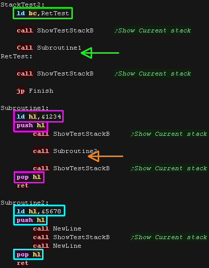 |
| Here is the result. When we called our sub, the Return address was on the stack, we then pushed &1234 onto the stack. We called our second sub, the Return address was on the stack, we then pushed &5678 onto the stack. |
 |
| CLEAN
UP YOUR MESS! Because the RET command needs the stack to be in order, you need to make sure your subroutine leaves the stack in the state it found it, otherwise the RET command will get some junk data, not the correct return address and your program will crash! |
|
Special Stack Commands
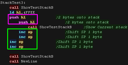
| There are a small, but varied range of commands we can use with SP
(See the cheatsheet for more
details) We can alter the stack pointer, without removing items with a POP by using the INC SP command... here we pushed HL onto the stack twice, and reset the Stack Pointer (SP) with 4 INC SPs |
 |
| Here is what happened... we added two items to the stack, moving
the SP down by 4 to &DFEC We then INC SP adding 4, setting it back to &DFF0 |
 |
| Lets alter the SP via HL... This time we'll transfer
SP to HL, we do this via an ADD HL,SP (there's no LD
HL,SP command!) we then DEC the SP, and transfer it back to the SP with LD (SP,HL) We can also back up and restore the SP to and from memory. |
 |
| Here are the results. |
 |
| There may be times we want do do things quicky with the item on
the top of the stack. We can swap HL with the item on the top of the stack with EX (SP),HL. This could be handy for getting the return address during a call, and because it's EXchanging the item with HL, the old HL will now be on the stack, so if we do it twice, the old value will be restored. |
 |
| Here are the results |
 |
| If
we're feeling super brainy, we can use the Stack to do clever
things, like passing parameters, or even fast reading and
writing (Stack Abuse / Stack Misuse). These are quite tricky, and not something to worry about when you're getting started, but they're things you may want to look into later. Find out more here |
|
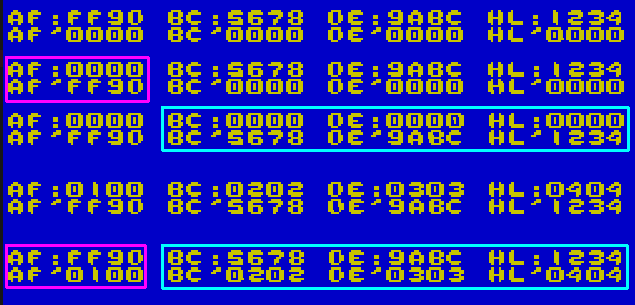
Shadow Registers
| Need some more registers
for a while, but don't want to use the stack? The Shadow Registers
are here to answer your needs! AF,BC,DE and HL actually have a 'secret alternate' versions known as the 'Shadow registers'... known as AF',BC',DE' and HL' There are two commands to use these EX AF,AF' swaps the Accumulator and Flags, EXX swaps all the others (there's no way to use just one of the BC,DE,HL shadow regs) |
 |
| Here are the results. |
 |
| It doesn't use the Shadow registers, but there is another
Exchange command. EX DE,HL will swap HL and DE... Why would you want to do that? Well there's lots of special commands that can do things with only (HL) - this is a quick way to switch over to DE for a while to use those commands with the value in that register. |
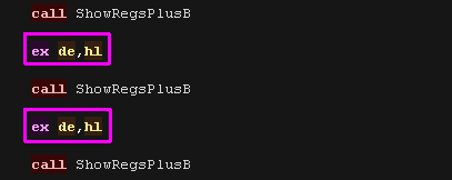 |
| Here are the results. |  |
|
With great
power comes great crashes! The most common use for the shadow registers is during an Interrupt routine, so if you've not written your own (or know they aren't used), then using the Shadow Registers could cause crashes or other problems! As a beginner, you probably don't want to use them at this stage, but you need to at least know they are there! |
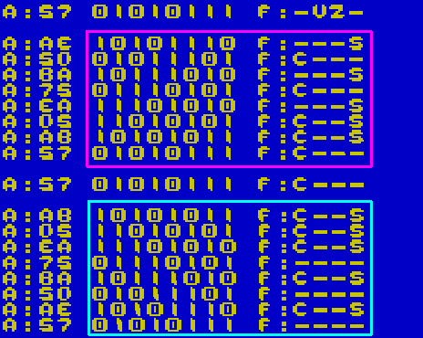
Rotation of bits within the register with RLC and RRC
| There will be times we want to move
the bits around registers. RLC Rotate bits in a register Left and Copy the top bit to the Carry. RRC Rotate bits in a register Right and Copy the bottom bit to the Carry. |
 |
| We've rotated Left
and Right. While the bit that's leaves the register is copied to the carry, it also immediately returns. This means when we rotate 8 times, we end up exactly where we started! |
 |
SLA and SRA for halving and doubling signed numbers.
|
Bit shifting is
magic!... when we shift the bits to the left we double the value
in the register, When we shift it to the right we halve it.... Don't believe me? Try it in Windows Calculator! There's a catch though - if the number is signed, we need to keep the sign, and that's where Arithmetic and Logical shifts come in! |
| If we're shifting a signed number, we need to keep the sign
correct... to do this we use SLA and SRA. SLA Shift the bits register r Left for Arithmetic.... All new bits that appear at bit 0 contain a zero, bits pushed out end up in the carry SRA Shift the bits in register r Right for Arithmetic... All new bits that appear at bit 7 contain the same value as the old bit 7 (retaining the sign), bits pushed out end up in the carry This means the sign stays the same as we halve and double, but of course if we shift too much, we'll lose the value, as the byte can only contain -128 to +127... but we can shift those 'carry' bits into another register to work in 16 bits or more.... we'll see that in a moment |
 |
| The new bits added by SLA were Zero The new bits added by SRA were all, in this case 1 - as the top bit was 1 before, if it had been 0 the bits added would be 0 |
 |
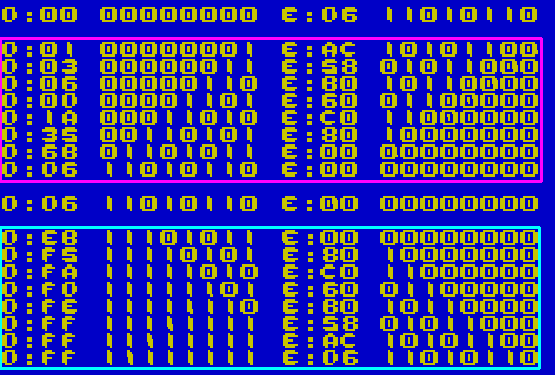
SRL for halving unsigned numbers, and SLL for... er... something!
| If we want to halve an unsigned number we can use SRL
... This shifts the bits to the right, All new bits that appear at bit 7 contain a zero, bits pushed out end up in the carry. SLL is weird, it shifts to the left, but all new bits are a 1... You probably should avoid relying on command, as it's "undocumented" and isn't supported by the eZ80. If you actually want to double an unsigned number, you can use SLA |
 |
| Here is the results of SLL and SRL |
 |
| SRA cannot be
used on unsigned numbers, But SLA will correctly double either
signed or unsigned numbers! On most CPU's Logical shift left would correctly double an unsigned number, but on the Z80 it does not, that's because it is an undocumented opcode! |
|
Moving bits into another byte with RR and RL
| Doubling and halving an 8 bit value is interesting, but there will
be times we need to work with values over 255, The solution is to use 2 (or more) registers, and shift the carry into the second register, We can do this with RL (Rotate Left) and RR (Rotate Right) - these push the value in the carry into the specified register. We can use SLA and RL to double a signed 16 bit value, and SRA and RR to halve a signed 16 bit value. |
 |
| We've used D as a high byte, and E as a low byte We've shifted Left with SLA and RL, and right with SRA and RR. We could also use SRL and RR for unsigned numbers if we wish. |
 |
| You're
probably wondering what to do if you want to multiply by numbers
other than two... well it's tricky! Take a look here if you're feeling brave! |
|
Logical Operations
| AND OR and XOR take two parameters, and output a result. Each bit of the two sources will have the logical operation applied to each bit to produce the result. |
|
||||||||
| Logical operations can be used to alter the pixels of a bitmap
screen. Here's the effect of some logical operations on the CPC screen. |
|
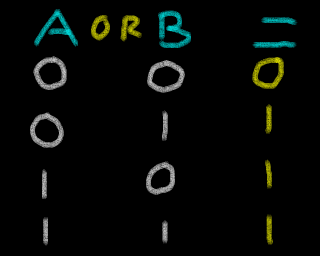
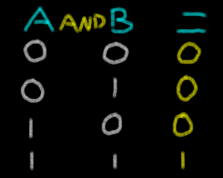
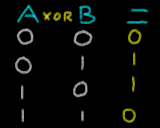


| Lets try our each of the operations! The Destination is always the Accumulator, We can use an immediate 8 bit value, or an 8 bit register as the other parameter. The Z80 offers us AND, OR and XOR (Exclusive Or) |
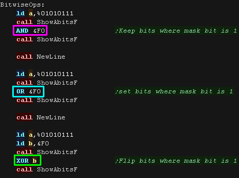 |
We tried each operation with the parameter &F0 Here are the results |
 |
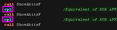
| One other related command is CPL This stands for "Complement"... Ones Complement refers to flipping all the bits. It's effectively the same command as "XOR %11111111" |
 |
 |
| Want to clear A
to zero? use "XOR A"! it does the same as "LD A,0" but takes one
less byte! Want clear the Carry Flag? use "OR A"! It clears the carry flag... REMEMBER! CCF is Complement Carry Flag - not clear! |
|
Assembler Directives
| Assembler directives are commands which instruct the
Assembler to do something. These are not converted directly to
command bytes for the CPU, instead they change the function of the
Assembler and tell it how to assemble
the code.
There are a wide range of assembler
directives, and their format will vary depending on the
Assembler, but we'll check out some of the common ones with VASM
here. You'll need to check your Assembler manual to know the commands available to you, and you'll probably only need a few of the wide range available. We'll discuss some of the general ones you're likely to need throughout this lesson. |
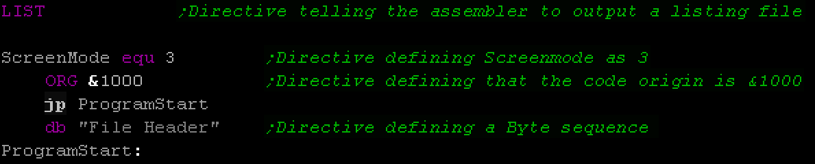 There's a huge range of Assembler directives, depending on your Assembler and syntax choice. The only thing you can do is check your Assembler's manual. |
Symbols
| A symbol is a fixed value (it doesn't change during our
code). It's the assembler that converts the symbol, the binary
file will not change whether we use the number or the symbol in our
code. EQU stands for 'EQUate' or 'EQUivalence', it tells the assembler the symbol has the same value as the number which follows. The exact syntax of the command varies depending on your assembler. In VASM, EQU statements have to be at the far left like labels. Symbols are actually very similar to labels - Labels are given the numeric value of the line they are defined. Symbols are given what ever number we give them! Here are some sample symbols! |
 |
| The symbols were loaded into the registers. |  |
| Symbols can be used in our code in place of normal numbers - we can use them pretty much however we want, and they are a great way to make what our code is doing clearer to the reader. |  |
Org Statement
| When we assembler our program, the assembler will have to give all
our labels addresses. If we don't tell it anything else, these will start from &0000, but what if our program loads to a different address? We can define the position of our code with an ORG statement, this will set the address of the next line of code, and pad the file if required. If you've been using the sample headers these tutorials provided, there's always been an ORG statement hidden in the header! |
 |
| The ORG statement padded the file to the specified address |
 |
| Some
Assemblers only allow one ORG statement per program, others
allow multiple to 'pad' to a particular address mid program. Check the documentation of your assembler to find out! |
|
Conditional Compilation
|
There may be times when we want to build multiple versions
of our program from the same source. We don't want to keep two separate copies of the source files, as this would increase our developing and maintenance time, instead what we do is use 'Conditional Compilation'. By using assembler directives, such as IFDEF and ENDIF, we can define blocks of code which will only assemble if a symbol is defined. By defining only certain symbols, we can enable and disable these blocks, changing the code that is assembled, and the resulting program. Enabling and disabling symbols can be done by simply putting a semicolon (;) at the start of the line, turning them into comments, or symbols can often be defined on the assembler command line, meaning we can run different scripts to build different versions of our code. |
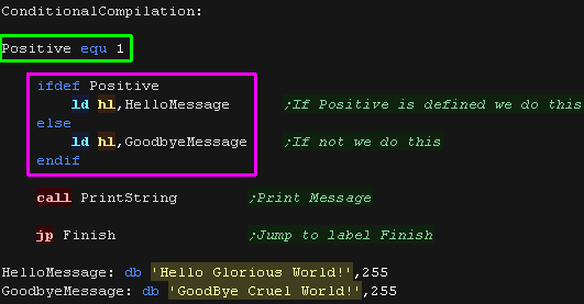 |
| Here the Positive symbol was defined, so HelloMessage is shown |  |
Defining bytes of data and aligning.
| There will be many times when we need to define bytes of data in
our code. Examples of this would be bitmap data, the score of our
player, a string of text, or the co-ordinates of an object.
In VASM we can define a byte with DB, a word with DW or space of n bytes with DS n .... if we want to fill the space with byte b we can use DS n,b |
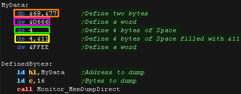 |
| The bytes have been defined in ram |
 |
| There may be times we want to control the position of the bytes, for example we may need our data to be aligned to an even byte boundary (&1000,&1002,&3004 etc) or may need the bottom byte to start from zero (&1100,&1300, &FE00 etc) This is useful for times we're reading data from lookup tables, and when we want to only increase the low byte of a 16 bit address ("INC L" is faster than "INC HL"). We can do this with the ALIGN command - this allows us to align with a certain number of 'low bits' as zero. Here we've aligned to an 8 bit bounday - We've used this to make a Look Up Table, we can now load L with a number, and read a byte from the address - and convert a number to a letter of the alphabet! |
 |
| Here are the results |
 |
Vector Tables
| A special kind of lookup table is a vector
table. This is a list of addresses we can jump to.... We can use this to define a set of 'Numbered commands' We load a pair of bytes from entry A (we multiply A by 2 by adding twice - as there's two bytes per entry) We load in the two byte address and jump to that address |
 |
| We can use this routine to run numbered commands from the
accumulator! |
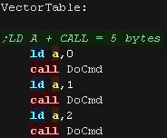 |
| Here are the results |
 |
| If the low area of our system is Ram (&0000-&0100) we can
"Make our own command" by taking over one of the RST's We get the return address from the stack, read the byte that comes after to get the command number (updating the return address once we have done) - this is now our command number! This is known as 'Relocatable code' - we copy it to a different address and it still works fine, this is because there's no absolute jumps that will cause a problem. |
 |
| Here is the result! While the claim a 'Cow says woof" is a little dubious, the program worked fine! |
 |
Macros
| A Macro is a bit like a symbol. It defines a set of commands
that are given a 'name'.
We can then use that name in our code and the assembler will replace it with all the commands we defined. The Assembler will use our definition to produce the resulting program with the contents of the macro replacing this. It's a bit like making our own commands. It saves us copying the same code over and over and it saves a bit of time, rather than writing a subroutine. The syntax of a macro definition depends on the assembler. You'll need to check the documentation of your Assembler. |
 |
| Here are the results |  |
| Using
a macro to do a job will take more bytes than a sub, as the sub
only appears once in your code, whereas the contents of a macro
appears each time it's used. |
|
|
We can even use
labels in our macros, and the assembler will give them a different
'final name' each time they are used in your program! All this is specific to your assembler... so get reading the assembler manual! |
Fast Copy with LDIR
| There will be times we want to
transfer a block of data from one place to another... we could do
this with a sequence of LD A,(HL) and LD (HL),A commands, but there
is a faster way! These commands use three register pairs: HL is the source DE is the DEstination BC is the Byte Count the LDIR command will transfer a block of data, Copy BC bytes from HL to DE in ascending order. Alternatively we have the LDDR command, the LDDR command will transfer a block of data, Copy BC bytes from HL to DE in descending order. |
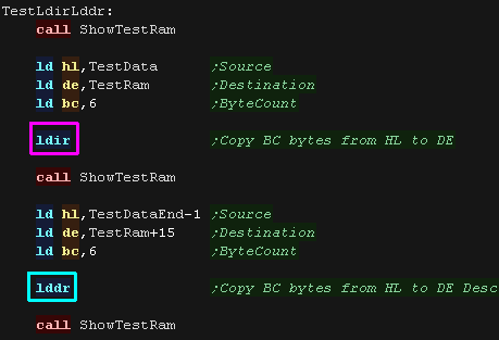 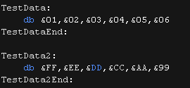 |
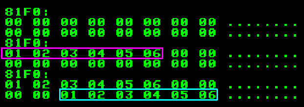
| We've transferred 6 bytes in ascending order with LDIR,
and 6 bytes in descending order with LDDR |
 |
| LDIR and LDDR are super fast, but we may need to do things after
each byte transfer. For this we have LDI and LDD, these transfer one byte and update HL,BC and DE but do not repeat. We can use this a few times, do some other work, and do our own repeat if we want... it's still quicker than a bunch of LD A,(HL) and LD (HL),A! |
 |
| Here are the results.We used LDI and LDD 3 times, so that's how many bytes were copied. |  |
Using Ports with IN and OUT
| There will be times we need to transfer data to
a device other than RAM memory. For Example: We may want to read the status of the Joysticks, or make a sound, and we use I/O ports to do this. On the Z80 we have special commands to do this.... this allows us to address the ports which connect to other devices on our computrer Things can be very different depending on the computer. On the Z80 based CPC the VRAM (Video Ram) is part of the normal memory, but on the Z80 based MSX it is separate and we have to use I/O ports to access it. Also, some systems use 8 bit ports, and the OUT (C) command will just use the (C) register, but some actually have 16 bit ports, and the command OUT (C) will actually use (BC)!.... This just depends how the Z80 is wired to the system. Here is a breakdown of how common systems are wired..
|
 The RAM addresses and I/O ports are separate. |
IN and OUT on the Sega Master System
| because ports are different for each system, we need an example
that's designed for a particular system. Lets use the OUT command to change the background colors on the SMS First we need to select a VRAM address to change - we want to select &C000 - which is Color 0 of the Color RAM We need to send these two bytes to port &BF - which is the VDP Control port.... we do this with OUT (C),r We use NOP to pause a moment - this is "No Operation" - it does nothing and is just a short delay We then send the color byte to the VDP Data port... this is &BE, so we OUT to this port via the Accumulator with OUT (&BE),A |
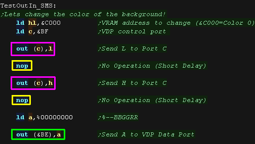 |
| We've changed the background to black... if we change the byte we
send to port &BE we'll get a different color! |
 |
| We can read in with an IN command! Joypad 1 is connected to port &DC... we can use IN A,(&DC) to read a byte from the joypad port. |
 |
| When we press the directions, the byte read will change
accordingly |
 |
IN and OUT on the ZX spectrum
| The ZX Spectrum uses 16 bit ports, but we can change the border
color with a write to any address with a bottom byte of
&xxFE We can change the color by writing a number 0-7 with OUT (&FE),A |
 |
| We've changed the border to Magenta! |
 |
| We can read in from the keyboard using IN! Each line has a different port... we can read in the line with space using 16 bit port &7FFE and IN A,(C) |
 |
| We've read in bytes... Try pressing space and see the byte change!
(Also try B N and M) |
 |
Sending lots of bytes with OTIR on the Sega Master System
| There will be times we want to send a block of data to a port...
Like LDIR for memort, we have OTIR! OTIR will transfer B bytes from HL to port (C) Here we've transferred a 16 color palette to port &BF |
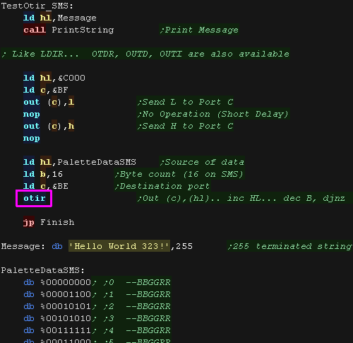 |
| We've changed our background and font color! Like LDIR... OTDR, OUTD, OUTI are also available |
 |
Sending lots of bytes with OTIR on the MSX1
| The MSX VDP is very similar to the SMS! We can select a VRAM address with the control port &99... then send data to VRAM with the data port &98 Here we select VRAM address &5800, this is the 'TileMap' (The characters onscreen) We then use OTIR to transfer 16 bytes to VRAM |
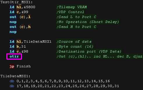 |
| Here are the results! |
 |
Interrupts and IM 1
| Interrupts are exactly what they sound like!
Sometimes a device, Like a disk or mouse, will want to send some
data to be processed RIGHT NOW!
The CPU will have to stop whatever it was doing and deal with the data. The current running program will be interrupted, and a 'sub program' will run (usually in system ROM) to deal with the interrupt. When the interrupt is done, the original running program will resume as if nothing happened. On the Z80 we can turn interrupts off in many cases. On most systems we can create our own interrupt handlers to do clever things, like make the screen wobble by moving things as the screen is drawing. There are two kinds of interrupt: Non-Maskable Interrupts (NMI) cannot be disabled. On the
Z80 NMI interrupts result in a CALL to address $0066. |
 NMI can't be stopped by Disabled Interrupts (DI). |
IM 1 on the Amstrad CPC
| Let's set up our interrupt handler. We need to make sure interrupts don't happen for a while, we do this with DI (Disable Interrupts) We transfer a jump to our interrupt handler to address &0038. The bytecode for a JP command is &C3. Once our interrupt handler is ready we turn interrupts back on with EI. We can wait for an interrupt with HALT |
 |
| Here's our interrupt handler. We switch in the shadow registers with EX AF,AF' and EXX We then set the background color to L using port &7F00 We swap H and L, so next time the interrupt runs the color will be different. We switch out the shadow registers with EX AF,AF' and EXX We Enable Interupts and return |
 |
| Interrupts on the CPC happen multiple times per screen, so this
produces a stripey pattern. |
 |
| Addresses &0000-&0038 have special commands known as
'Resets' which can jump to them (Only for multiples of 8) We can call to &0038 with the single byte command RST &38 (called RST 7 on some assemblers) Here we call it manually to force the interrupt handler to run. |
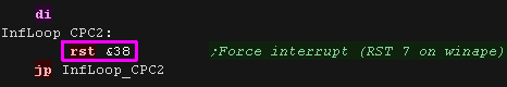 |
| Here is the result |
 |
IM 1 on the Sam Coupe
| Let's set up our interrupt handler. We need to make sure interrupts don't happen for a while, we do this with DI (Disable Interrupts) By default the &0000-&3FFF range is ROM... so we page some RAM in with port 250 We transfer a jump to our interrupt handler to address &0038. The bytecode for a JP command is &C3. Once our interrupt handler is ready we turn interrupts back on with EI. We can wait for an interrupt with HALT |
 |
| Here's our interrupt handler. We switch in the shadow registers with EX AF,AF' and EXX We change the border color with port 254 We switch out the shadow registers with EX AF,AF' and EXX We Enable Interupts and return |
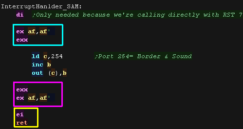 |
| The border will flash! |
 |
| Addresses &0000-&0038 have special commands known as
'Resets' which can jump to them (Only for multiples of 8) We can call to &0038 with the single byte command RST &38 (called RST 7 on some assemblers) Here we call it manually to force the interrupt handler to run. |
 |
| Here is the result The port which controls the border also controls the beeper speaker, so the result is quite noisy! |
 |
|
Systems like the ZX Spectrum can't use IM1, because
the &0038 address is not changable. The only option is IM2 (Interrupt mode 2) - It's a lot harder to set up, but can have the same effect... you can learn about it here |
| If we use DI to
stop interrupts and miss one, on some systems the interrupt will
happen as soon as we use EI to turn them back on, this is true on
the CPC and MSX, but on the Spectrum it will be missed!.... Also some systems need you to read or write a port to 'clear' the interrupt... otherwise it'll keep happening forever! This can cause problems, like our music slowing down... You need to check the hardware documentation to see what each system does |
|
 |
You guys give up, or are you thirsty for more? Lame movie quotes aside, if you want an 'alternative take' on the Z80 tutorials, you can see the old series here... or proceed to the Platform Specific series! |
| Mnemonic | Desctiption | Example | Parameters | Flags affected |
| ADC r | Add register r and the carry flag to the Accumulator A. | ADC B | 'r': (HL) (IX+#) (IY+#) A B C D E H L IXH IXL IYH IYL | S Z H V N C |
| ADC A,# | Add 8 bit number # and the carry to A. | ADC 128 | '#': 0-255 ($00-$FF) | S Z H V N C |
| ADC HL,rr | Add 16 bit register rr and the carry to HL. | ADC HL,BC | 'rr': BC DE HL SP | S Z H V N C |
| ADD rr2,rr1 | Add 16 bit register rr1 to 16 bit register rr2. | ADD HL,BC | 'rr1': HL IX IY 'rr2': BC DE SP *HL IX IY* |
- - H - N C |
| ADD r | Adds 8 bit register r to A. | ADD B | 'r': (HL) (IX+#) (IY+#) A B C D E H L IXH IXL IYH IYL | S Z H V N C |
| ADD # | Adds 8 bit value # to A. | ADD B | '#': 0-255 ($00-$FF) | S Z H V N C |
| AND r | Logical AND of bits in register r with Accumulator A. | AND B | 'r': (HL) (IX+#) (IY+#) A B C D E H L IXH IXL IYH IYL | S Z H V N C |
| AND # | Logical AND of bits in 8 bit value # with Accumulator A. | AND $64 | '#': 0-255 ($00-$FF) | S Z H V N C |
| BIT b,r | Test bit b from 8 bit register r and set the Z flag to that bit. | BIT 7,B | 'b': 0-7 (%76543210) 'r': (HL) (IX+#) (IY+#) A B C D E H L |
s Z H v N - |
| CALL addr | Call Subroutine at address addr | CALL $1000 | 'addr': 0-65535 ($0000-$FFFF) | - - - - - - |
| CALL c,addr | Call Subroutine at address addr only IF condition c is true. | CALL Z,$1000 | 'addr': 0-65535 ($0000-$FFFF) 'c': c m nc nz p po pe z |
- - - - - - |
| CCF | Complement the Carry Flag. C flag will inverted | CCF | - - H - N C | |
| CP r | Compare the Accumulator to register r. | CP B | 'r': (HL) (IX+#) (IY+#) A B C D E H L | S Z H V N C |
| CP # | Compare the Accumulator to 8 bit immediate value #. | CP 32 | '#':0-255 ($00-$FF) | S Z H V N C |
| CPD | Compare A to the byte at address HL and decrease HL and BC. | CPD | S Z H V N - | |
| CPDR | Compare A to the byte at address HL and Decrease and Repeat | CPDR | S Z H V N - | |
| CPI | Compare A to the byte at address HL and increase HL but decrease BC (Bytecount). | CPI | S Z H V N - | |
| CPIR | Compare A to the byte at address HL and increase HL but dec BC (Bytecount) and Repeat until a match occurs or BC=0. | CPIR | S Z H V N - | |
| CPL | Invert all bits of A (this is known as 'One's Complement'). | CPL | - - H - N - | |
| DAA | Decimal Adjust Accumulator (Binary Coded Decimal) | DAA | S Z H V - C | |
| DEC r | Decrease value in 8 bit register r by one. | DEC B | 'r': (HL) (IX+#) (IY+#) A B C D E H L IXH IXL IYH IYL | S Z H V N - |
| DEC rr | Decrease value in 16 bit register rr by one. | DEC HL | Valid registers for 'rr': BC DE HL IX IY SP | - - - - - - |
| DI | Disable Maskable Interrupts | DI | - - - - - - | |
| DJNZ ofst | Decrease B and Jump if NonZero to address offset #. | DJNZ label | 'ofst': -128 to +127 | - - - - - - |
| EI | Enable Maskable Interrupts. | EI | - - - - - - | |
| EX (SP),HL | Exchange HL with the top item of the stack | EX (SP),HL | - - - - - - | |
| EX AF,AF' | Exchange the Accumulator and Flags with the shadow Accumulator and Flags. | EX AF,AF' | S Z H V N C | |
| EX DE,HL | Exchange HL and DE | EX DE,HL | - - - - - - | |
| EXX | Exchange the registers BC, DE and HL with the shadow registers | EXX | - - - - - - | |
| HALT | Stop the CPU until an interrupt occurs. | HALT | - - - - - - | |
| IM 0 | Enable Interrupt mode 0. | IM 0 | - - - - - - | |
| IM 1 | Enable Interrupt mode 1. | IM 1 | - - - - - - | |
| IM 2 | Enable Interrupt mode 2. | IM 2 | - - - - - - | |
| IN A,(#) | Read in an 8 bit byte A from 8 bit port #. | IN A,($10) | '#': 0-255 ($00-$FF) | S Z H V N - |
| IN r,(C) | Read in an 8 bit byte into register r from port (C) | IN A,(C) | 'r': A B C D E H L | S Z H V N - |
| INC r | Increase value in 8 bit register r by one. | INC B | 'r': (HL) (IX+#) (IY+#) A B C D E H L IXH IXL IYH IYL | S Z H V N - |
| INC rr | Increase value in 16 bit register r by one. | INC HL | 'rr': BC DE HL IX IY SP | - - - - - - |
| IND | Read a byte IN from port (C) and save it to the address in HL, then Decrease HL and B. | IND | s Z h v N - | |
| INDR | Read a byte IN from port (C) and save it to the address in HL. Then Decrease HL and B, repeat until B=0. | INDR | s Z h v N - | |
| INI | Read a byte IN from port (C) and save it to the address in HL, then increase HL and decrease B. | INI | s Z h v N - | |
| INIR | Read a byte IN from port (C) and save it to the address in HL, then increase HL and decrease B, repeat until B=0. | INIR | s Z h v N - | |
| JP (HL) | Jump to the address in register HL. | JP (HL) | - - - - - - | |
| JP addr | Jump to the 16 bit address addr. | JP $4000 | 'addr': 0-65535 ($0000-$FFFF) | - - - - - - |
| JP c,addr | Jump to the 16 bit address addr only IF condition c
is true in the flags register. |
JP Z,$4000 | 'addr': 0-65535 ($0000-$FFFF) 'c': c m nc nz p po pe z |
- - - - - - |
| JR ofst | Jump to the 8 bit offset #. | JR TestLabel | '#': -128 to +127 | - - - - - - |
| JR c,ofst | Jump to the 8 bit offset ofst IF condition c is true. | JR Z,TestLabel | 'ofst': -128 to +127 | - - - - - - |
| LD (rr),A | Load the 8 bit value in the Accumulator into the address in register rr. | LD (DE),A | 'rr': BC DE HL IX+# IY SP | - - - - - - |
| LD (HL),B | Load the 8 bit value in register r into the address in register rr. | LD (HL),B | 'r': A B C D E H L 'rr': HL IX+# IY+# |
- - - - - - |
| LD (addr),A | Load the 8 bit value in the Accumulator into memory address addr. | LD ($C000),A | 'addr': 0-65535 ($0000-$FFFF) | - - - - - - |
| LD (addr),rr | Load the 16 bit value in register pair rr into memory address addr. | LD ($C000),BC | 'addr': 0-65535 ($0000-$FFFF) 'rr': BC DE HL IX IY SP |
- - - - - - |
| LD A,(rr) | Load the 8 bit value from the address in register rr into the Accumulator. | LD A,(DE) | 'rr': BC DE HL IX+# IY SP | - - - - - - |
| LD A,(addr) | Load the 8 bit value from memory address addr into the Accumulator. | LD A,($C000) | '##': 0-65535 ($0000-$FFFF) | - - - - - - |
| LD r,# | Load the 8 bit register r with value #. | LD B,32 | 'r': A B C D E H L IXH IXL IYH IYL '#': 0-255 ($00-$FF) |
- - - - - - |
| LD A,I | Load the 8 bit value from the I register to the Accumulator. | LD A,I | S Z H V N - | |
| LD A,R | Load the 8 bit value from the R register to the Accumulator. | LD A,R | S Z H V N - | |
| LD rr,(addr) | Load the 16 bit register pair rr from memory address addr. | LD BC,($C000) | 'rr': BC DE HL IX IY SP 'addr': 0-65535 ($0000-$FFFF) |
- - - - - - |
| LD rr,#### | Load the 16 bit register pair rr with immediate value #### | LD BC,$C000 | 'rr': BC DE HL IX IY SP 'addr': 0-65535 ($0000-$FFFF) |
- - - - - - |
| LD I,A | Load the 8 bit value from the Accumulator into the I register. | LD I,A | - - - - - - | |
| LD R,A | Load the R register with the 8 bit value in the Accumulator. | LD R,A | - - - - - - | |
| LD SP,HL | Load the 16 bit Stack Pointer register SP with the value in HL. | LD SP,HL | - - - - - - | |
| LD r1,r2 | Load the 8 bit register r1 from register r2. | LD H,B | 'r1' and 'r2': A B C D E H L IXH IXL IYH IYL | - - - - - - |
| LD r,(rr) | Load the 8 bit register r from the address in register rr. | LD B,(HL) | 'r': A B C D E H L 'rr': HL IX+# IY+# |
- - - - - - |
| LDD | Load and Decrement. This command copies bytes downwards from HL to DE with BC as a byte count. | LDD | - - H V N - | |
| LDDR | Load, Decrement and Repeat. This command copies bytes downwards from HL to DE with BC as a Byte count (with repeat) | LDDR | - - H V N - | |
| LDI | Load and Increment. This command copies bytes upwards from HL to DE with BC as a byte count (without repeat). | LDI | - - H V N - | |
| LDIR | Load, Decrement and Repeat. This command copies bytes upwards from HL to DE with BC as a byte count (with repeat). | LDIR | - - H V N - | |
| NEG | Negate the 8 bit value in the accumulator (Two's Complement of the number). | NEG | S Z H V N C | |
| NOP | No Operation. This command has no effect on any registers or memory. | NOP | - - - - - - | |
| OR r | Logical OR of bits in register r with Accumulator A. | OR B | 'r': (HL) (IX+#) (IY+#) A B C D E H L IXH IXL IYH IYL | S Z H V N C |
| OR # | Logical OR of bits in 8 bit value # with Accumulator A. | OR $64 | '#': 0-255 ($00-$FF) | S Z H V N C |
| OTDR | Out Decrement Repeat. This command transfers B bytes from HL to port (C) moving downwards. | OTDR | s Z h v N - | |
| OTIR | Out Increment Repeat. This command transfers B bytes from HL to port (C) moving upwards. | OTIR | s Z h v N - | |
| OUT (#),A | Output an 8 bit byte from A to 8 bit port #. | OUT ($10),A | '#': 0-255 ($00-$FF) | - - - - - - |
| OUT (C),r | On a system with 8 bit ports, this will output an 8 bit byte from register r to port (C) . | OUT (C),r | 'r': A B C D E H L | - - - - - - |
| OUT (C),0 | On a system with 8 bit ports, this will output an 8 bit byte zero to port (C). | OUT (C),0 | - - - - - - | |
| OUTD | Out and Decrement. This command transfers a byte from HL to port (C) moving downwards. | OUTD | s Z h v N - | |
| OUTI | Out and Increment. This command transfers a byte from HL to port (C) moving upwards. | OUTI | s Z h v N - | |
| POP rr | Pop a pair of bytes off the stack into 16 bit register rr. | POP AF | 'rr': AF BC DE HL IX IY | all if AF / none |
| PUSH rr | Push a pair of bytes from 16 bit register rr onto the top of the stack. | PUSH AF | 'rr': AF BC DE HL IX IY | - - - - - - |
| RES b,r | Reset bit b from 8 bit register r to 0. | RES 7,B | 'b': 0-7 (%76543210) 'r': (HL) (IX+#) (IY+#) A B C D E H L |
- - - - - - |
| RET | Return from a subroutine. | RET | - - - - - - | |
| RET c | Return from a subroutine only if condition c is true. | RET Z | 'c': c m nc nz p po pe z | - - - - - - |
| RETI | Return from an interrupt. | RETI | - - - - - - | |
| RETN | Return from a non maskable interrupt (NMI). | RETN | - - - - - - | |
| RL r | Rotate bits in register r Left with Carry. | RL B | 'r': (HL) (IX+#) (IY+#) A B C D E H L | S Z H P N C |
| RLC r | Rotate bits in register r Left and Copy the top bit to the Carry. | RLC B | 'r': (HL) (IX+#) (IY+#) A B C D E H L | S Z H P N C |
| RLD | Rotate Left for binary coded Decimal. | RLD | S Z H V N - | |
| RR r | Rotate bits in register r Right with carry. | RR B | 'r': (HL) (IX+#) (IY+#) A B C D E H L | S Z H P N C |
| RRC r | Rotate bits in register r Right and Copy the bottom bit to the Carry. | RLC B | 'r': (HL) (IX+#) (IY+#) A B C D E H L | S Z H P N C |
| RRD | Rotate Right for binary coded Decimal. | RRD | S Z H V N - | |
| RST # | ReSeT function. RST is a single byte call to $00xx address. | RST $38 | - - - - - - | |
| SBC r | Subtract register r and the carry flag from the Accumulator A. | SBC B | 'r': (HL) (IX+#) (IY+#) A B C D E H L IXH IXL IYH IYL | S Z H V N C |
| SBC A,# | Subtract 8 bit number # and the carry from A. | SBC 128 | '#': 0-255 ($00-$FF) | S Z H V N C |
| SBC HL,rr | Subtract 16 bit register rr and the carry from HL. | SBC HL,BC | 'rr': BC DE HL SP | S Z H V N C |
| SCF | Set the carry flag to 1. | SCF | - - H - N C | |
| SET b,r | Set bit b from 8 bit register r to 1. | SET 7,B | 'b': 0-7 (%76543210) 'r': (HL) (IX+#) (IY+#) A B C D E H L |
- - - - - - |
| SLA r | Shift the bits register r Left for Arithmetic. | SLA A | 'r': (HL) (IX+#) (IY+#) A B C D E H L | S Z H P N C |
| SLL r | Shift the bits in register r Left Logically (for unsigned numbers). | SLL A | 'r': (HL) (IX+#) (IY+#) A B C D E H L | S Z H P N C |
| SRA r | Shift the bits in register r Right for Arithmetic. | SRA A | 'r': (HL) (IX+#) (IY+#) A B C D E H L | S Z H P N C |
| SRL r | Shift the bits in register r Right Logically. | SRL A | 'r': (HL) (IX+#) (IY+#) A B C D E H L | S Z H P N C |
| SUB r | Subtract 8 bit register r from A. | SUB B | 'r': (HL) (IX+#) (IY+#) A B C D E H L IXH IXL IYH IYL | S Z H V N C |
| SUB # | Subtract 8 bit value # from A. | SUB 32 | '#': 0-255 ($00-$FF) | S Z H V N C |
| XOR r | Logical XOR (eXclusive OR) of bits in register r with Accumulator A. | XOR B | 'r': (HL) (IX+#) (IY+#) A B C D E H L IXH IXL IYH IYL | S Z H V N C |
| XOR # | Logical XOR (eXclusive OR) of bits in immediate value # with Accumulator A. | XOR $64 | '#': 0-255 ($00-$FF) | S Z H V N C |
| View Options |
| Default Dark |
| Simple (Hide this menu) |
| Print Mode (white background) |
| Top Menu |
| ***Main Menu*** |
| Youtube channel |
| Patreon |
| Introduction to Assembly (Basics for absolute beginners) |
| Amazon Affiliate Link |
| Forum |
| AkuSprite Editor |
| ChibiTracker |
| Dec/Bin/Hex/Oct/Ascii Table |
| Alt Tech |
| Archive.org |
| Bitchute |
| Odysee |
| Rumble |
| DailyMotion |
| Please note: I wlll upload more content to these alt platforms based on the views they bring in |
| 68000 Content |
| ***68000 Tutorial List*** |
Learn 68000 Assembly  |
| Hello World Series |
| Platform Specific Series |
| Simple Samples |
| Grime 68000 |
| 68000 Downloads |
| 68000 Cheatsheet |
| Sources.7z |
| DevTools kit |
| 68000 Platforms |
| Amiga 500 |
| Atari ST |
| Neo Geo |
| Sega Genesis / Mega Drive |
| Sinclair QL |
| X68000 (Sharp x68k) |
| 8086 Content |
| Learn 8086 Assembly |
| Platform Specific Series |
| Hello World Series |
| Simple Samples |
| 8086 Downloads |
| 8086 Cheatsheet |
| Sources.7z |
| DevTools kit |
| 8086 Platforms |
| Wonderswan |
| MsDos |
| ARM Content |
| Learn ARM Assembly |
| Learn ARM Thumb Assembly |
| Platform Specific Series |
| Hello World |
| Simple Samples |
| ARM Downloads |
| ARM Cheatsheet |
| Sources.7z |
| DevTools kit |
| ARM Platforms |
| Gameboy Advance |
| Nintendo DS |
| Risc Os |
| Risc-V Content |
| Learn Risc-V Assembly |
| Risc-V Downloads |
| Risc-V Cheatsheet |
| Sources.7z |
| DevTools kit |
| MIPS Content |
| Learn Risc-V Assembly |
| Platform Specific Series |
| Hello World |
| Simple Samples |
| MIPS Downloads |
| MIPS Cheatsheet |
| Sources.7z |
| DevTools kit |
| MIPS Platforms |
| Playstation |
| N64 |
| PDP-11 Content |
| Learn PDP-11 Assembly |
| Platform Specific Series |
| Simple Samples |
| PDP-11 Downloads |
| PDP-11 Cheatsheet |
| Sources.7z |
| DevTools kit |
| PDP-11 Platforms |
| PDP-11 |
| UKNC |
| TMS9900 Content |
| Learn TMS9900 Assembly |
| Platform Specific Series |
| Hello World |
| TMS9900 Downloads |
| TMS9900 Cheatsheet |
| Sources.7z |
| DevTools kit |
| TMS9900 Platforms |
| Ti 99 |
| 6809 Content |
| Learn 6809 Assembly |
| Learn 6309 Assembly |
| Platform Specific Series |
| Hello World Series |
| Simple Samples |
| 6809 Downloads |
| 6809/6309 Cheatsheet |
| Sources.7z |
| DevTools kit |
| 6809 Platforms |
| Dragon 32/Tandy Coco |
| Fujitsu FM7 |
| TRS-80 Coco 3 |
| Vectrex |
| 65816 Content |
| Learn 65816 Assembly |
| Hello World |
| Simple Samples |
| 65816 Downloads |
| 65816 Cheatsheet |
| Sources.7z |
| DevTools kit |
| 65816 Platforms |
| SNES |
| eZ80 Content |
| Learn eZ80 Assembly |
| Platform Specific Series |
| eZ80 Downloads |
| eZ80 Cheatsheet |
| Sources.7z |
| DevTools kit |
| eZ80 Platforms |
| Ti84 PCE |
| IBM370 Content |
| Learn IBM370 Assembly |
| Simple Samples |
| IBM370 Downloads |
| IBM370 Cheatsheet |
| Sources.7z |
| DevTools kit |
| Super-H Content |
| Learn SH2 Assembly |
| Hello World Series |
| Simple Samples |
| SH2 Downloads |
| SH2 Cheatsheet |
| Sources.7z |
| DevTools kit |
| SH2 Platforms |
| 32x |
| Saturn |
| PowerPC Content |
| Learn PowerPC Assembly |
| Hello World Series |
| Simple Samples |
| PowerPC Downloads |
| PowerPC Cheatsheet |
| Sources.7z |
| DevTools kit |
| PowerPC Platforms |
| Gamecube |
| Work in Progress |
| ChibiAndroids |
| Misc bits |
| Ruby programming |
Buy my Assembly programming book
on Amazon in Print or Kindle!


Available worldwide!
Search 'ChibiAkumas' on
your local Amazon website!
Click here for more info!


Buy my Assembly programming book
on Amazon in Print or Kindle!
Available worldwide!
Search 'ChibiAkumas' on
your local Amazon website!
Click here for more info!
Buy my Assembly programming book
on Amazon in Print or Kindle!
Available worldwide!
Search 'ChibiAkumas' on
your local Amazon website!
Click here for more info!
Buy my Assembly programming book
on Amazon in Print or Kindle!
Available worldwide!
Search 'ChibiAkumas' on
your local Amazon website!
Click here for more info!
Buy my Assembly programming book
on Amazon in Print or Kindle!
Available worldwide!
Search 'ChibiAkumas' on
your local Amazon website!
Click here for more info!
Buy my Assembly programming book
on Amazon in Print or Kindle!
Available worldwide!
Search 'ChibiAkumas' on
your local Amazon website!
Click here for more info!
Buy my Assembly programming book
on Amazon in Print or Kindle!
Available worldwide!
Search 'ChibiAkumas' on
your local Amazon website!
Click here for more info!
Buy my Assembly programming book
on Amazon in Print or Kindle!
Available worldwide!
Search 'ChibiAkumas' on
your local Amazon website!
Click here for more info!