

6502 Assembly programming for the BBC Micro B
| The BBC Micro was made by Acorn for
the UK's public broadcasting system, it was presented as part of the
TV show "BBC Micro Live" The BBC had highly configurable hardware, with support for many external devices, and even non 6502 coprocessors... it's Basic even supported in-line assembly language! the Model A was the cheaper model, however it's 16k limit will be rather restrictive, so we will be covering the more usable 32k system the Micro B |
 |
||||||||||||||||||||||||||||
|
ChibiAkumas Tutorials
Lesson
H1 - Hello World on the BBC Micro!
Lesson P1 - Bitmap Functions on the BBC
Lesson
P10 - Joystick Reading on the BBC
Lesson
P17 - Palette definitions on the BBC
Lesson
P22 (z80) - Sound with the SN76489 on the BBC Micro
Lesson P37 - Screen settings with the CRTC on the BBC Micro!
Lesson
P45 - Sound on the BBC (ChibiSound Pro)
Lesson
S1 - Bitmap Drawing on the BBC
Lesson S10 - Joystick Reading on the BBC
Lesson S20 - Sprite Clipping on the BBC
Lesson Photon2 - BBC - ASM PSET and POINT for Pixel Plotting
Useful Resources
Advanced
User
Guide PDF - Official documentation on all the hardware
BBC-OS-1.2-Annotated
Disassembly - Useful for seeing how firmware interrupt handlers
work!
| Memory
Range |
Purpose |
| $0000-$006F | BASIC language |
| $0070-$008F | free for user routines |
| $0090-$00AF | allocated to machine operating system |
| $00B0-$00CF | allocated to current filing system |
| $00D0-$00FB | allocated to machine operating system |
| $00FC | User IRQ routine save slot for register A |
| $00FD-$00FE | Address following detected BRK instruction |
| $00FF | The top bit is set during an ESCAPE condition |
| $0100-$01FF | 6502 stack |
| $0200-$02FF | Operating system workspace and indirection vectors |
| $0300-$03FF | Miscellaneous workspace |
| $0400-$07FF | Language ROM workspace |
| $0800-$08FF | Miscellaneous workspace |
| $0900-$09FF | RS423 transmit, cassette, sound and speech workspace |
| $0A00-$0AFF | RS423 receive, and cassette workspace |
| $0B00-$0BFF | User defined function key definitions |
| $0C00-$0CFF | User defined character definitions |
| $0D00-$0D7F | Used by NMI routines (eg by Disc or Econet filing systems) |
| $0D80-$0DFF | allocated to machine operating system |
| $0E00 | Default setting of PAGE |
| $4000-$7FFF | Optional RAM on Model B |
| $8000-$BFFF | One or more languages ROMS (e.g. BASIC, PASCAL) |
| $C000-$FBFF | Operating System ROM |
| $FC00-$FCFF | External memory mapped input/output (FRED) |
| $FD00-$FDFF | External memory mapped input/output (JIM) |
| $FE00-$FEFF | Internal memory mapped input/output (SHEILA) |
| $FF00-$FFFF | Operating System ROM |
Zero Page Details
| Zero Page Address |
Purpose |
| $00-$6F | Basic OS |
| $70-$8F | Reserved for User |
| $90-$9F | Econet system. |
| $A0-$A7 | Current NMI owner |
| $A8-$AF | Allocated for use by operating system commands |
| $B0-$BF | Filing system scratch space |
| $C0-$CF | Currently active filing system. |
| $D0 | VDU status as returned by OSBYTE $75. |
| $D1 | Byte mask for the current graphics point. |
| $D2-$D3 | Text colour bytes to be ORed and EORed into memory |
| $D4-$D5 | Similar in function to $D2 and $D3, only they are the graphics colour bytes |
| $D6-$D7 | Address of the top line of the current graphics character cell (eight bytes) |
| $D8-$D9 | Contain the address of the top scan line of the current text character. |
| $DA-$DF | Used as temporary workspace. |
| $E0-$E1 | Used as a pointer to the row multiplication table, high bytes first. |
| $E2 | Cassette filing system status byte |
| $E3 | Cassette filing system options byte, as set by the *OPT command. |
| $E4-$E6 | used as general operating system workspace. |
| $E7 | Auto repeat countdown timer. |
| $E8-$E9 | Pointer to the input buffer into which data is entered by OSWORD $01. |
| $EA | RS423 timeout counter |
| $EB | Cassette critical flag |
| $EC | Internal key number of the most recently pressed key, or zero if none is currently pressed. |
| $ED | Internal key number of the first key pressed of those still pressed. |
| $EE | Internal key number of the character to be ignored when scanning with OSBYTE $79. |
| $EF | Accumulator value for the most recent OSBYTE/ OSWORD. |
| $F0 | X register value for the most recent OSBYTE/ OSWORD. |
| $F1 | Y register value for the most recent OSBYTE/ OSWORD. |
| $F2-$F3 | Text pointer for processing operating system commands and filenames. |
| $F4 | RAM copy of the number of the currently selected paged ROM. |
| $F5 | Current logical speech PHROM or ROM filing system ROM number |
| $F6-$F7 | Used as an address pointer into a paged ROM or a speech PHrase ROM. |
| $F8-$F9 | Not used |
| $FA-$FB | Used as general operating system workspace. |
| $FC | Used as an interrupt accumulator save register. |
| $FD-$FE | Points to the byte after the last BRK instruction |
| $FF | Escape flag. |
Ram Usage
| Address | Purpose |
| $0200-$0235 | Vectors |
| $0236-$028F | Main system variables, accessed by OSBYTE calls $0A6 through $0FF. |
| $0290 | VDU vertical adjust, as set by *TV (OSBYTE $090). |
| $0291 | Interlace toggle flag, as set by *TV (OSBYTE $090). |
| $0292-$029B | Two stored values of the system clock, as read by �TIME�. |
| $029C-$02A0 | Countdown interval timer value. |
| $02A1-$02B0 | Paged ROM type table |
| $02B1-$02B2 | INKEY countdown timer. |
| $02C5-$02C7 | Used as work locations by OSWORD 1. |
| $02B6-$02B9 | Low bytes of the most recent analogue converter values |
| $02BA-$02BD | High bytes of the most recent analogue converter values. |
| $02BE | Analogue system flag. |
| $02BF-$02C8 | Event enable flags. |
| $02C9 | Soft key expansion pointer. |
| $02CA | First auto repeat count. |
| $02CB-$02CD | Workspace for two key rollover processing. |
| $02CE | Sound semaphore. |
| $02CF-$02D7 | Buffer busy flags. |
| $02D8-$02E0 | Buffer start indices |
| $02E1-$02E9 | Buffer end indices. |
| $02EA-$02EB | Block size of currently resident block of the open cassette input file. |
| $02EC | Block flag of the currently resident block of the open cassette input file |
| $02ED | Last character in currently resident block of the open cassette input file. |
| $02EE-$02FF | Used as an area to build OSFILE control blocks for *LOAD and *SAVE |
| $0300-$0301 | Window Internal Co-ordinates: Left hand column in pixels. |
| $0302-$0303 | Window Internal Co-ordinates: Bottom row in pixels. |
| $0304-$0305 | Window Internal Co-ordinates: Right hand column in pixels. |
| $0306-$0307 | Window Internal Co-ordinates: Top row in pixels. |
| $0308 | Window in Absolute chars: Left hand column |
| $0309 | Window in Absolute chars: Bottom row. |
| $030A | Window in Absolute chars: Right hand column. |
| $030B | Window in Absolute chars: Top row. |
| $030C-$030F | Current graphics origin in external co-ordinates. |
| $0310-$0313 | Current graphics cursor in external co- ordinates. |
| $0314-$0317 | Old graphics cursor in internal co- ordinates. |
| $0318 | Text cursor X co-ordinate. |
| $0319 | Text cursor Y co-ordinate. |
| $03lA | Line within current graphics character of the current graphics point. |
| $031B-$031E | Used either as graphics workspace or as the first part of the VDU queue. |
| $031F-$0323 | VDU queue. |
| $0324-$0327 | Current graphics cursor in internal co- ordinates. |
| $0328-$0349 | General graphics co-ordinate workspace. |
| $034A-$034B | Text cursor position as an address as sent to 6845. |
| $034C-$034D | Text window width in bytes. |
| $034E | High byte of the address of the bottom of screen memory. |
| $034F | Number of bytes of memory taken up by a single character. |
| $0350-$0351 | Address of the top left hand corner of the displayed screen, as is sent to the 6845. |
| $0352-$0353 | Number of bytes taken per character row of the screen. |
| $0354 | High byte of the size of the screen memory in bytes. |
| $0355 | Current screen mode. |
| $0356 | Memory map type. |
| $0357 | Foreground text colour. |
| $0358 | Background text colour. |
| $0359 | Foreground graphics colour. |
| $035A | Background graphics colour. |
| $035B-$035C | Graphics plot mode for the foreground and background plotting respectively. |
| $035D-$035E | Used as a general jump vector. |
| $035F | Last setting of the 6845 cursor start register |
| $0360 | Number of logical colours in the current mode minus one. |
| $0361 | Number of pixels per byte minus one for the current mode, or zero if text only mode. |
| $0362-$0363 | Left and right colour masks |
| $0364-$0365 | X and Y co-ordinates of the text input cursor. |
| $0366 | Character to be used as the output cursor in teletext mode |
| $0367 | Font flag |
| $0368-$036E | Font location bytes. |
| $036F-$037E | Colour palette. |
| $0380-$039C | Used to store the header block for the BPUT file. |
| $039D | Offset of the next byte to be output into the BPUT buffer. |
| $039E | Offset of the next byte to be read from the BGET buffer. |
| $039F-$03A6 | unused |
| $03A7-$03B1 | Filename of the file being BGETed. |
| $03B2-$03BD | Block Read: Filename terminated by zero. |
| $03BE-$03C1 | Block Read: Load address of the file. |
| $03C2-$03C5 | Block Read: Execution address of the file. |
| $03C6-$03C7 | Block Read: Block number of the block. |
| $03C8-$03C9 | Block Read: Length of the block. |
| $03CA | Block Read: Block flag byte. |
| $03CB-$03CE | Block Read: Four spare bytes. |
| $03CF-$03D0 | Block Read: Checksum bytes. |
| $03D1 | Sequential block gap as set by *OPT 3. |
| $03D2-$03DC | Filename of the file being searched for. Terminated by zero. |
| $03DD-$03DE | Number of the next block expected for BGET. |
| $03DF | Copy of the block flags of the last block read. |
| $03E0-$03FF | Keyboard input buffer. |
| $0400-$07FF | Main workspace for the currently active language |
| $0800-$083F | Sound workspace. |
| $0840-$084F | Sound channel 0 buffer. |
| $0850-$085F | Sound channel 1 buffer. |
| $0860-$086F | Sound channel 2 buffer. |
| $0870-$087F | Sound channel 3 buffer. |
| $0880-$08BF | Printer buffer. |
| $08C0-$08FF | Envelope storage area, envelopes 1-4. |
| $0900-$09FF | Extended envelope/ RS523 output buffer /Casette Buffer |
| $0A00-$0AFF | Cassette input buffer/RS423 input buffer |
| $0B00-$0BFF | This page is the soft key buffer. |
| $0C00-$0CFF | Font for characters 224-255 |
| $0D00-$0D9E | NMI routine. |
| $0D9F-$0DEF | Expanded vector set. |
| $0DF0-$0DFF | Paged ROM workspace storage locations. There is one byte per ROM. |
| $0E00-$7FFF | User Workspace (OSHWM) |
| $8000-$BFFF |
Paged ROMs, including the BASIC and Disc Filing System ROMs. |
| $C000-$FFFF |
Operating system ROM. |
| $FC00-$FEFF | Memory Mapped Peripherals |
| $FF00-$FFFF | Operating system ROM. |
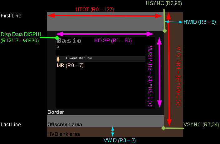
Video Registers
Write the register (R0-R18) you want to set to $FE00, then write the new
value to $FE01
| RegNum | register description | Mode
1 320x256 4 color |
| $FE20 | Screen mode | $D8 |
| R0 | Horizontal total | $7F |
| R1 | Horizontal displayed characters | $50 |
| R2 | Horizontal sync position | $62 |
| R3 | Horizontal sync width/Vertical sync time | $28 |
| R4 | Vertical total | $26 |
| R5 | Vertical total adjust | $00 |
| R6 | Vertical displayed characters | $19 |
| R7 | Vertical sync position | $22 |
| R8 | Interlace/Display delay/Cursor delay | $01 |
| R9 | Scan lines per character | $30 |
| R10 | Cursor start line and blink type | $00 |
| R11 | Cursor end line | $08 |
| R12 | Screen start address H (Address /8) | $30 |
| R13 | Screen start address L (Address /8) | |
| R14 | Cursor position H | |
| R15 | Cursor position L | |
| R16 | Light pen position | |
| R17 | Light pen position | |
| R18 | Cursor width (BBFW) |
Physical Colors
the way Screen Bytes map to visible colors is strangely configurable, they are defined by the "Video ULA palette"... which maps nibbles to colors... if we map colors wrong, the same byte may appear a different color depending if it's on odd or even vertical strips| Color Num | EOR | Color |
| 0 | 7 | Black |
| 1 | 6 | Red |
| 2 | 5 | Green |
| 3 | 4 | Yellow |
| 4 | 3 | Blue |
| 5 | 2 | Magenta |
| 6 | 1 | Cyan |
| 7 | 0 | White |
Hardware Addresses
| Address | Section | Purpose | Details |
| $FE00 | 6845 CRTC Video controller | CRTC Reg Select | Select Register |
| $FE01 | 6845 CRTC Video controller | CRTC Reg Data | Change Register |
| $FE08 | 6850 ACIA Serial controller | Control Register / Status Register | |
| $FE09 | 6850 ACIA Serial controller | Transmit data / Receive Data | |
| $FE10 | Serial ULA Serial system chip | Control Register | |
| $FE20 | Video ULA Video system chip | Video ULA Control | Select Screen Settings |
| $FE20 | Video ULA Video system chip | ULA Palette | %LLLLAAAA L=Logical A=Actual color |
| $FE30 | 74LS161 Paged ROM selector | 4 bit Rom select | %----RRRR |
| $FE40 | 6522 System VIA | Output B / Input B | Sound & Keyboard |
| $FE41 | 6522 System VIA | Output A / Input A | |
| $FE42 | 6522 System VIA | Data Direction B | |
| $FE43 | 6522 System VIA | Data Direction A | |
| $FE44 | 6522 System VIA | T1 Low order Latches/Counter | |
| $FE45 | 6522 System VIA | T1 High order Counter | |
| $FE46 | 6522 System VIA | T1 Low order Latches | |
| $FE47 | 6522 System VIA | T1 High order Latches | |
| $FE48 | 6522 System VIA | T2 Low order Latches/Counter | |
| $FE49 | 6522 System VIA | T2 High order Counter | |
| $FE4A | 6522 System VIA | Shift Register | |
| $FE4B | 6522 System VIA | Auxiliary Control Register | |
| $FE4C | 6522 System VIA | Peripheral Control Register | |
| $FE4D | 6522 System VIA | Interrupt Flags %v12ALSBK | V=systemVia
1=Timer1 (100hz) 2=Timer2 (speech) A=Analog conv L=Lightpen
S=Shift reg B=Vblank K=Keypress |
| $FE4E | 6522 System VIA | Interrupt Enable | |
| $FE4F | 6522 System VIA | Output A / Input A - No Handshake | |
| $FE60 | 6522 User VIA | Output B / Input B | |
| $FE61 | 6522 User VIA | Output A / Input A | |
| $FE62 | 6522 User VIA | Data Direction B | |
| $FE63 | 6522 User VIA | Data Direction A | |
| $FE64 | 6522 User VIA | T1 Low order Latches/Counter | |
| $FE65 | 6522 User VIA | T1 High order Counter | |
| $FE66 | 6522 User VIA | T1 Low order Latches | |
| $FE67 | 6522 User VIA | T1 High order Latches | |
| $FE68 | 6522 User VIA | T2 Low order Latches/Counter | |
| $FE69 | 6522 User VIA | T2 High order Counter | |
| $FE6A | 6522 User VIA | Shift Register | |
| $FE6B | 6522 User VIA | Auxiliary Control Register | |
| $FE6C | 6522 User VIA | Peripheral Control Register | |
| $FE6D | 6522 User VIA | Interrupt Flags | |
| $FE6E | 6522 User VIA | Interrupt Enable | |
| $FE6F | 6522 User VIA | Output A / Input A - No Handshake | |
| $FE80 | 8271 FDC
Floppy disc |
Status Register / Command Register | |
| $FE81 | 8271 FDC
Floppy disc |
Result Register / Parameter Register | |
| $FE82 | 8271 FDC
Floppy disc |
Reset Register | |
| $FE83 | 8271 FDC
Floppy disc |
unused | |
| $FE84 | 8271 FDC
Floppy disc |
Read Data / Write Data | |
| $FEA0 | 68B54 ADLC
ECONET |
Control Reg 1 / Status Reg 1 | |
| $FEA1 | 68B54 ADLC
ECONET |
Control Reg 2,3 / Status Reg 2 | |
| $FEA2 | 68B54 ADLC
ECONET |
Transmit FIFO (frame continue) / Receive FIFO | |
| $FEA3 | 68B54 ADLC
ECONET |
Transmit FIFO (frame terminate) / Receive FIFO | |
| $FEC0 | uPD7002 ADC |
Data latch and conversion start / Status Register | |
| $FEC1 | uPD7002 ADC | High Data Byte | |
| $FEC2 | uPD7002 ADC | Low Data Byte | |
| $FEE0 | Tube ULA |
$FEE0- $FEFF |
Sound Controller - SN76489
The Sound Chip shares a port with the keybord... Before we can send any data to the sound chip, we have to set the port to WRITE... we do this by writing 255 to address $FE43 (we only do this once)We've covered the sound chip in the Z80 tutorials here
Once we've done that, we can write our data to $FE41 in the format below
| Bits | |||||||||
| Command | Bit Details | 7 | 6 | 5 | 4 | 3 | 2 | 1 | 0 |
| Format Template | L=Latch C=Channel T=Type XXXX=Data | L | C | C | T | D | D | D | D |
| Tone - Command 1/2 | C=Channel L=tone Low data | 1 | C | C | 0 | L | L | L | L |
| Tone - Command 2/2 | H= High tone data (Higher numbers = lower tone) | 0 | - | H | H | H | H | H | H |
| Volume | C=Channel (0-2) V=Volume (15=silent 0=max) | 1 | C | C | 1 | V | V | V | V |
| Noise Channel | (Channel 3) M=Noise mode (1=white) R=Rate (3=use tone 2) | 1 | 1 | 1 | 0 | - | M | R | R |
Sheila ADC - Analog to Digital Converter (Joystick)
The Joystick is analog on the BBC... we need to read UD and LR, which will return a value from 0-255....
When it comes to reading the Fire, we use $FE40 - part of the sound/keyboard controller!
| Port | R/W | Purpose | Bits | Details | |
| $FEC0 | W | Data Latch / Conversation Start |
----MFCC | M=Mode (0=8 bit 1=10 bit)... F=Flag (usually 0)... CC=Channel (0/1 = joy1 2/3=joy2) | |
| $FEC0 | R | Status | CBMMm-CC | C=Conversation complete (1=no)...B=busy... M=top two bits of conversiation... m=mode (8/10 bit)... CC=Channel | |
| $FEC1 | R | High Data byte | DDDDDDDD | 8 Bit Data | |
| $FEC2 | R | Low Data byte | DDDD---- | extra 4 low bits of 10/12 bit data |
System Vectors
| Routine | Vector | |||
| Name | Address | Name | Address | Summary of function |
| USERV | $0200 | Reserved | ||
| BRKV | $0202 | Break vector | ||
| IRQ1V | $0204 | All IRQ vector | ||
| IRQ2V | $0206 | Unrecognized IRQ vector | ||
| CLIV | $0208 | Interpret the command line given | ||
| OSCLI | $FFF7 | � | � | |
| OSBYTE | $FFF4 | BYTEV | $020A | Perform miscellaneous OS operation using registers to pass parameters |
| OSWORD | $FFF1 | WORDV | $020C | Perform miscellaneous OS operation control block to pass parameters |
| OSWRCH | $FFEE | WRCHV | $020E | Write character (to screen) from A |
| OSNEWL | $FFE7 | � | � | Write LF,CR (&0A,&0D) to screen |
| OSASCI | $FFE3 | � | � | Write a character (to screen) from A plus LF if (A)=&0D |
| OSRDCH | $FFE0 | RDCHV | $0210 | Read character (from keyboard) to A (Interrupts must be on! - CLI) |
| OSFILE | $FFDD | FILEV | $0212 | Load or save a complete file |
| OSARGS | $FFDA | ARGSV | $0214 | Load or save data about a file |
| OSBGET | $FFD7 | BGETV | $0216 | Load a single byte to A from file |
| OSBPUT | $FFD4 | BPUTV | $0218 | Save a single byte to file from A |
| OSGBPB | $FFD1 | GBPBV | $021A | Load or save a block of memory to file |
| OSFIND | $FFCE | FINDV | $021C | Open or close a file |
| OSRDSC | $FFB9 | � | � | Read byte from screen |
| OSWRSC | $FFB3 | � | � | Write byte to screen |
| FSCV | $021E | File system control entry | ||
| EVNTV | $0220 | Event interrupt | ||
| UPTV | $0222 | User print routine | ||
| NETV | $0224 | Used by Econet to take control of the computer. | ||
| VDUV | $0226 | Used by the VDU driver to direct unrecognised VDU 23 and PLOT commands. | ||
| KEYV | $0228 | Used by the operating system for all keyboard access. Enables the use of external keyboards. | ||
| INSV | $022A | Insert into buffer vector. | ||
| REMV | $022C | Remove from buffer vector. | ||
| CNPV | $022E | Count / purge buffer vector | ||
| IND1V | $0230 | Spare vector. | ||
| IND2V | $0232 | Spare vector. | ||
| IND3V | $0234 | Spare vector. | ||
VDU Codes
These are special character sequences that can be sent to the OS Print
Character routine (OSASCI - $FFE3)
Some take multiple additional byte parameters (+Bytes).
| Dec |
Hex |
CTRL |
+bytes | Function |
| 0 | 0 | � | 0 | Does nothing |
| 1 | 1 | A | 1 | Send next character to printer only |
| 2 | 2 | B | 0 | Enable printer |
| 3 | 3 | C | 0 | Disable printer |
| 4 | 4 | D | 0 | Write text at text cursor |
| 5 | 5 | E | 0 | Write text at graphics cursor |
| 6 | 6 | F | 0 | Enable VDU drivers |
| 7 | 7 | C | 0 | Make a short bleep (BEL) |
| 8 | 8 | H | 0 | Move cursor back one character |
| 9 | 9 | I | 0 | Move cursor forward one character |
| 10 | A | J | 0 | Move cursor down one line |
| 11 | B | K | 0 | Move cursor up one line |
| 12 | C | L | 0 | Clear text area |
| 13 | D | M | 0 | Carriage return |
| 14 | E | N | 0 | Paged mode on |
| 15 | F | O | 0 | Paged mode off |
| 16 | 10 | P | 0 | Clear graphics area |
| 17 | 11 | Q | 1 | Define text colour |
| 18 | 12 | R | 2 | Define graphics colour |
| 19 | 13 | S | 5 | Define logical colour |
| 20 | 14 | T | 0 | Restore default logical colours |
| 21 | 15 | U | 0 | Disable VDU drivers or delete current line |
| 22 | 16 | V | 1 | Select screen MODE |
| 23 | 17 | W | 9 | Re-program display character |
| 24 | 18 | X | 8 | Define graphics window |
| 25 | 19 | Y | 5 | PLOT K,X,Y |
| 26 | 1A | Z | 0 | Restore default windows |
| 27 | 1B | [ | 0 | ESCAPE value |
| 28 | 1C | \ | 4 | Define text window |
| 29 | 1D | ] | 4 | Define graphics origin |
| 30 | 1E | * | 0 | Home text cursor to top left of window |
| 31 | 1F | _ | 2 | Move text cursor to X,Y |
| 127 | 7F | DEL | 0 | Backspace and delete |
OSBYTEs
A=Routine Number... X,Y=Parameters
The OSBYTE Call address is $FFF4 - it is Indirected through $020A
| Dec |
Hex |
Purpose |
| 0 | 0 | Print operating system version |
| 1 | 1 | User OSBYTE call, read |
| 2 | 2 | Select input stream |
| 3 | 3 | Select output stream |
| 4 | 4 | Enable |
| 5 | 5 | Select printer destination |
| 6 | 6 | Set character ignored by printer |
| 7 | 7 | Set RS423 baud rate for receiving data |
| 8 | 8 | Set RS423 baud rate for data transmission |
| 9 | 9 | Set flashing colour mark state duration |
| 10 | A | Set flashing colour space state duration |
| 11 | B | Set keyboard auto-repeat delay interval |
| 12 | C | Set keyboard auto-repeat rate |
| 13 | D | Disable events |
| 14 | E | Enable events |
| 15 | F | Flush selected buffer class |
| 16 | 10 | Select ADC channels to be sampled |
| 17 | 11 | Force an ADC conversion |
| 18 | 12 | Reset soft keys |
| 19 | 13 | Wait for vertical sync |
| 20 | 14 | Explode soft character RAM allocation |
| 21 | 15 | Flush specific buffer |
| 117 | 75 | Read VDU status |
| 118 | 76 | Reflect keyboard status in LEDs |
| 119 | 77 | Close any SPOOL or EXEC files |
| 120 | 78 | Write current keys pressed information |
| 121 | 79 | Perform keyboard scan |
| 122 | 7A | Perform keyboard scan from 16 (&10) |
| 123 | 7B | Inform OS, printer driver going dormant |
| 124 | 7C | Clear ESCAPE condition |
| 125 | 7D | Set ESCAPE condition |
| 126 | 7E | Acknowledge detection of ESCAPE condition |
| 127 | 7F | Check for EOF on an open file |
| 128 | 80 | Read ADC channel or get buffer status |
| 129 | 81 | Read key with time limit |
| 130 | 82 | Read machine high order address |
| 131 | 83 | Read top of OS RAM address (OSHWM) |
| 132 | 84 | Read bottom of display RAM address (HIMEM) |
| 133 | 85 | Read bottom of display address for a given MODE |
| 134 | 86 | Read text cursor position (POS and VPOS) |
| 135 | 87 | Read character at cursor position |
| 136 | 88 | Perform *CODE |
| 137 | 89 | Perform *MOTOR |
| 138 | 8A | Insert value into buffer |
| 139 | 8B | Perform *OPT |
| 140 | 8C | Perform *TAPE |
| 141 | 8D | Perform *ROM |
| 142 | 8E | Enter language ROM |
| 143 | 8F | Issue paged ROM service request |
| 144 | 90 | Perform *TV |
| 145 | 91 | Get character from buffer |
| 146 | 92 | Read from FRED, 1 MHz bus |
| 147 | 93 | Write to FRED, 1 MHz bus |
| 148 | 94 | Read from JIM, 1 MHz bus |
| 149 | 95 | Write to JIM, 1 MHz bus |
| 150 | 96 | Read from SHEILA, mapped I/ O |
| 151 | 97 | Write to SHEILA, mapped I/ O |
| 152 | 98 | Examine buffer status |
| 153 | 99 | Insert character into input buffer |
| 154 | 9A | Write to video ULA control register and copy |
| 155 | 9B | Write to video ULA palette register and copy |
| 156 | 9C | Read/ write 6850 control register and copy |
| 157 | 9D | Fast Tube BPUT |
| 158 | 9E | Read from speech processor |
| 159 | 9F | Write to speech processor |
| 160 | A0 | Read VDU variable value |
| 166 | A6 | Read start address of OS variables (low byte) |
| 167 | A7 | Read start address of OS variables (high byte) |
| 168 | A8 | Read address of ROM pointer table (low byte) |
| 169 | A9 | Read address of ROM pointer table (high byte) |
| 170 | AA | Read address of ROM information table (low byte) |
| 171 | AB | Read address of ROM information table (high byte) |
| 172 | AC | Read address of key translation table (low byte) |
| 173 | AD | Read address of key translation table (high byte) |
| 174 | AE | Read start address of OS VDU variables (low byte) |
| 175 | AF | Read start address of OS VDU variables (high byte) |
| 176 | B0 | Read/ write CFS timeout counter |
| 177 | B1 | Read/ write input source |
| 178 | B2 | Read/ write keyboard semaphore |
| 179 | B3 | Read/ write primary OSHWM |
| 180 | B4 | Read/ write current OSHWM |
| 181 | B5 | Read/ write RS423 mode |
| 182 | B6 | Read character definition explosion state |
| 183 | B7 | Read/ write cassette/ ROM filing system switch |
| 184 | B8 | Read RAM copy of video ULA control register |
| 185 | B9 | Read RAM copy of video ULA palette register |
| 186 | BA | Read/ write ROM number active at last BRK (error) |
| 187 | BB | Read/ write number of ROM socket containing BASIC |
| 188 | BC | Read current ADC channel |
| 189 | BD | Read/ write maximum ADC channel number |
| 190 | BE | Read ADC conversion type |
| 191 | BF | Read/ write RS423 use flag |
| 192 | C0 | Read RS423 control flag |
| 193 | C1 | Read/ write flash counter |
| 194 | C2 | Read/ write mark period count |
| 195 | C3 | Read/ write space period count |
| 196 | C4 | Read/ write keyboard auto-repeat delay |
| 197 | C5 | Read/ write keyboard auto-repeat period |
| 198 | C6 | Read/ write *EXEC file handle |
| 199 | C7 | Read/ write *SPOOL file handle |
| 200 | C8 | Read/ write ESCAPE, BREAK effect |
| 201 | C9 | Read/ write Econet keyboard disable |
| 202 | CA | Read/ write keyboard status byte |
| 203 | CB | Read/ write RS423 handshake extent |
| 204 | CC | Read/ write RS423 input suppression flag |
| 205 | CD | Read/ write cassette/ RS423 selection flag |
| 206 | CE | Read/ write Econet OS call interception status |
| 207 | CF | Read/ write Econet OSRDCH interception status |
| 208 | D0 | Read/ write Econet OSWRCH interception status |
| 209 | Dl | Read/ write speech suppression status |
| 210 | D2 | Read/ write sound suppression status |
| 211 | D3 | Read/ write BELL channel |
| 212 | D4 | Read/ write BELL envelope number/ amplitude |
| 213 | D5 | Read/ write BELL frequency |
| 214 | D6 | Read/ write BELL duration |
| 215 | D7 | Read/ write startup message and !BOOT options |
| 216 | D8 | Read/ write length of soft key string |
| 217 | D9 | Read/ write number of lines printed since last page |
| 218 | DA | Read/ write number of items in VDU queue |
| 219 | DB | Read/ write TAB character value |
| 220 | DC | Read/ write ESCAPE character value |
| 221 | DD | Read/ write character &CO to &CF status |
| 222 | DE | Read/ write character &DO to &DF status |
| 223 | DF | Read/ write character &EO to &EF status |
| 224 | E0 | Read/ write character &FO to &FF status |
| 225 | El | Read/ write function key status |
| 226 | E2 | Read/ write SHIFT+ function key status |
| 227 | E3 | Read/ write CTRL+function key status |
| 228 | E4 | Read/ write CTRL+SHIFT+function key status |
| 229 | E5 | Read/ write ESCAPE key status |
| 230 | E6 | Read/ write flags determining ESCAPE effects |
| 231 | E7 | Read/ write JRQ bit mask for user 6522 |
| 232 | E8 | Read/ write IRQ bit mask for 6850 |
| 233 | E9 | Read/ write IRQ bit mask for system 6S22 |
| 234 | EA | Read flag indicating Tube presence |
| 235 | EB | Read flag indicating speech processor presence |
| 236 | EC | Read/ write write character destination status |
| 237 | ED | Read/ write cursor editing status |
| 238 | EE | Read/ write location &27E, not used by 05 1.20 |
| 239 | EF | Read/ write location &27F, not used by 05 1.20 |
| 240 | F0 | Read/ write location &280, not used by 05 1.20 |
| 241 | F1 | Read/ write location &281, used by *FX 1 |
| 242 | F2 | Read RAM copy of serial processor ULA |
| 243 | F3 | Read/ write timer switch state |
| 244 | F4 | Read/ write soft key consistency flag |
| 245 | F5 | Read/ write printer destination flag |
| 246 | F6 | Read/ write character ignored by printer |
| 247 | F7 | Read/ write first byte of BREAK intercept code |
| 248 | F8 | Read/ write second byte of BREAK intercept code |
| 249 | F9 | Read/ write third byte of BREAK intercept code |
| 250 | FA | Read/ write location &28A, not used by OS1.20 |
| 251 | FB | Read/ write location &28B, not used by OS1.20 |
| 252 | FC | Read/ write current language ROM number |
| 253 | FD | Read/ write last BREAK type |
| 254 | FE | Read/ write available RAM |
| 255 | FF | Read/ write start up options |
Interrupt Vectors
The standard 6502 interrupt vectors from $FFFA+ are ROM, however these jump to vectors in low memory addresses (Jumps to the address at...)
IRQ and BRK interrupts back up A at address $00FC.
NMI is different, it causes a jump to address $0D00 - the firmware puts an RTI command here during reset.
| Vector Address |
Remaps to
|
Function
|
Registers
stored by Firmware |
| $FFFE-$FFFF | Vector
at $0202-$0203 |
BRK | STA $FC |
| $FFFE-$FFFF |
Vector at $0204-$0205 | IRQ1 (Primary
IRQ) |
STA $FC |
| $FFFE-$FFFF | Vector at $0206-$0207 | IRQ2
(Unrecognised IRQ) |
STA $FC |
| $FFFA-$FFFB |
Jumps to $0D00 | NMI |
We need to clear the interrupt, we can do this by writing #255 to $FE4D
;$FE4D Interrupt flag register- %7654321
; 7 = IRQ
; 6 = Timer 1
; 5 = Timer 2
; 4 = CB1 Active Edge
; 3 = CB2 Active Edge
; 2 = Shift Reg complete 8 shifts
; 1 = CA1 Active Edge
; 0 - CA2 Active Edge
Key Reading
| Key reading on the BBC is a little
weird and rather poorly documented Essentially you have to select a row (0-8) and Column (0-9), then read in the state of each key one bit at a time!.. these are both read and written to port $FE4F
When Written Bits 0-3 (Marked C) select the Column (0-9) and bits 4-6 (Marked R) select the Row (0-8)... Bit 7 has no purpose When Read Bit 7 returns the Keystate and bits 6-0 have no purpose An example working piece of code is shown to the right, it's partially based on the disassemblies of the firmware. You will need a PrintHex command to show the read byte to screen. |
LDA #$7F
;set port A for input on bit 7 others outputs STA $FE43 LDA #$03 ;stop auto scan STA $FE40 ; This section may not be needed ;LDA #$0F ;select non-existent keyboard column F (0-9 only!) ;STA $FE4F ; ;LDA #$01 ;cancel keyboard interrupt ;STA $FE4D ; ldy #0 KeyNextLine: ldx #8 tya KeyNextBit: pha sta $FE4F lda $FE4F rol pla rol z_as clc adc #%00010000 dex bne KeyNextBit lda z_as iny sta (z_hl),y jsr PrintHex tya cmp #8 bne KeyNextLine LDA #$0B ;select auto scan of keyboard STA $FE40 ;tell VIA |
| View Options |
| Default Dark |
| Simple (Hide this menu) |
| Print Mode (white background) |
| Top Menu |
| ***Main Menu*** |
| Youtube channel |
| Patreon |
| Introduction to Assembly (Basics for absolute beginners) |
| Amazon Affiliate Link |
| Forum |
| AkuSprite Editor |
| ChibiTracker |
| Dec/Bin/Hex/Oct/Ascii Table |
| Alt Tech |
| Archive.org |
| Bitchute |
| Odysee |
| Rumble |
| DailyMotion |
| Please note: I wlll upload more content to these alt platforms based on the views they bring in |
| 68000 Content |
| ***68000 Tutorial List*** |
Learn 68000 Assembly  |
| Hello World Series |
| Platform Specific Series |
| Simple Samples |
| Grime 68000 |
| 68000 Downloads |
| 68000 Cheatsheet |
| Sources.7z |
| DevTools kit |
| 68000 Platforms |
| Amiga 500 |
| Atari ST |
| Neo Geo |
| Sega Genesis / Mega Drive |
| Sinclair QL |
| X68000 (Sharp x68k) |
| 8086 Content |
| Learn 8086 Assembly |
| Platform Specific Series |
| Hello World Series |
| Simple Samples |
| 8086 Downloads |
| 8086 Cheatsheet |
| Sources.7z |
| DevTools kit |
| 8086 Platforms |
| Wonderswan |
| MsDos |
| ARM Content |
| Learn ARM Assembly |
| Learn ARM Thumb Assembly |
| Platform Specific Series |
| Hello World |
| Simple Samples |
| ARM Downloads |
| ARM Cheatsheet |
| Sources.7z |
| DevTools kit |
| ARM Platforms |
| Gameboy Advance |
| Nintendo DS |
| Risc Os |
| Risc-V Content |
| Learn Risc-V Assembly |
| Risc-V Downloads |
| Risc-V Cheatsheet |
| Sources.7z |
| DevTools kit |
| MIPS Content |
| Learn Risc-V Assembly |
| Platform Specific Series |
| Hello World |
| Simple Samples |
| MIPS Downloads |
| MIPS Cheatsheet |
| Sources.7z |
| DevTools kit |
| MIPS Platforms |
| Playstation |
| N64 |
| PDP-11 Content |
| Learn PDP-11 Assembly |
| Platform Specific Series |
| Simple Samples |
| PDP-11 Downloads |
| PDP-11 Cheatsheet |
| Sources.7z |
| DevTools kit |
| PDP-11 Platforms |
| PDP-11 |
| UKNC |
| TMS9900 Content |
| Learn TMS9900 Assembly |
| Platform Specific Series |
| Hello World |
| TMS9900 Downloads |
| TMS9900 Cheatsheet |
| Sources.7z |
| DevTools kit |
| TMS9900 Platforms |
| Ti 99 |
| 6809 Content |
| Learn 6809 Assembly |
| Learn 6309 Assembly |
| Platform Specific Series |
| Hello World Series |
| Simple Samples |
| 6809 Downloads |
| 6809/6309 Cheatsheet |
| Sources.7z |
| DevTools kit |
| 6809 Platforms |
| Dragon 32/Tandy Coco |
| Fujitsu FM7 |
| TRS-80 Coco 3 |
| Vectrex |
| 65816 Content |
| Learn 65816 Assembly |
| Hello World |
| Simple Samples |
| 65816 Downloads |
| 65816 Cheatsheet |
| Sources.7z |
| DevTools kit |
| 65816 Platforms |
| SNES |
| eZ80 Content |
| Learn eZ80 Assembly |
| Platform Specific Series |
| eZ80 Downloads |
| eZ80 Cheatsheet |
| Sources.7z |
| DevTools kit |
| eZ80 Platforms |
| Ti84 PCE |
| IBM370 Content |
| Learn IBM370 Assembly |
| Simple Samples |
| IBM370 Downloads |
| IBM370 Cheatsheet |
| Sources.7z |
| DevTools kit |
| Super-H Content |
| Learn SH2 Assembly |
| Hello World Series |
| Simple Samples |
| SH2 Downloads |
| SH2 Cheatsheet |
| Sources.7z |
| DevTools kit |
| SH2 Platforms |
| 32x |
| Saturn |
| PowerPC Content |
| Learn PowerPC Assembly |
| Hello World Series |
| Simple Samples |
| PowerPC Downloads |
| PowerPC Cheatsheet |
| Sources.7z |
| DevTools kit |
| PowerPC Platforms |
| Gamecube |
| Work in Progress |
| ChibiAndroids |
| Misc bits |
| Ruby programming |
Buy my Assembly programming book
on Amazon in Print or Kindle!


Available worldwide!
Search 'ChibiAkumas' on
your local Amazon website!
Click here for more info!


Buy my Assembly programming book
on Amazon in Print or Kindle!
Available worldwide!
Search 'ChibiAkumas' on
your local Amazon website!
Click here for more info!
Buy my Assembly programming book
on Amazon in Print or Kindle!
Available worldwide!
Search 'ChibiAkumas' on
your local Amazon website!
Click here for more info!