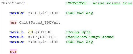
Common Data format for Joypad controls used by these tutorials
| On the Z80 We used to read in the buttons and fires into a
single byte... on the 68000 systems we're going to keep the
same format for ULDR Fire1+2 and start... but we'll also
extend into a second byte for any extra fire buttons we
have... for each bit, a 1 means the button is up (unpressed) a 0 means the button is down (pressed) We'll load player 1's joystick data into D0... and player 2's into D1 |
|
||||||||||||||||||||||||||||||||||||
| Our test program is very simple, all it does is read in the two controllers, and show the value of the registers to the screen. | 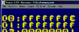 |
Genesis Joystick Ports
Each joystick has two ports - on for Reading or Writing of Data... and one Control port, to set the direction (Read or Write) of each bit of the data port (0=Read, 1=Write)
We will need to set bit 6 to Write to read all the Genesis Buttons
| End address | Description |
| $A10003 | Controller 1 data |
| $A10005 | Controller 2 data |
| $A10009 | Controller 1 control |
| $A1000B | Controller 2 control |
The Genesis Joystick ports are backwards compatible with the Mastersystem, therefore we have to send a sequence of 1's and 0's to the 'TH' bit (Bit 6) to select the different buttons available
Note: Some of the buttons are duplicated in multiple read configurations.
| TH Bit Write | 7 | 6 | 5 | 4 | 3 | 2 | 1 | 0 | Notes |
| 1 | 0 | (TH) | C | B | Right | Left | Down | Up | |
| 0 | 0 | (TH) | Start | A | 0 | 0 | Down | Up | |
| 1,0,1,0,1*,0 | 0 | (TH) | C | B | X | Y | Z | Mode | * should perform a write of 0 to TH afterwards to reset sequence (1,0,1,0,1,0) |
 |
If you
only want to use the basic 3 fires, you can ignore the 3rd
option... also note that not all 6 button joysticks have a
'Mode' button. |
Getting Data from the Joysticks
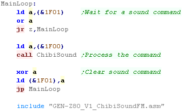
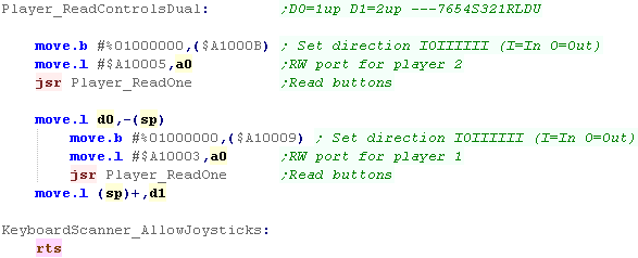
| We're going to process Joystick
2, then Joystick 1, using a common function to do the reading
and bitshifting work (Player_ReadOne) Whichever Joystick we want to read from, we need to first set all the bits to Read EXCEPT bit 6 - which we need to set to Write ,0We then move the data port to use into A0 (as it's different for each joystick) before calling Player_ReadOne |
 |
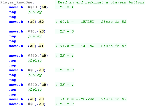
| We need to send commands to the
data port, alternating bit 6 between 1,0,1,0,1,0... we
do to NOP commands to effect a short delay to allow the
joystick hardware to respond to the change. After the 1st,3rd and 5th flip, we need to store a byte, we back these up intoo D1,D2 and D3... we'll use these in a moment. |
 |
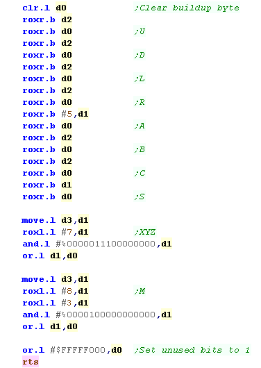
| The bits in D1, D2 and D3 are
in the wrong order, so we're going to do a series of bit
shifts and masks to get the buttons into our 'standard format' We need to get the bit for A and Start into the CBRLDU bits, and M and XYZ are in the wrong order - we want M as the last button |
 |

Mouse Joystick position ports
joysticks on the Amiga connect to the Mouse ports... the data is 'encoded' in the bits of the Horizontal Data
| NAME | ADDR | FUNCTION |
| JOY0DAT | $DFF00A | Joystick-mouse 0 data (vert,horiz) |
| JOY1DAT | $DFF00C | Joystick-mouse 1 data (vert,horiz) |
To covert data from these ports into a traditional digital joystick direction, we need to do some logical operations.
| Direction | Represented
by Bits in $DFF0A/C |
| Right | 1 |
| Left | 9 |
| Down | 1 XOR 0 |
| UP | 9 XOR 8 |
We also need to get the joystick fire buttons from a different port:
| Address | Purpose |
| $BFE001 | FIR1 / FIR0 / RDY / TK0 / WPRO / CHNG / LED / OVL |
| $BFE201 | Direction for bits of port A ($BFE001)... 1=Out / 0=In |
 |
The Amiga
uses the same ports for Mice and Joysticks... we'll assume
Port 0 has a Mouse, and Port 1 has a Joystick... While our code will support 2 joysticks, Port 1's joystick will be Joystick 1, and Port 0's will be Joystick 2. |
Common Data format for Joypad controls used by these tutorials
| On the Z80 We used to read in the buttons and fires into a
single byte... on the 68000 systems we're going to keep the
same format for ULDR Fire1+2 and start... but we'll also
extend into a second byte for any extra fire buttons we
have... for each bit, a 1 means the button is up (unpressed) a 0 means the button is down (pressed) We'll load player 1's joystick data into D0... and player 2's into D1 |
|
||||||||||||||||||||||||||||||||||||
| Our test program is very simple, all it does is read in the two controllers, and show the value of the registers to the screen. | 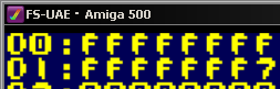 |
Reading the Joysticks
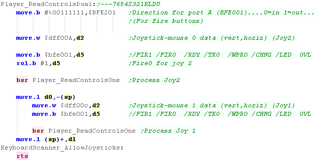
| We're going to need to set the
top two bits of Port A ($BFE001) to READ so we can get the
joystick buttons, Next we'll read joystick 2's XY data from $DFF00A, (we're treating Mouse Port 0 as Joystick 2)... we'll load this into D2. We're also going to load Joystick 2's fire button from $BFE001 into D5... it's in Bit 6, but we need it in bit 7 We're going to call Player_ReadControlsOne to covert the input into the correct format in D0... Once we've done Joystick 2, we push the result onto the stack, and do the same for Joystick 1 |
 |
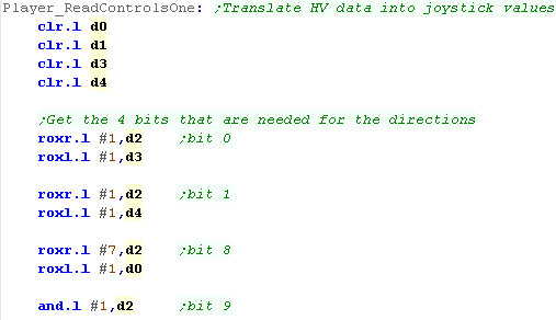
| First we're going to get the 4
bits we need from the Mouse position word into 4 registers
(0,1,8 and 9) We'll need these to calculate the U D L R position of the joystick in a moment. |
 |
| We use the bits we extracted in the last stage to calculate the state of the Up and Down directions, and we shift all the bits into our destination register D0 | 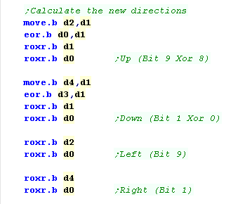 |
| Finally we want to shift in the Fire bit into Bit 4, we then need to flip all the bits of UDLR, and set all the unused bits to 1. | 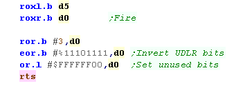 |
| Because there will often be a Mouse plugged into Port 0, Joystick 2 may give unpredictable results, so you should either ignore it, or keep it disabled by default. |  |
Palette Definitions on the x68000
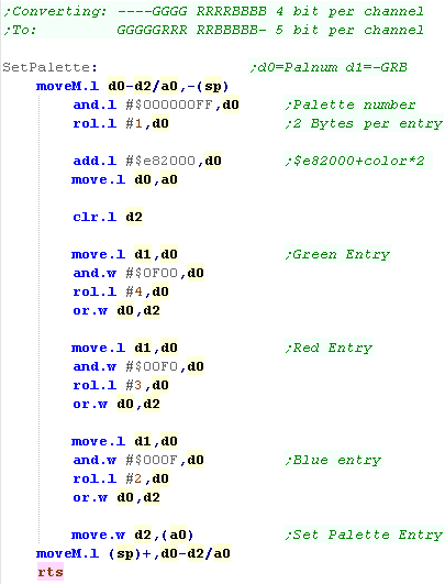
| The Palette on the x68000 use 2
bytes per entry... it uses 5 bits per channel. In our tutorials we use a common palette format, |
|
||||||||||||||||||||||||||||||||||||||||||||||||||||||
| We use Memory addresses
$E82000-$E82220 to define the palettes of the x68000, Each entry uses 2 bytes, and we have different definitions for the Graphics layers, Text layers, and Sprites |
|
Setting the palette
| We define our palette with two
bytes per entry Our code will convert this for every system (Except the QL which has a fixed 8 color palette) |
 |
| We're going to use these
definitions with our 'SetPalette' function that will set each
color for us... We just need to loop around all the colors we need. We'll look at SetPalette next... |
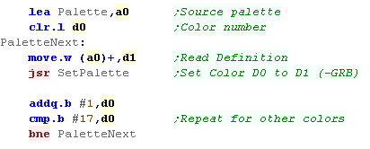 |
| We need to split up each of our
3 channels, and move them around. Although in the correct GRB order, our definitions are 4 bits per pixel, and the x68000's are 5 bits, we need to shift them around. We also need to calculate the address of the palette we want to change, The palette entries for the background start from $E82000, the sprite palettes start from $E82220 |
 |
| Note that we do not use the 'Text layer' for
our text in these tutorials, we draw directly to the bitmap
layer, so we don't set the text palette here. We WILL be looking at sprites in a later tutorial! |
 |
 |
Lesson
P14 - Palette definitions on
the Atari ST While later versions may have had better color, the basic Atari uses 3 bits per channel, Lets learn how to set the colors with our palette |
 |
 |
|
 |
Palette Definitions on the Atari ST
| The Palette on the Atari ST use
2 bytes per entry... it uses 3 bits per channel. In our tutorials we use a common palette format which uses one nibble per channel We use Memory addresses $FF8240-$FF825F to define the palettes of the Atari ST, Each entry uses 2 bytes |
|
Setting the palette
| We define our palette with two
bytes per entry Our code will convert this for every system (Except the QL which has a fixed 8 color palette) |
|
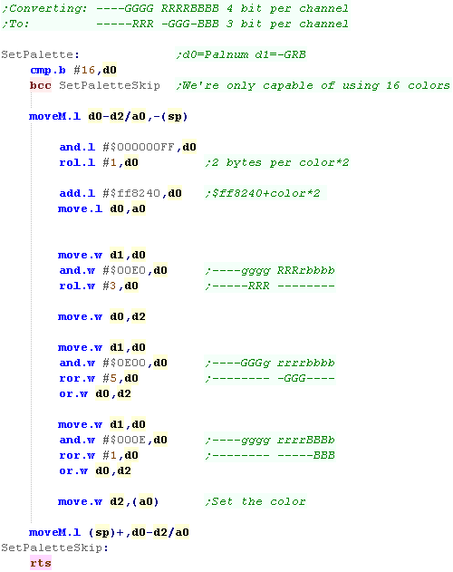
| We're going to use these
definitions with our 'SetPalette' function that will set each
color for us... We just need to loop around all the colors we need. We'll look at SetPalette next... |
|
| We need to split up each of our
3 channels, and move them around. Although in the correct GRB order, our definitions are 4 bits per pixel, and the Atari's are 3 bits, we also need to shift them around. We AND with $E (%1110 ) to keep the 3 bits we want and use ROL to shift those bits in the correct position We also need to calculate the address of the palette we want to change, The palette entries start from $ff8240, and each uses 2 bytes, so we do a ROL to double the palette number to get the byte offset |
 |
 |
The
Atari ST has no Hardware sprites or other layers, so these
16 palette entries are all that the basic Atari ST has... The Falcon had more colors, but it's outside of the scope of these tutorials. |
 |
Lesson
P15 - Palette Definitions on
the NeoGeo The NeoGeo uses 5 bits per channel, has 16 colors per palette, and up to 256 palettes! Lets learn how to set the colors on the Neo Geo! |
|
|
|
Color definitions
Palette data is stored between $400000-$401FFF
Each color is 2 bytes in size, there are 16 colors in each palette, and 256 palettes.
The first color in the first palette is special ($400000), it must be $8000... this is called the "Reference color"
The last color in the last palette is special ($401FFE), it is the "Background" color that shows through, when all other layers are transparent
By default, the 'offscreen' border areas of the tilemap are filled with Color $400004
The 16 bits of Color data are in the following format:
| F | E | D | C | B | A | 9 | 8 | 7 | 6 | 5 | 4 | 3 | 2 | 1 | 0 | |
| D | R0 | G0 | B0 | R4 | R3 | R2 | R1 | G4 | G3 | G2 | G1 | B4 | B3 | B2 | B1 |
The Color format is quite odd!
Each color is defined by 5 bits.. .but the lowest bits for each channel is separate from the rest... this means each color can be quickly defined by a single nibble - or all 5 can be used together...
There is also a "Dark" bit... which is effectively the least significant bit for all 3 color channels.
|
The 'Dark
bit' allows an easy way to make all the colors darker, and is
probably most useful to effect a 'pause' option... In these tutorials we use a common format of 4 bits per channel, so we won't use R0,G0 or B0 in these examples. |
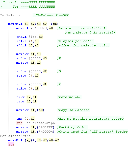
Setting the palette
| We define our palette with two
bytes per entry Our code will convert this for every system (Except the QL which has a fixed 8 color palette) |
|
| We're going to use these
definitions with our 'SetPalette' function that will set each
color for us... We just need to loop around all the colors we need. We'll look at SetPalette next... |
|
| On the NeoGeo we could use
5 bits per channel, but our definition only has 4. We'll split each of the channels around, and move them using ROR and ROL... When it comes to the palettes, palette ram starts at $400000 with Palette 0... Palette 0 has some special colors, so we'll start using Palette 1 instead - which starts at $400020... Each entry is two bytes, so we double the color number with a ROL Once we've set the main color, we're going to do a check to see if we're setting color 0... If we are, we want to set the common background color at $401FFE.... We're also going to set the 'border color' which uses color 2 of palette 0 at $400004 |
 |
Color Ram addresses
Setting colors on the Genesis is the same as writing to memory... we set the VDP Write address to C0xx0000 - where xx is the byte of the color entry.
Setting colors on the Genesis is the same as writing to memory... we set the VDP Write address to C0xx0000 - where xx is the byte of the color entry.
| Palette | ColorNum | Address | Palette | ColorNum | Address | Palette | ColorNum | Address | Palette | ColorNum | Address |
| Palette 0 | Color 0 | $C0000000 | Palette 1 | Color 0 | $C0200000 | Palette 2 | Color 0 | $C0400000 | Palette 3 | Color 0 | $C0600000 |
| Color 1 | $C0020000 | Color 1 | $C0220000 | Color 1 | $C0420000 | Color 1 | $C0620000 | ||||
| Color 2 | $C0040000 | Color 2 | $C0240000 | Color 2 | $C0440000 | Color 2 | $C0640000 | ||||
| Color 3 | $C0060000 | Color 3 | $C0260000 | Color 3 | $C0460000 | Color 3 | $C0660000 | ||||
| Color 4 | $C0080000 | Color 4 | $C0280000 | Color 4 | $C0480000 | Color 4 | $C0680000 | ||||
| Color 5 | $C00A0000 | Color 5 | $C02A0000 | Color 5 | $C04A0000 | Color 5 | $C06A0000 | ||||
| Color 6 | $C00C0000 | Color 6 | $C02C0000 | Color 6 | $C04C0000 | Color 6 | $C06C0000 | ||||
| Color 7 | $C00E0000 | Color 7 | $C02E0000 | Color 7 | $C04E0000 | Color 7 | $C06E0000 | ||||
| Color 8 | $C0100000 | Color 8 | $C0300000 | Color 8 | $C0500000 | Color 8 | $C0700000 | ||||
| Color 9 | $C0120000 | Color 9 | $C0320000 | Color 9 | $C0520000 | Color 9 | $C0720000 | ||||
| Color 10 | $C0140000 | Color 10 | $C0340000 | Color 10 | $C0540000 | Color 10 | $C0740000 | ||||
| Color 11 | $C0160000 | Color 11 | $C0360000 | Color 11 | $C0560000 | Color 11 | $C0760000 | ||||
| Color 12 | $C0180000 | Color 12 | $C0380000 | Color 12 | $C0580000 | Color 12 | $C0780000 | ||||
| Color 13 | $C01A0000 | Color 13 | $C03A0000 | Color 13 | $C05A0000 | Color 13 | $C07A0000 | ||||
| Color 14 | $C01C0000 | Color 14 | $C03C0000 | Color 14 | $C05C0000 | Color 14 | $C07C0000 | ||||
| Color 15 | $C01E0000 | Color 15 | $C03E0000 | Color 15 | $C05E0000 | Color 15 | $C07E0000 |
Colors are defined by 16 bits in the
following format
| F | E | D | C | B | A | 9 | 8 | 7 | 6 | 5 | 4 | 3 | 2 | 1 | 0 | |
| - | - | - | - | B2 | B1 | B0 | - | G2 | G1 | G0 | - | R2 | R1 | R0 | - |
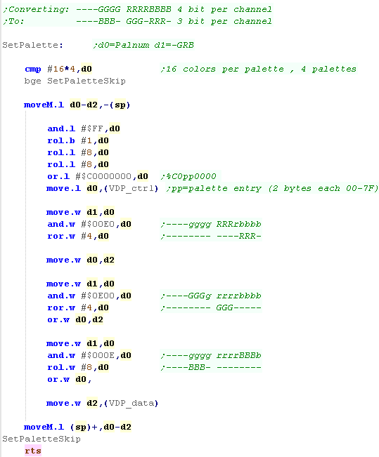
Setting the palette
| We define our palette with two
bytes per entry Our code will convert this for every system (Except the QL which has a fixed 8 color palette) |
|
| We're going to use these
definitions with our 'SetPalette' function that will set each
color for us... We just need to loop around all the colors we need. We'll look at SetPalette next... |
|
| As each color uses 2 bytes, we're
going to have to double the color number, we're also going to
have to move it from $------XX to $C0XX---- to get the correct
destination memory address We write this to the VDP_CTRL port to select the destination for the new color definition We now need to separate the 3 channels, taking 3 bits of each, We AND with $E (%1110 ) to keep the 3 bits we want and use ROL and ROR to shift those bits in the correct position Now we've built up the new color we write it to VDP_DATA |
 |
|
Remember...
While the MasterSystem had the same palette capabilities, the
Gamegear actually had BETTER 4 bit per channel color! It's got to be a rare case of a 16 bit machine being beaten by it's 8 bit predecessor! |
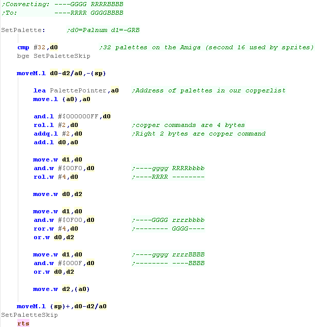
Palette Definitions
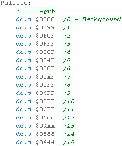
| Palette definitions on the Amiga are performed by writing to
memory registers between $DFF180 and $DFF1BE Definitions can be performed by writing a word to these registers, with 4 bits per channel in the format shown to the right In these tutorials we use a common format of $_GRB... we will need to convert this to $_RGB for the Amiga |
|
|||||||||||||||||||||||||||||||||||||||||||||||||||||||||||||||||||||||||||||||||||||||||||||||||||
| There are a set of 32 words
between $DFF180 and $DFF1BE, We don't actually set these directly, we want to change them within our copperlist! During our Copperlist definition, we've stored the address of the first palette definition, and we use this to alter the entries in the CopperList. As the copperlist applies to the screen every redraw, changing the copperlist will change the visible colors. |
|
| Although we
'can' write directly to the addresses, it's not practical for
the Amiga. Instead we modify the copperlist in Chip Ram, and that does the job |
|
The Color Changing Code
| It's the Copperlist that actually effectively sets the
colors on the Amiga, so the code that actually sets the colors
is in the v1_BitmapMemory.asm... We store the address of the first palette change code in 'PalettePointer' |
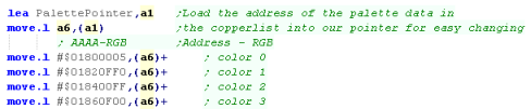 |
| We define our palette with two
bytes per entry Our code will convert this for every system (Except the QL which has a fixed 8 color palette) |
|
| We're going to use these definitions with our 'SetPalette'
function that will set each color for us... We just need to loop around all the colors we need. We'll look at SetPalette next... |
|
| When we want to set the
palette, first we check we're being asked to change a color
less than 31, As our Copperlist entry uses 4 byte entries we rotate our palette number left 2 times to multiply it by 4, We then add 2 - as the left two bytes are the Address (The right 2 are the -RGB palette definition) We now split out each channel from the $-GRB source definition into the $-RGB definition the Amiga needs, Once we've done this we write it to the copperlist address in a0 The color will change during the next screen redraw! |
 |
 |
Lesson
P18 - Sound on
the X68000 The x68000 has a FM sound chip, which we can use to make music, In this tutorial we'll learn how to make simple sounds! |
|
|
|
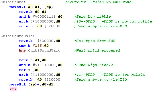
FM Sound on the x68000 with
the YM2151 Chip
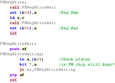
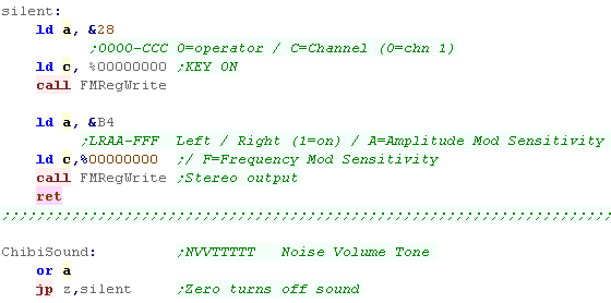
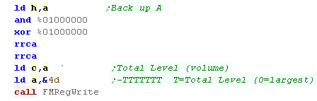
| For full details of the YM2151 can be found in the YM2151
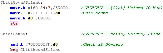
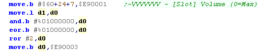
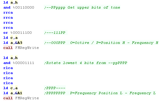
PDF The FM sound chip has 8 channels.... Each channel's sound can be built up with 4 different 'slots'... meaning there are a total of 32 slots... these slots are turned on or off when the sound is triggered Setting a register is easy, we write the register number to $E90001 , then we write the 8 bit value to $E90003 For registers with 32 slots (eg $60 - volume) we can calculate the address of a channels slot with the formula: Address = RegisterBase + 8*ChannelSlot + Channel So if RegisterBase=$60 , ChannelSlot=3 and Channel=7 then we get $60+24+7 |
Setting
a register on the X68000 move.b #$20,$E90001 ;Reg num move.b #%11000000,$E90003 ;New val |
YM2151 Registers
The YM2151 is controlled by 255
registers, that are summarized below:
| Address | 7 | 6 | 5 | 4 | 3 | 2 | 1 | 0 | Summary | Bit Meanings |
| $01 | T | T | T | T | T | T | T | T | Test | T=Test |
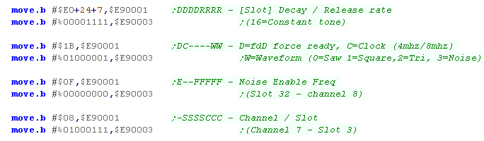
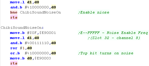
| $08 | - | S | S | S | S | C | C | C | Key On (Play Sound) | C=Channel S=Slot (C2 � M2 � C1 � M1) |
| $0F | E | - | - | F | F | F | F | F | Noise | E=noise
enable F=Frequency (Channel 7) |
| $10 | C | C | C | C | C | C | C | C | CLKA1 | |
| $11 | - | - | - | - | - | - | C | C | CLKA2 | |
| $12 | C | C | C | C | C | C | C | C | CLKB | |
| $14 | C | - | F | F | I | I | L | L | C=CSM F=F-Reset I=IRQEN L=LOAD | |
| $18 | L | L | L | L | L | L | L | L | LFREQ | |
| $19 | M | M | M | M | M | M | M | M | PMD/AMD | |
| $1B | D | C | - | - | - | - | W | W | D=fdD force ready C=Clock (4mhz/8mhz) W=Waveform (0=Saw 1=Square,2=Tri, 3=Noise) | |
| $20-$27 | L | R | F | F | F | C | C | C | Chn0-7� | F=Feedback, C=Connection |
| $28-$2F | - | O | O | O | N | N | N | N | Chn0-7� KeyCode | O=Octive, N=Note |
| $30-$37 | F | F | F | F | F | F | - | - | Chn0-7� Key Fraction | F=Fraction |
| $38-$3F | - | P | P | P | - | A | A | A | Chn0-7� PMS / AMS | P=PMS , A=AMS |
| $40-$5F | - | D | D | D | M | M | M | M | Slot0-31. Decay/Mult | D=Decay D1T, M=Mult |
| $60-$7F | - | V | V | V | V | V | V | V | Slot0-31. Volume | V=Volume
(TL) (0=max) |
| $80-$9F | K | K | - | A | A | A | A | A | Slot0-31. Keyscale / Attack | K=Keycale, A=attack |
| $A0-$BF | A | - | - | D | D | D | D | D | Slot0-31. AMS / Decay | A=AMS-EN, D=Decay D1R |
| $C0-$DF | T | T | - | D | D | D | D | D | Slot0-31. DeTune / Decay | T=Detune DT2, D=Decay D2R |
| $E0-$FF | D | D | D | D | R | R | R | R | Slot0-31. Decay / Release | D=Decay D1L, R=Release Rate |