Your graphics code does not work on real hardware ( which is a sega master system 2).
I was trying to make a game using your code to draw backgrounds and software
sprites for the sega master system 2 but your code does not work when used in
a simple way on real hardware sega master system 2.
I made a simple 32KB cartridge program only using your code-which there is not much of-to draw a 256 square block of tiles (16 tiles high and 16 tiles wide)
see
16by16blockoftiles.png below
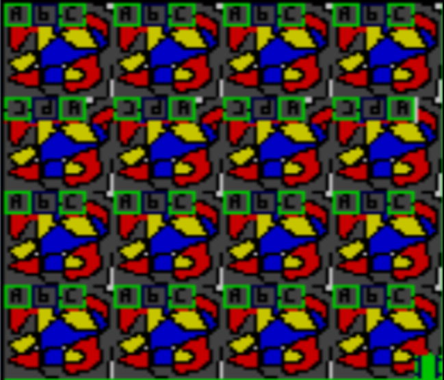
- 16by16blockoftiles.png (92.68 KiB) Viewed 32256 times
in the version 3.64 Fusion emulator it works as expect and showing the square block of tles drawn on screen using your FillAreaWithTiles subroutine code and some of your other subroutines code see
see emulatoroutput.png below
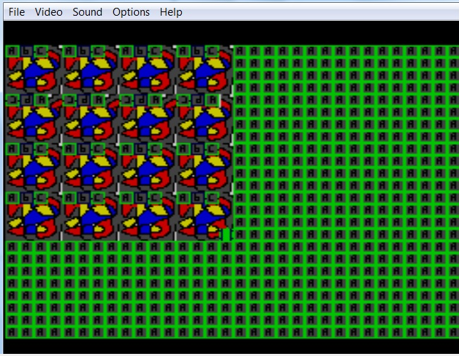
- emulatoroutput.png (167.57 KiB) Viewed 32256 times
But on
a real sega master system 2 it shows as shown in the photo and the photo was taken of the TV screen
realhardwaresegaoutput.jpeg below
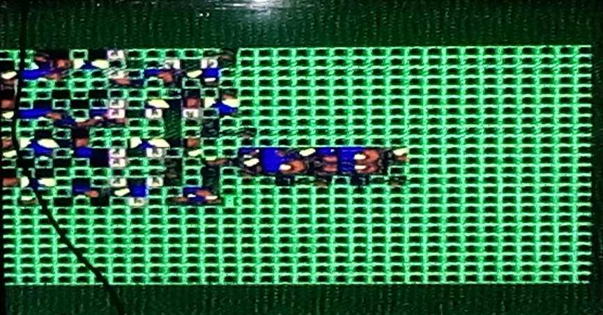
- realhardwaresegaoutput.jpeg (86.34 KiB) Viewed 32256 times
The black line is the aerial of the master system 2 so just ignore that
and the white spot is a flash from the camera so just ingnore that.
Clearly the output is incorrect from your code and has a bug somewhere-
the most obvious different is that is shows a square of 16 by 16 tiles
in the emulator and on real hardware it is NOT a square of 16 by 16 tiles.
Another obvious difference is the output on real hardware looks
less repetitive in the pattern in the 16 by 16 block.
For some reason I could not upload the .RAW 16 by 16 tiles image generated
by akusprite but it would be easy to make a substitute image anyway
The code used from your lessons to make the ROM image used to test both on the real hardware
sega master system 2 and the Fusion sega emulator is given below .
;;;Simple graphics tile drawing code that
;;;;does not work on real hardware (sega master system 2)
vdpControl equ &BF
vdpData equ &BE
org &0000
jr ProgramStart ;&0000 - RST 0
ds 6,&C9 ;&0002 - RST 0
ds 8,&C9 ;&0008 - RST 1
ds 8,&C9 ;&0010 - RST 2
ds 8,&C9 ;&0018 - RST 3
ds 8,&C9 ;&0020 - RST 4
ds 8,&C9 ;&0028 - RST 5
ds 8,&C9 ;&0030 - RST 6
ds 8,&C9 ;&0038 - RST 7
ds 38,&C9 ;&0066 - NMI
ds 26,&C9 ;&0080
; effective Start address &0080
ProgramStart:
di ;Disable interrupts
im 1 ;Interrupt mode 1
ld sp, &dff0 ;Default stack
;init the screen
ld hl,VdpInitData ;Source of data
ld b,VdpInitDataEnd-VdpInitData ;Byte count
ld c,vdpControl ;Destination port
otir ;Out (c),(hl).. inc HL... dec B, djnz
ld hl, &c000 ; set VRAM write address to CRAM (palette) address 0
; note &C0-- is a set palette command... it's not a literal memory address
call prepareVram
ld hl,PaletteData ;Source of data
ld b,32 ;Byte count (16 on SMS)
ld c,vdpData ;Destination port
otir ;Out (c),(hl).. inc HL... dec B, djnz
ld de,0; this defines the tiles using .RAW file it is a 4 by 4 set of tile
ld hl,Bitmap; the tiles data here is shared with the sprites
ld bc,BitmapEnd-Bitmap
call DefineTiles
ld bc,&0000
ld hl,&1010;THIS IS THE tst image 16 by 16 tiles( or 10 by 10 in hex)
ld de,&0000
call FillAreaWithTiles
pausescreenloop:
ld a,0; does nothing useful except pause screen
inc a
jp pausescreenloop
prepareVram: ;Set vdpData to write to memory address HL in vram
ld a,l
out (vdpControl),a
ld a,h
or &40 ;we set bit 6 to define that we want to Write data...
out (vdpControl),a ;As the VDP ram only goes from &0000-&3FFF
ret ;this does not cause a problem
; VDP Register settings (needed to turn on screen)
VdpInitData:
db %00000110 ; reg. 0, display and interrupt mode.
db 128+0
db %11100001 ; reg. 1, display and interrupt mode.
db 128+1
db &ff ; reg. 2, name table address. &ff = name table at &3800
db 128+2
db &ff ; reg. 3, Name Table Base Address (no function) &0000
db 128+3
db &ff ; reg. 4, Color Table Base Address (no function) &0000
db 128+4
db &ff ; reg. 5, sprite attribute table. -DCBA98- = bits of address $3f00
db 128+5
db %00000100 ;&ff ; reg. 6, sprite tile address. -----D-- = bit 13 of address $2000
db 128+6
db &00 ; reg. 7, border color. ----CCCC = Color
db 128+7
db &01 ; reg. 8, horizontal scroll value = 0.
db 128+8
db &00 ; reg. 9, vertical scroll value = 0.
db 128+9
db &ff ; reg. 10, raster line interrupt. Turn off line int. requests.
db 128+10
VdpInitDataEnd:
VdpInitDatas:
db &01 ; reg. 8, horizontal scroll value = 0.
db 128+8
db &11 ; reg. 9, vertical scroll value = 0.
db 128+9
VdpInitDataEnds:
; Basic palette in native format
PaletteData:
db &00
db &01
db &04
db &05;dark yellow
db &10;;;dark blue
db &33
db &30
db &15
db &15;; dark gray
db &03
db &0C;;light green
db &0F
db &10
db &33
db &3C
db &3F
db &00
db &01
db &04
db &05;dark yellow
db &10;;;dark blue
db &33
db &30
db &15
db &15;; dark gray
db &03
db &0C;;light green
db &0F
db &10
db &33
db &3C
db &3F
; this is common to all systems
; Footer
GetVDPScreenPos: ;Move to a memory address in VDP by BC cursor pos
push bc ;B=Xpos, C=Ypos
ifdef BuildSGG
ld a,c
add 3 ;Need add 3 on Ypos for GG to reposition screen
ld h,a
else
ld h,c
endif
xor a
rr h ;Multiply Y*64
rra
rr h
rra
rlc b ;Multiply X*2 (Two byte per tile)
or b
ifdef BuildSGG
add 6*2 ;Need add 6 on Xpos for GG to reposition screen
endif
ld l,a
ld a,h
add &38 ;Address of TileMap &3800
ld h,a ;(32x28 - 2 bytes per cell = &700 bytes)
call prepareVram
pop bc
ret
FillAreaWithTiles:
;BC = X,Y)
;HL = W,H)
;DE = Start Tile
ld a,h
add b
ld h,a
ld a,l
add c
ld l,a
FillAreaWithTiles_Yagain:
push bc
push de
push hl
call GetVDPScreenPos ;Move to the correcr VDP location
pop hl
pop de
FillAreaWithTiles_Xagain: ;Tilemap takes two bytes, ---pcvhn nnnnnnnn
ld a,e ;p=Priority (1=Sprites behind) C=color palette (0=back 1=sprite), V=Vert Flip, H=Horiz Flip, N=Tilenum (0-511)
out (vdpData),a ; ---pcvhn
ld a,d
out (vdpData),a ;nnnnnnnn
inc de
inc b
ld a,b
cp h
jr nz,FillAreaWithTiles_Xagain
pop bc
inc c
ld a,c
cp l
jr nz,FillAreaWithTiles_Yagain
ret
DefineTiles: ;DE=VDP address, HL=Source,BC=Bytecount
ex de,hl
call prepareVram
ex de,hl
DefineTiles2:
ld a,(hl)
out (vdpData),a
inc hl
dec bc
ld a,b
or c
jp nz,DefineTiles2
ret
org &3FF0
Bitmap:
incbin "C:\testonrealsms\smstest256chars.RAW"
BitmapEnd:
org &7FF0
db "TMR SEGA" ;Fixed data (needed by some SGG)
db 0,0 ;Reserved
db &69,&69 ;16 bit Checksum (sum of bytes $0000-$7FEF... Little endian) checksum corrected in ROM image these are default values from lesson
;Only needed for 'Export SMS', not checked by emulator without bios
db 0,0,0 ;BCD Product Code & Version
ifdef BuildSGG ;Region & Rom size (see below) - only checked by SMS export bios
db &6C ;GG Export - 32k
else
db &4C ;SMS Export - 32k
endif
;&3- SMS Japan
;&4- SMS Export
;&5- GG Japan
;&6- GG Export
;&7- GG International
;&-C 32KB
;&-F 128KB
;&-0 256KB
;&-1 512KB