

 |
Don't like to read? you can learn while you
watch and listen instead! Every Lesson in this series has a matching YOUTUBE video... with commentary and practical examples Visit the authors Youtube channel, or Click the icons to the right when you see them to watch the Lessons video! |
 |
| You may have a computer in your
phone, but once upon a time computers weren't so small! The IBM System 370 was the successor to the 360 and was a room sized computer. The IBM370 was released in 1970, and for it's age has a staggeringly powerful instruction set. You can forget your Mouse, HD Display and SD card, the 370 read it input from punched cards, and sent its output to a printer and terminal monitor! Fortunately thanks to modern computing, we can emulate a System 370 machine with the Hercules emulator, so we won't need a small warehouse for our cpu tower! |
 The IBM360 (I can't find a 370 photo on wikipedia!) 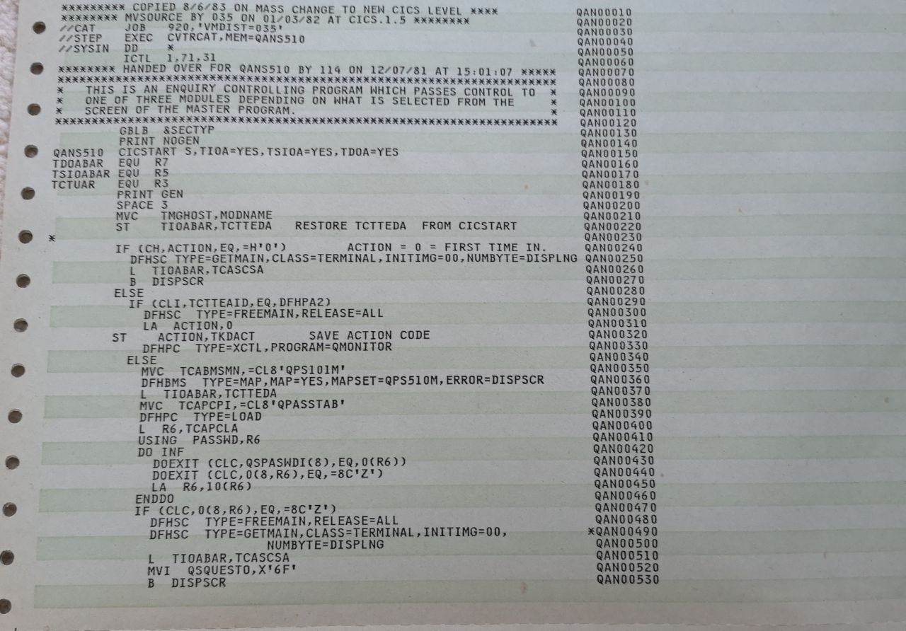 A printout from a compile job. |
Bit Order!
Because IBM hate us and want us to suffer, the official documents refer to the leftmost bit of a 32 bit value as bit 0 - on any other CPU it would usually be considered bit 31. We'll use the more common convention in these tutorials.
We'll specify LSB and MSB to be clear... LSB 0 will be the rightmost bit... MSB 31 will be the leftmost
| IBM Documentation written by drunk madmen Bit 31 is Least significant rightmost bit Bit 0 is Most significant leftmost bit |
Bit: 0.1.2.........29.30.31 MSB --------- LSB |
| Everyone else in the entire world ever Bit 0 is Least significant rightmost bit Bit 31 is Most significant leftmost bit |
Bit: 31.30.29.........2.1.0 MSB --------- LSB |
| Most Significant Bts | Least Significant Bits | |||||||||||||||||||||||||||||||
| Normal | 31 | 30 | 29 | 28 | 27 | 26 | 25 | 24 | 23 | 22 | 21 | 20 | 19 | 18 | 17 | 16 | 15 | 14 | 13 | 12 | 11 | 10 | 9 | 8 | 7 | 6 | 5 | 4 | 3 | 2 | 1 | 0 |
| Power PC | 0 | 1 | 2 | 3 | 4 | 5 | 6 | 7 | 8 | 9 | 10 | 11 | 12 | 13 | 14 | 15 | 16 | 17 | 18 | 19 | 20 | 21 | 22 | 23 | 24 | 25 | 26 | 27 | 28 | 29 | 30 | 31 |
| Bit Value | ... | ... | ... | ... | ... | ... | ... | ... | ... | ... | ... | ... | ... | ... | ... | ... | ... | ... | ... | ... | ... | ... | 512 | 256 | 128 | 64 | 32 | 16 | 8 | 4 | 2 | 1 |
| Register |
Details (suggested purpose) |
| R0 |
Subroutine Parameter / Hardwired Zero with addressing commands |
| R1 |
Subroutine Parameter / Parameter List |
| R2 |
Sometimes a Subroutine Parameter |
| R3 |
|
| R4 |
|
| R5 |
|
| R6 |
|
| R7 |
|
| R8 |
|
| R9 |
|
| R10 |
|
| R11 |
Our programs use this for the WTO buffer pos |
| R12 |
Our programs use this for USING |
| R13 |
Save Area for subroutines (like a stack) |
| R14 |
Return Address |
| R15 |
Subroutine Entry point register (The address we want to call) |
| IBM Bit | 0 | 1 | 2-4 | 5 | 6 | 7 | 8-11 | 12 | 13 | 14 | 15 | 16-17 | 18-19 | 20 | 21 | 22 |
23 |
24-31 | 32 | 33-63 |
| System Mask | Program Mask | PC | ||||||||||||||||||
| Purpose | 0 |
peR mask |
0 |
daT mode |
IO mask |
EXtern -al Mask |
PSW Key |
Type |
Machine check mask |
Wait state |
Problem state |
Address Space control |
Condition Code |
Fixed Point Overflw |
Decimal Overflw |
Exponent Underflw |
Signific ance |
0 |
Address -ing Mode |
Instruction Address |
| Normal Bit | 63 | 62 | 59-61 | 58 | 57 | 56 | 55-52 | 41 | 50 | 49 | 48 | 47-46 | 45-44 | 43 | 42 | 41 | 40 | 39-32 | 31 | 30-0 |
| Command |
CC=0 |
CC=1 |
CC=2 |
CC=3 |
| Maths |
=0 | <0 | >0 | Overflow |
| Compare |
Both Equal | R1 lower | R1 higher | unused |
| Logical ops |
=0 | !=0 | unused | unused |
| Format |
Addressing Mode |
Syntax | Meaning | Example |
| RR | Register | R1,R2 | R1=Destination Register R2=Register |
LR R0,R1 |
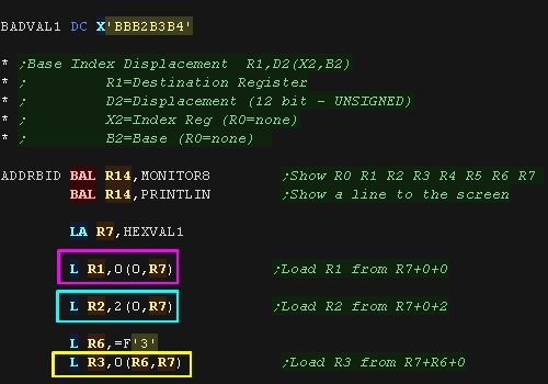
| RX | Base Index Displacement |
R1,D2(X2,B2) | R1=Destination Register D2=Displacement (12 bit - UNSIGNED) X2=Index Reg (R0=none) B2=Base (R0=none) |
L R3,4(R6,R7) |
| SI | Immediate | D1(B1),I2 | D1=Displacement (12 bit - UNSIGNED) B1=Base Register I2=Immediate (8 bit) |
MVI D1(B1),I2 |
| RS | Register Base Displacement |
R1,R3,D2(B2) | R3=Register 2 (not all commands use this, eg
SLDA) D2=Displacement (12 bit - UNSIGNED) B2=Base Register |
LM R1,R3,D2(B2) SLDA R1,D2(B2) |
| SS #1 | Sized (One Length) |
D1(L,B1),D2(B2) | D1=Displacement (12 bit - UNSIGNED) B1=Base Register L=Length (8 bit - count of bytes-1 (0=1 byte, 2=2 bytes etc)) D2=Displacement (12 bit - UNSIGNED) B2=Base Register |
MVC D1(L,B1),D2(B2) |
| SS #2 | Sized (Two Lengths) |
D1(L1,B1),D2(L2,B2) | D1=Displacement (12 bit - UNSIGNED) L1=Length (4 bit - count of bytes-1 (0=1 byte, 2=2 bytes etc)) B1=Base Register D2=Displacement (12 bit - UNSIGNED) L2=Length (4 bit - count of bytes-1 (0=1 byte, 2=2 bytes etc)) B2=Base Register |
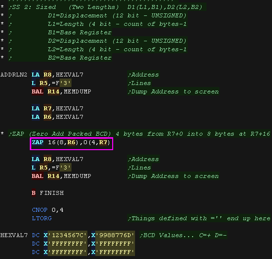
ZAP D1(L1,B1),D2(L2,B2) |
|
NAME OP
OPERANDS |
| Column | Purpose |
| 1-8 |
Name (Label) |
| 10-14 |
Operation |
| 16+ | Operands |
| 16 | Continuation of last line |
| 40+ | Remarks |
| 71 | End of code |
| 72 | Continue indication (72) - any char here defines multiline Next line starts from Column 16 |
A label cannot be on a line on its own, an operation must come after it!
* in ASM source = current line Address
|
DOMSG EQU * |
R1 EQU 1
R2 EQU 2
11111111112222222222333333333344444444445555555555666666666677777777778888888888 |
* I am a comment |
| BALR RetAddr,CallAddr | if CallAddr=R0 no jump occurs |
| USING Label,Reg | Define Reg as used for psuedo ops by assembler DROP releases the register |
| ORG | Set location counter |
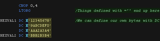
| LTORG | Literal org |
| CNOP limit,boundary | Conditional no-op (Spacing) If PC is greater than {limit} over a {boundary} byte boundary EG: "CNOP 0,4" will ensure we're 32 bit aligned |
| MACRO MEND |
Macro definition |
USING *,12 ;use R12 for Assembler Psuedo ops and macros for all code (* could be a label if you want multiple base registers, eg USING MyLabel,11)
Word 1: used by PL/I
Word 3: Used by Trace (Succeeding sub)
| Character | Purpose | Notes | Example |
| B | Binary | DC
B'11110000'
Value &F0 |
|
| C | Character | Character in EBDIC... not ASCII! | DC
C'ABC'
Value &C1,&C2,&C3 (EBDIC) |
| L | Length | Get the length of a value (or command line) | TEST BR R3
Two byte command |
| X | Hexadecimal | DC
X'FF'
Value 255 |
|
| = | Immediate In LORG pool |
Define value at LTORG, and put pointer in code |
L
R1,=X'FF'
This will point to the LTORG section |
| H | Halfword | 16 bit Value | DC
H'256'
Value &0100 |
| F | FullWord | 32 bit Value | DC
F'256'
Value &00000100 |
| L | Literal | Fixed Literal {Repeat}{Type}L{Total} Type {Type} is defined, padded to {Total} and duplicated {Repeat} times |
        DC
4CL3'A' |
| 0 | 1 | 2 | 3 | 4 | 5 | 6 | 7 | 8 | 9 | A | B | C | D | E | F | |
| 0x |
NUL | SOH | STX | ETX | SEL | HT | RNL | DEL | GE | SPS | RPT | VT | FF | CR | SO | SI |
| 1x | DLE | DC1 | DC2 | DC3 | RES/ENP | NL | BS | POC | CAN | EM | UBS | CU1 | IFS | IGS | IRS | IUS/ITB |
| 2x | DS | SOS | FS | WUS | BYP/INP | LF | ETB | ESC | SA | SFE | SM/SW | CSP | MFA | ENQ | ACK | BEL |
| 3x | SYN | IR | PP | TRN | NBS | EOT | SBS | IT | RFF | CU3 | DC4 | NAK | SUB | |||
| 4x | SP | � | . | < | ( | + | ||||||||||
| 5x | & | ! | $ | * | ) | ; | � | |||||||||
| 6x | - | / | � | , | % | _ | > | ? | ||||||||
| 7x | ` | : | # | @ | ' | = | " | |||||||||
| 8x | a | b | c | d | e | f | g | h | i | � | ||||||
| 9x | j | k | l | m | n | o | p | q | r | |||||||
| Ax | ~ | s | t | u | v | w | x | y | z | |||||||
| Bx | ^ | [ | ] | |||||||||||||
| Cx | { | A | B | C | D | E | F | G | H | I | ||||||
| Dx | } | J | K | L | M | N | O | P | Q | R | ||||||
| Ex | \ | S | T | U | V | W | X | Y | Z | |||||||
| Fx | 0 | 1 | 2 | 3 | 4 | 5 | 6 | 7 | 8 | 9 | EO |
Unpacked Binary coded decimal on IBM370 uses references to 'Zones' and 'Numerics'.... these sound complex, but simply refer to the high and low nibbles in each byte, For example:
$ZNZNZNZ or %ZZZZNNNN %ZZZZNNNN %ZZZZNNNN %ZZZZNNNN
For example, 'S' represents the Sign nibble in the following 7 digit examples: (Z=zone N=Numeric)
Zoned: $ZN ZN ZN ZN ZN ZN SN
| Digit |
Code |
Sign |
Code |
| 0 | 0000 | + ascii |
1010 (0xA) |
| 1 | 0001 | - ascii |
1011 (0xB) |
| 2 | 0010 | + ebdic |
1100 (0xC) |
| 3 | 0011 | - ebdic |
1101 (0xD) |
| 4 | 0100 | + | 1110 (0xE) |
| 5 | 0101 | + | 1111 (0xF) |
| 6 | 0110 | ||
| 7 | 0111 | ||
| 8 | 1000 | ||
| 9 | 1001 |
| DEC | Macro | |
DEC | Macro | |
DEC | Macro |
| 0 | EXCP XDAP |
49 | Reserved | 97 | No macro | ||
| 1 | PRTOV WAIT WAITR |
50 | Reserved | 98 | PROTECT | ||
| 2 | POST | 51 | SDUMP SDUMPX SNAP SNAPX |
99 | DYNALLOC | ||
| 3 | EXIT | 52 | RESTART | 100 | No macro | ||
| 4 | GETMAIN (TYPE 1) (get storage below 16 megabytes - with R operand) | 53 | RELEX | 101 | QTIP | ||
| 5 | FREEMAIN (TYPE 1) | 54 | DISABLE | 102 | AQCTL | ||
| 6 | LINK LINKX |
55 | EOV | 103 | XLATE | ||
| 7 | XCTL XCTLX |
56 | ENQ RESERVE |
104 | TOPCTL | ||
| 8 | LOAD | 57 | FREEDBUF | 105 | IMGLIB | ||
| 9 | DELETE | 58 | RELBUF REQBUF |
106 | Reserved | ||
| 10 | FREEMAIN (free storage below 16 megabytes) GETMAIN (get storage below 16 megabytes - with R operand) | 59 | OLTEP | 107 | MODESET | ||
| 11 | TIME | 60 | ESTAE STAE |
108 | Reserved | ||
| 12 | SYNCH SYNCHX |
61 | No macro | 109 | ESPIE IFAUSAGE MFDATA(RMF�) MFSTART(RMF) MSGDISP OUTADD OUTDEL |
||
| 13 | ABEND | 62 | DETACH | 110 | Reserved | ||
| 14 | SPIE | 63 | CHKPT | 111 | No Macro | ||
| 15 | ERREXCP | 64 | RDJFCB | 112 | PGRLSE | ||
| 16 | PURGE | 65 | Reserved | 113 | PGANY PGFIX PGFREE PGLOAD PGOUT |
||
| 17 | RESTORE | 66 | BTAMTEST | 114 | EXCPVR | ||
| 18 | BLDL (TYPE D) FIND (TYPE D) |
67 | Reserved | 115 | Reserved | ||
| 19 | OPEN | 68 | SYNADAF SYNADRLS |
116 | CALLDISP CHNGNTRY IECTATNR IECTCHGA IECTRDTI RESETPL |
||
| 20 | CLOSE | 69 | BSP | 117 | DEBCHK | ||
| 21 | STOW | 70 | GSERV | 118 | Reserved | ||
| 22 | OPEN (TYPE = J) | 71 | ASGNBFR BUFINQ RLSEBFR |
119 | TESTAUTH | ||
| 23 | CLOSE (TYPE = T) | 72 | No macro | 120 | FREEMAIN (free storage above 16 megabytes - TYPE 1) GETMAIN (get storage above 16 megabytes - TYPE 1) operand |
||
| 24 | DEVTYPE | 73 | SPAR | 121 | No Macro (for VSAM) | ||
| 25 | TRKBAL | 74 | DAR | 122 | EVENTS(TYPE 2) Extended LINK Extended LOAD Extended XCTL LINK - Extended LINK LOAD - Extended LOAD Service Processor Call STIMERE VALIDATE |
||
| 26 | CATALOG INDEX LOCATE |
75 | DQUEUE | 123 | PURGEDQ | ||
| 27 | OBTAIN | 76 | No macro | 124 | TPIO | ||
| 28 | Reserved | 77 | Reserved | 125 | EVENTS(TYPE 1) | ||
| 29 | SCRATCH | 78 | LSPACE | 126 | Reserved | ||
| 30 | RENAME | 79 | STATUS | 127 | Reserved | ||
| 31 | FEOV | 80 | Reserved | 128 | Reserved | ||
| 32 | REALLOC | 81 | SETDEV SETPRT |
129 | Reserved | ||
| 33 | IOHALT | 82 | Reserved | 130 | RACHECK | ||
| 34 | MGCR/MGCRE QEDIT |
83 | SMFEWTM,BRANCH=NO SMFWTM |
131 | RACINIT | ||
| 35 | WTO WTOR |
84 | GRAPHICS | 132 | RACLIST | ||
| 36 | WTL | 85 | No macro | 133 | RACDEF | ||
| 37 | SEGLD SEGWT |
86 | ATLAS (obsolete) | 134 | Reserved | ||
| 38 | Reserved | 87 | DOM | 135 | Reserved | ||
| 39 | LABEL | 88 | Reserved | 136 | Reserved | ||
| 40 | EXTRACT | 89 | Reserved | 137 | ESR(TYPE 6) | ||
| 41 | IDENTIFY | 90 | Reserved | 138 | PGSER | ||
| 42 | ATTACH ATTACHX |
91 | VOLSTAT | 139 | CVAF CVAFDIR CVAFDSM CVAFSEQ CVAFVOL CVAFVRF |
||
| 43 | CIRB | 92 | TCBEXCP | 143 | CIPHER EMK(TYPE 4) GENKEY RETKEY |
||
| 44 | CHAP | 93 | TGET TPG TPUT |
144 | No macro | ||
| 45 | OVLYBRCH | 94 | GTDEVSIZ GTSIZE GTTERM STATTN STAUTOCP STAUTOLN STBREAK STCC STCLEAR STCOM STFSMODE STLINENO STSIZE STTMPMD STTRAN TCLEARQ |
145 | Reserved | ||
| 46 | STIMERM(CANCEL OPTION) STIMERM(TEST OPTION) TTIMER |
95 | SYSEVENT | 146 | BPESVC | ||
| 47 | STIMER STIMERM(SET OPTION) |
96 | STAX | ||||
| 48 | DEQ |
JCL - Job Control Language
| Command | Format | Example | Purpose |
| JOB | //{Jobname} JOB ({Account num}) {operands} {comments} | //ASMFCLG JOB (001),'ASM HELLO
WORLD',
|
Job |
| EXEC | //{Stepname} EXEC {program} {operands} {comments} | //HELLO EXEC ASMFCLG |
Execute |
| DD | //{dd name} DD {operands} {comments} | //ASM.SYSUT1 DD UNIT=SYSDA |
Data Definition |
| PROC | //{name} PROC {operands} {comments} | //DEF PROC STATUS=OLD,LIBRARY=SYSLIB,NUMBER=777777 |
Procedure |
| PEND | //{name} PEND {comments} | // PEND |
Procedure End |
| /* //* |
/* I am a comment | Comment |
JOB:
Class = Time slicing class (A=Default) PRTY = Priority
MSGCLASS = Output class (A-z / 0-9)
MSGLEVEL= (statements,messages) .... 1,1 = output all
Region= Memory to allocate in 1024 byte blocks (eg 128K)
DD:
* = Prompt for input (//ddname DD *)
UNIT = device / group containing data set
Server console / Terminal Notes
Server
Start Server:
C: ipl 150
T: enter
T: r 0,u
T: r 1,format,noreq
to stop errors (in console)
OSTAILOR QUIET
To reply to a message:
r <message number>,<response>
Rexx Files:
regina condcode.rexx prt00e.txt smp4p44
Telnet
Ctrl ]
set localecho
enter
F12 to continue read of messages
shutdown: (in telnet)
$p jes2
z eod
quiesce
quit (in console)
Tape to asci?
hetget -a tape/stage1.het stage1.output 1
 |
Warning!
Windows Defender may detect 'NCAT' as a 'threat' and delete it!! Without it the scripts won't be able to send the ASM jobs to the server, so you'll need to restore it if it does. The version provided is the one which came with Hercules, but obviously use it at your own risk. |

| Lesson
1 - Getting started with the IBM370 Lets get started with the IBM 360/370!... we'll learn the basics of the CPU and see a sample 'Job file' that we can use to run our program. |
 |
 Lesson1.asm
|
|
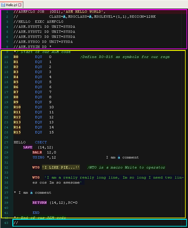
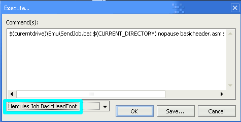
| An ASM file cannot be assembled on its own, we
need to send a JCL Job file to the server. The Job commands start // Here is the minimal Header and Footer to a JCL which will assemble and run our program. The ASM source code is in the middle of this JOB script These are only ASM tutorials... We will not go into details of JCL in these tutorials To build this JCL file, use the Hercules Job option in my devtool scripts |
 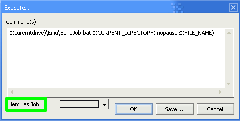 |
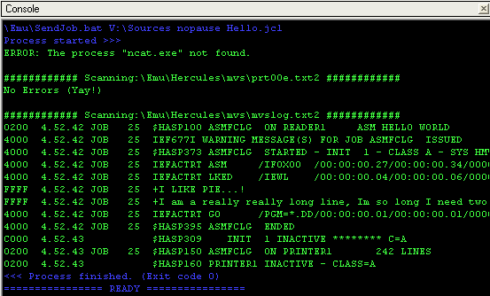
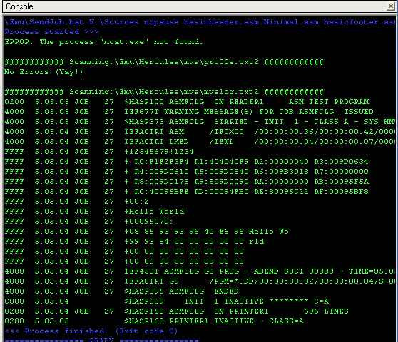
| If you use my build scripts, the results of the assembly will
be shown in the console window I've written some tools to scan the PRT00e printer output for possible assembly errors and show them onscreen The output is then shown on the screen |
 |
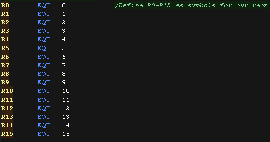
| Lets take a close up look at the ASM file. First we define R0-R15 as numbers 0-15... we'll use these for our registers to make them clearer. |
 |
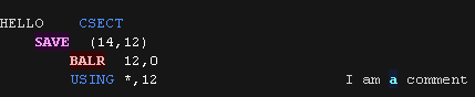
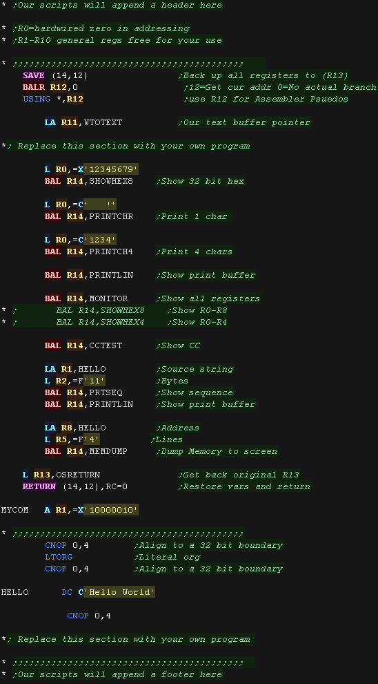
| Here is the first part of our code... We'll discuss all these
commands later, but for now look at the following! See the HELLO text at the left? This is a LABEL - it must be at the far left... there must also be some kind of command after it (like CSECT) See I AM A COMMENT? it comes after some commands - so is treated as a comment by the assembler. I will usually prefix comments with a semicolon ; however this is just so notepad++ colors them nicely! |
 |
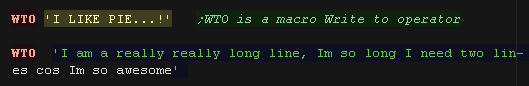
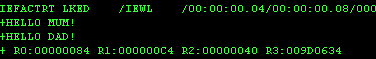
| WTO is a macro for 'Write to operator'... here we use it to
declare our love of pie! The second line is very long... These Job files were originally input in to the server via punched cards... Column 76 has a special purpose... any symbol here (in this case a - ) defines a line as continuing on another line. |
 |
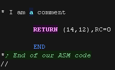
| Here is a full line comment. a * at the far left of a line
defines it as a whole line comment. (A normal comment has to come after a command) |
 |
| If you want a template to do your own
experementation, take a look at Minimal.asm This file includes a set of examples showing various test we can do, and is the basis of all the lessons in these tutorials. We won't cover the commands here... as we'll use them all over the following lessons. This ASM file needs a Job header and footer, and should be assembled with the Hercules Job BasicHeadFoot option in my ASM build scripts. This option attaches a header and footer with various assisting functions and declarations. |
  |
| Here are the results, Various Register and Memory dumps were performed as well as character prints were performed. These will all be used during our tutorials so we can see what the processor is doing. |
 |
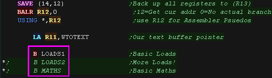
| Here is the start of Lesson 1.asm This starts with a set of Branch commands to the various examples. Uncomment one (Move the *; ) to try out the different examples |
 |
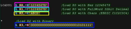
| Lets try out some LOADS with L (L=Load!) The destination register is on the Left of the comma ... the source is on the right Here we've loaded 5 'Literals' with =... =X loads a hexidecmal value =F loads a 'full' 32 bit value =C loads a Character value WARNING! This is EBDIC not ASCII because IBM hate us and want to make us suffer! =B loads a Binary value |
 |
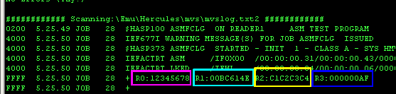
| Here are the results. Registers R0, R1 R2 and R3 were loaded with the valuese we specified |
 |
 |
When we
specify a value with = like this , it's not actually stored in
the command itself, it's stored somewhere further down at the
Literal ORG...(LTORG) Don't know what that means? don't worry about it yet... we'll cover it later! |
| We can use R0 as a destination just fine like this,
but R0 has a special purpose when used as a source address... in
addressing commands it's a 'Hardwired zero'... meaning whatever
value R0 has, it will be treated as 0 for some commands. For now just bear it in mind, as if you're doing your own testing, R0 may not work as expected, so better to use R1-R10 instead. |
 |
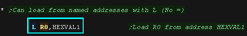
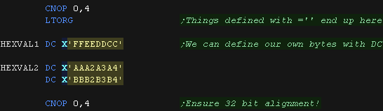
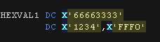
| If we don't use =, then L can be used to load from an address. Here we defined a 32 bit hex value with DC and gave it the label HEXVAL1 We then loaded from HEXVAL1 into R0 |
  |
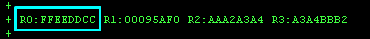
| Here is the result |
 |
| We
specified L R0,HEXVAL1 here, but the IBM370 can't specify an
address like this, so again the assembler will change this! We had the command "USING R12,0" at the start of the code, because of that the assembler will use R12 as the current code address with relative offset to the data, and load from that address with the assembled command. This is all pretty complex, so don't worry about it now, as the assembler does the work for us... but it's important to have some understanding of what goes on 'Behind the scenes' |
 |
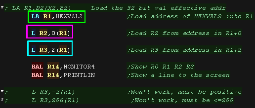
| Actually when we specified a label, the assembler will calculate
an offset for us, but actually all Loads actually work from an
address in one or more registers and a fixed positive integer
offset of up to 255 We can use LA to Load an Address... here we load address 'HexVal2' into R1 Here we load a 32 bit value from the address in register R1 into R2 (with offset 0) We also load from the the address in register R1, plus immediate value 2 into R3 2(R1) takes the value in register R1, adds 2 to that value, and loads from the resulting address. R1 is not affected by this calculation. |
  |
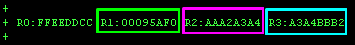
| Here are the results |
 |
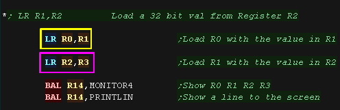
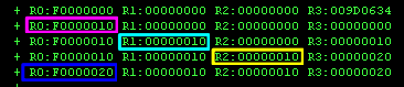
| We can copy a value from one register to another with LR Load Register will copy from the register on the right of the comma, to the one on the left. Here we copy R1 into R0, and R3 into R2 |
 |
| Here are the results |
 |
|
Psst... wanna know a secret? On the IBM370, When a command ends with R, the source is a Register ... otherwise it's usually an address ( offset+ address in Register) For Example. L loads into a register from an address... LR loads into a register from an register! |
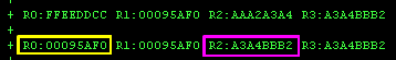
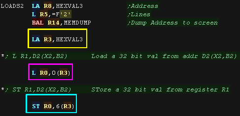
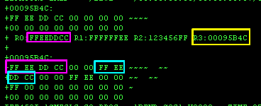
| Ok, lets load the address of
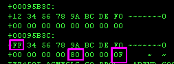
some test data into R3. We'll load from the address in R3 + 0 into R0, Then we'll store R0 to the address R3 + 6 |
 |
| Here are the results |
 |
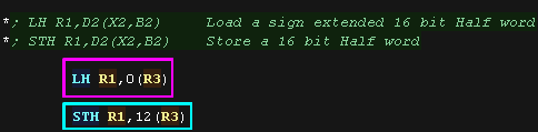
| We've been loading full 32 bit values up until now, but we can
also load smaller values. LH will Load a 16 bit Half word STH will store a 16 bit half word. The half is sign extended, meaning the top bit of the half fills the remaining top 16 bits of the register. |
 |
| Here are the results | 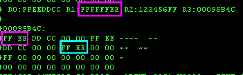 |
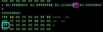
| On the IBM370, A single 8 bit byte is referred to as a
Character. IC will Insert an 8 bit 'Character' value into a register... it Insert's it into the bottom 8 bits, leaving the top 24 bits of the register unchanged. STC will Store an 8 bit 'character' from the bottom 8 bits of a register into memory |
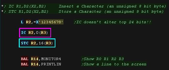 |
| Here are the results |
 |
| Of course, Just loading values isn't much use, so we'll want to
do some calculations. We can add or subtract one register from another with AR (Add Register) or SR (Subtract Register) As before, the destination is on the left of the comma, and the parameter to be added or subtracted is on the right. |
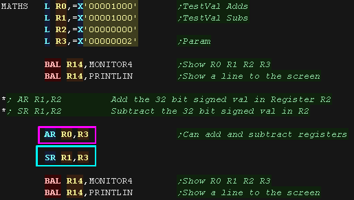 |
| Here are the results |
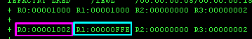 |
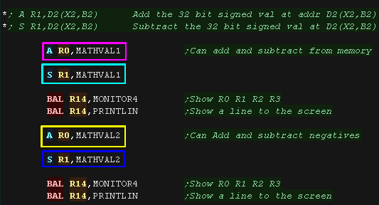
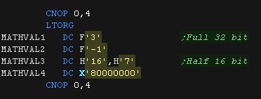
| Of course, we can add and subtract 32 bit values from memory
too! A (add) and S (subtract) will do this. We can also Add and Subtract negative numbers! |
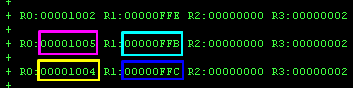
  |
| Here are the results |
 |
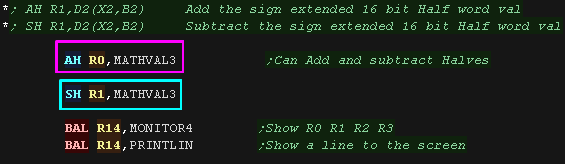
| We may want to use 16 bit values in memory, these are sign
extended and used as the parameter AH will Add a 16 bit Half SH will Subtract a 16 bit Half |
 |
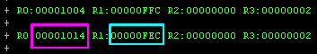
| Here are the results. |
 |
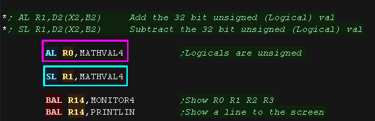
All the Addition and Subtraction commands we've looked at here are designed for signed numbers. Unsigned numbers are referred to as 'Logical' AL will Add a Logical (Unsigned) number from memory and SL will Subtract a Logical (unsigned) number from memory |
 |
| Here is the results | 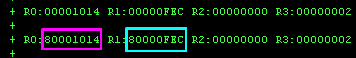 |
| We can use ALR to Add
Logically from a Register and SLR
to Subtract Logically from a Register The difference between AR/SR and ALR/SLR is how the Condition Codes CC are set. Algebraic (Signed) addition and Subtraction with AR and SR will set CC=3 when an 'Overflow' occurs, this is when too big a value has been added/subtracted, and the top bit changed, unintentionally causing the sign to change. |
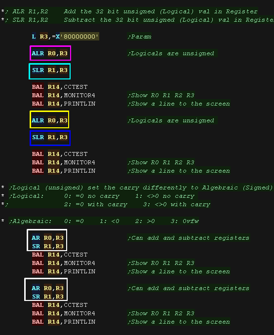 |
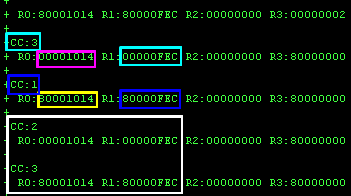
| Here are the results. Notice, the shown CC flags were set by the subtract command. |
 |
 |
On the IBM
370, the CC flags are just two bits, so always have a value 0-3 What these values mean depends on the command that was just executed, and some commands don't set the flags at all! When you want to use the CC flags to make a decision, You have to read the documentation to understand what the CC flags mean depending on the commands you're using |
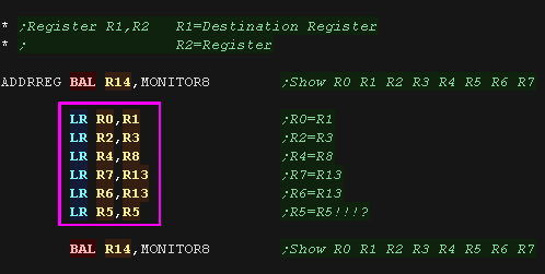
| Register addressing is the
simplest there is! The Source parameter (the one after the comma) is another register. The Destination is another register. Here we use LR to load the values from various registers into other registers |
 |
| Here are the results | 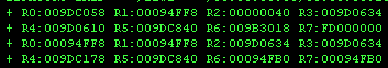 |
| Warning! Registers R11-R15 have special purposes in
our code! You can use them as sources (after the comma), but if you change the values they contain, bad things may happen! You have been warned!!!! |
|
| Whether we know it or not,
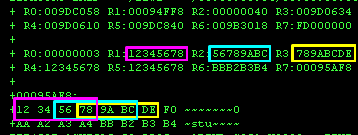
this is actually the most common addressing mode we'll use! This takes three values... Two are registers, and the final parameter is an unsigned 12 bit displacement (Number value) If the 'X2/B2' parameter is R0, then the 'X2/B2' parameter has the value zero, whatever the actual value in R0 - R0 is a hardwired zero in this case Here we have three examples. The first uses two zero parameters, so R1 is loaded from the address in R7 The second uses a Displacement of 2, so R1 is loaded from the address in R7+2 The third loads from the address in R6+R7, the displacement is zero |
  |
| Here are the results |
 |
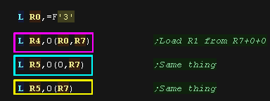
| R0 is a hardwired zero, we can specify it via our symbol
R0, by number 0, or omit it. However we must specify the displacement even if it is zero. |
 |
| Here are the results |
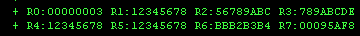 |
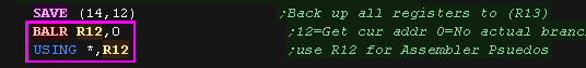
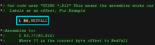
| Actually, we'll often end up using this addressing mode without
knowing it! When we specify an address for a parameter, the assembler converts this into the form D2(X2,B2) at the start of our code we had USING *,R12 - This tells the assembler it can use R12 for address calculations. BALR R12,0 loads the current address into R12 Here we use "L R6,HEXVAL2", however the assembler converts this using R12 as a base (from the USING statement), and the offset to HEXVAL2 |
  |
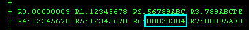
| Here is the result |
 |
| Here is the line in the assembly listing |  |
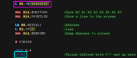
| We've defined literals with commands like L
R0,=X'66606670' before... These = literals are also D2(X2,B2) type commands! The assembler stores the value we specify at LTORG, and puts a reference in the assembled byte code of command |
 |
| The register was loaded with the value we specified | 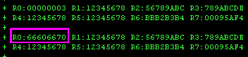 |
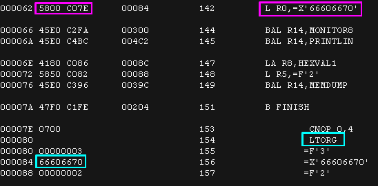
| Here is the resulting assembled code. Notice the value '66606670' does not appear in the bytes of the command, they were stored at the LTORG location! |
 |
|
There can be
more than one LTORG in a program... In fact you may need them! As the offset to the data is only 12 bit, so if the LTORG is too far away they assembler to calculate an offset. |
SI: Immediate - D1(B1),I2
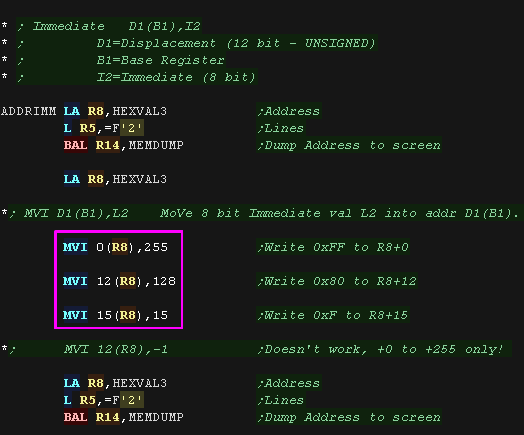
| Immediate addressing uses an
8 bit unsigned immediate as the second parameter. As before, the destination is on the Left of the comma, however this time the destination is a memory address, specified by a register (B1) and a numeric offset (D1) here we use a new command... MVI - MoVe an Immediate - Writing an 8 bit immediate value into an destination address Here we write 3 immediate bytes to memory via 3 MVI commands |
 |
| Here are the results |
 |
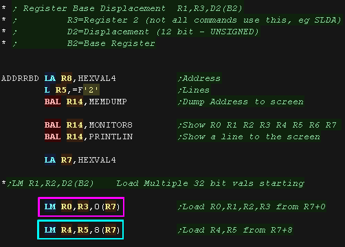
| The Destination for this command is a register, but a second
register parameter, and a Register+Displacement are also available
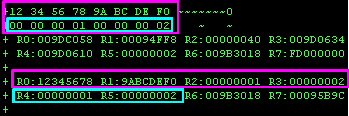
as parameters. Here we use LM - Load Multiple This command loads a sequence of consecutive registers from a memory address, we use it twice here. We'll look at this command again next lesson |
 |
| Here are the results |
 |
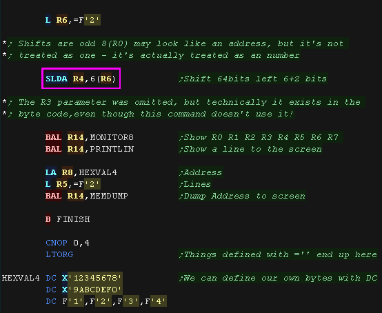
| Here we use SLDA (Shift Left Double
Algebra) - This shifts the 64 bit value two registers
left for Algebra Algebra means 'signed numbers' - it would be called Arithmetic on other CPUs! This command is very weird!... 6(R3) looks like an address specification (which it is) but this command uses the 'address' as a bit count, the value at the 'address' is never used. BUT WAIT!... Where's the R3 I hear you shout! Well, it's not there, but it does technically exist on this command in the assembled bytes. |
 |
| The 64 bits in R4+R5 were shifted 8 bits (one nibble) |
 |
|
Why are we mentioning this SLDA command
here if it doesn't use the R3 register? Well it's technically part of the 'RS' format commands. These 'Formats' define the purposed of the bits in the resulting assembled commands. In this case, although present in the asesembled byte, the 4 'R3 bits' of the SLDA commands bytes have no function. |
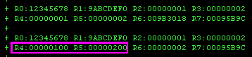
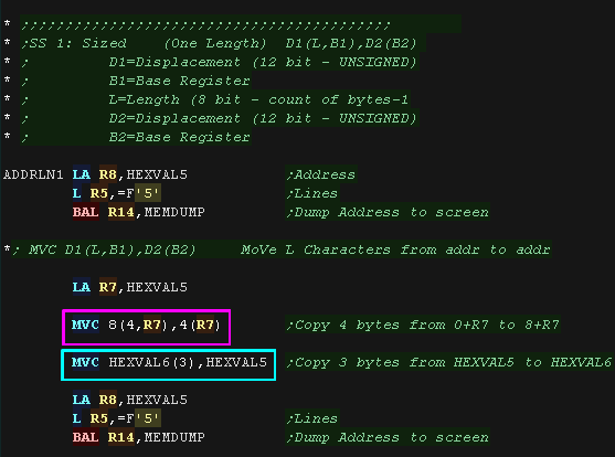
| Some commands work with a sequence of bytes, These will use the
specification of a single length L in bytes Here we use MVC - move Characters (Characters are the IBM 370 name for bytes!), we copy 4 bytes to R7 from R7+4 As the same number of bytes are read from the source as written to the destination, the byte parameter is only needed once, it appears before the comma inside the brackets before the register containing the address We use the MVC command a second time, this time using address labels, we copy 3 bytes this time! |
  |
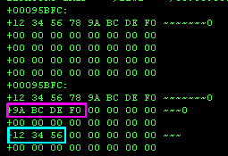
| Here are the results! |
 |
| There be many times we may want to use a fixed value in multiple
places in our code, but know it may change later. For example, suppose we have a block of data, 4 bytes in length we use in various places... What if one day we increase it to 5 bytes? We don't want to have to search all our code and change lots of 4s to 5s... instead we can define a named Symbol! A symbol is similar to a label an is defined with EQU... here we define LENDEF = 4, and use it as the length to copy with a MVC command! |
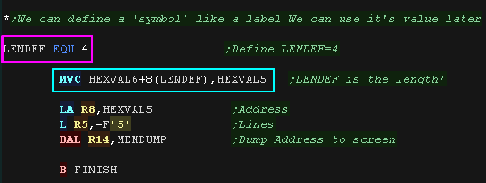 |
| Here is the results! |
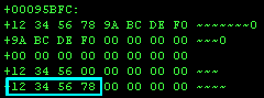 |
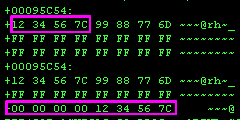
| Sometimes one length isn't enough! So why not have 2!?? The IBM370 has a wide variety of 'Decimal' commands... these are for working with Binary Coded Decimal. We'll look at BCD more later in Lesson 6, but for now we'll try out two lengths with ZAP ZAP is Zero Add Packed... which copies Packed (two digits per byte) decimal values from one place to another. L2 specifies the length of the source BCD, and L1 specifies the length of the destination. This can be used for 'Resizing' Decimal values. |
 |
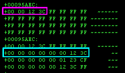
| We expanded the 4 byte source into an 8 byte destination! |
 |
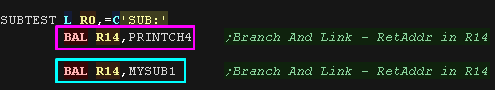
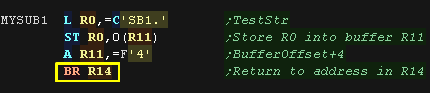
| Like many RISC systems, when calling a subroutine the IBM370
stores the 'return address' in one of it's registers. BAL will call a sub, storing the return address in the specified register. To return from that sub we Branch to that Register (BR) Here we run two subs, 'PRINTCH4' - which is part of my testing tools, and MySub1, which is shown here. We called the subs with BAL R14, so we return with BR R14 |
  |
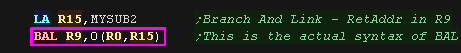
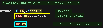
| Actually, like other commands, when we specify a label, the
Assembler is converting it to an offset with the register we
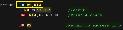
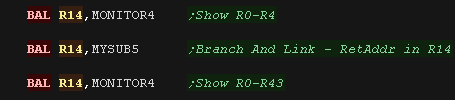
specified with USING Here is the actual BAL command, this time we're calling MYSUB2, with the return address in R9. This is important, because we've nested the PRINTCH4 routine, calling it with R14 as the return, If we used R14 both times, the second return would fail, as the true return address for MySub2 would have been lost. |
  |
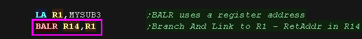
| There is an alternative command BALR,
This execute the subroutine in the second parameter (after the
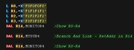
comma) This command assembles to two bytes, rather than the 4 used by BAL, so it may save code space if you are using many references to the same destination We want to call a subroutine again, but this time we'll 'protect' R14 by transferring it's value into R9 in the called sub |
  |
| Here are the results. |
 |
| OK, so backing up our return register is one problem... but
there may be times we need to 'protect' other registers from being
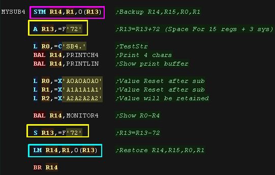
changed. STM (Store Multiple) and LDM (Load Multiple) can do this for us! We specify a range of registers and a destination (R13)... the registers will be backed up in ascending order by STM, or restored by LDM. Note, neither of these commands alter the destination (R13)... so we need to use an A and S command to alter it's value... Here we are protecting R14,R0 and R1, which are restored after the subroutine completes. Adding and subtracting a total of 72 is safest, as this is a 'full compliment' of registers + a few special system ones... We don't need that much space, but this is what the IBM370 will expect us to do! |
  |
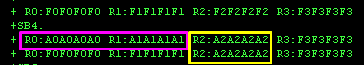
| R0 and R1 were restored by the STM/LDM command so their value
was unchanged after the sub. R2 was not included in the range R14...R1 used with STM/LDM so it was changed by the subroutine. |
 |
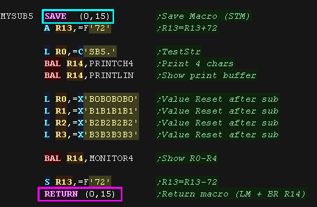
| As this is something we will often do, the assembler provides SAVE and RETURN
macros to help us. SAVE will back up a sequence of registers. RETURN will restore them and return - Assuming the return address is in R14 |
  |
| Here is the result... this time we protected ALL the registers! | 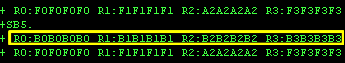 |
 |
SAVE and RETURN apply offsets to the data stored
and restored based on the default layout of the save area... so
it's safest to add and subtract 72, whatever number of registers
you're working with. |
| We can call out to operating
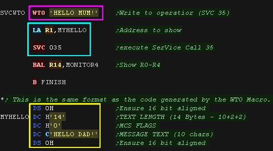
system functions using the SVC command. The most common of these is SVC 35, which is used by the WTO macro (Write to Operator). Here we use WTO to write a message to the screen. As mentioned, this is a macro, and actually expands to a command, and a block of data, This second example shown here was based on the expanded code of WTO from the listing file! |
 |
| The WTO command (SVC 35) Showed both our messages to the screen. |
 |
The Count of IBM 370!
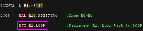
| There will be a great many times when we want to do a simple
loop... like a 'FOR' loop in basic. The IBM 370 provides the BCT command for simple loops, this decrements a specified register, and branches back to the specified address until the register reaches zero. |
 |
| Here the loop repeated until R1=0 | 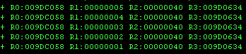 |
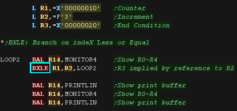
| There are more advanced commands! BXLE is Branch on indeX Less or Equal We specify two registers and an address... however the second register reference (R2) is special! R2 in this example specifies the source PAIR of registers the odd companion to this register (R3) is also used! R2 is added to R1, and the total is stored in R1, This value is compared to R3, if the value in R1 is less or equal (BXLE) to R3 then a branch occurs to address D2(B2). |
 |
| BXLE repeated until R1 went over R3 (20)... incrementing in
stages of R2 (3) |
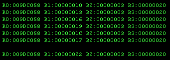 |
| BXH is Branch on indeX Higher.
it works in the same way as BXLE, with the condition reversed It would be expected that R2 would be negative. |
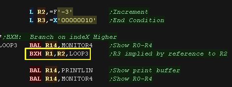 |
| BXH repeated while R1 was higher than R3 (1) adding R2 (-3) each time | 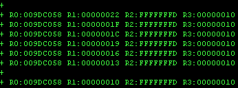 |
| As there are a
limitless combination of parameters, and conditions, You need to
try out the conditions yourself to really get an understanding
of how they work! So download the lesson and devtools and try it
out for yourself! Actually you should be doing that for all the lessons... but we know people are lazy!!! |
|
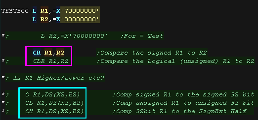
| If we want to compare two registers - with the intent on running
different commands based on the result via a branch - we can use
one of the Compare commands! There are a variety depending on what we want to compare! If both our parameters are in registers we can use.... CR R1,R2 will Compare the signed R1 to R2 CLR R1,R2 will Compare the Logical (unsigned) R1 to R2 If one of our parameters is in memory we have 3 options.... (One parameter must be in a register!) C R1,D2(X2,B2) will Compare signed R1 to the signed 32 bit value in memory CL R1,D2(X2,B2) will Compare unsigned R1 to unsigned 32 bit value in memory CH R1,D2(X2,B2) will Compare 32bit R1 to the SignExt Half value in memory |
 |
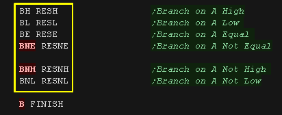
| The Compare commands will set the 2 bit condition code CC (with
a value of 0-3) Considering the two parameters compared A,B BH D2(X2,B2) / BHR R1 will Branch on A Higher than B BL D2(X2,B2) / BLR R1 will Branch on A Lower than B BE D2(X2,B2) / BER R1 will Branch on A Equal to B BNH D2(X2,B2) / BNHR R1 will Branch on A Not Higher than B BNL D2(X2,B2) / BNLR R1 will Branch on A Not Lower than B BNE D2(X2,B2) / BNER R1 will Branch on A Not Equal to B |
 |
| In this case we compared R1=0x70000000 to R2=0x80000000 The "CR R1,R2" compare was performed, and the condition codes caused the branch "BH RESH" to execute... R1 was decided to be Higher than R2! But why? Isn't "0x80000000" higher than "0x70000000" - Well not if it's a signed number, as 0x80000000 is negative and 0x70000000 is positive! "CR R1,R2" compares signed numbers, "CLR R1,R2" compares unsigned numbers - in which case R1 was Lower! |
With CR R1,R2: With CLR R1,R2  |
| Actually the Bcc commands are actually psuedo-ops using the more
complex BC command. This takes a 4 bit mask, each bit matches a possible value of CC (0,1,2 or 3 for the left-right bits) a 1 bit in the mask with a matching CC value causes the branch to occur CC M1
mask Psuedo ops |
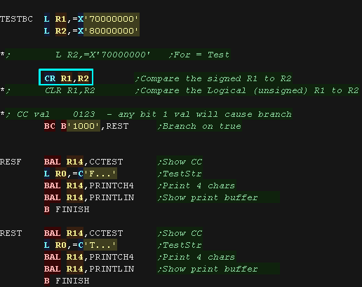 |
| In this case our mask was '1000', so only CC=0 would cause a
branch (branch on equal) The two values didn't match, so the branch did not occur However if we change the mask to '1010', the branch will occur if CC=0 or CC=2 |
with BC B'1000',REST: with BC B'1010',REST:  |
Note: Although the CC flags only contain a value 0-3, The meaning of these values varies depending on the executed command. There are more Bcc commands for use after other mathematical commands.
| (after arithmetic) BP D2(X2,B2) / BPR R1 Branch on Plus BM D2(X2,B2) / BMR R1 Branch on Minus BZ D2(X2,B2) / BZR R1 Branch on Zero BO D2(X2,B2) / BOR R1 Branch on Overflow BNP D2(X2,B2) / BNPR R1 Branch on Not Plus BNM D2(X2,B2) / BNMR R1 Branch on Not Minus BNZ D2(X2,B2) / BNZR R1 Branch on Not Zero BNO D2(X2,B2) / BNOR R1 Branch on Not Overflow |
(after mask test) BO D2(X2,B2) / BOR R1 Branch if Ones BM D2(X2,B2) / BMR R1 Branch if Mixed BZ D2(X2,B2) / BZR R1 Branch if Zero BNO D2(X2,B2) / BNOR R1 Branch if Not Ones BNM D2(X2,B2) / BNMR R1 Branch if Not Mixed BNZ D2(X2,B2) / BNZR R1 Branch if Not Zero |
Bit shifts are very useful in assembly! The help us move and isolate a few bits in a parameter, when we want them in a different place, but they also allow us to do quick multiplication or division by two!
Every time we shift the bits left by 1 bit, the value shifted will double.
Every time we shift the bits right by 1 bit, the value shifted will have!
This is a very fast way of multiplying and dividing by powers of 2, But there's a catch!
While there are no concerns shifting left, When we're working with a signed number and we shift to the right, we need to make sure the sign stays the same... If we shift in a 0, our negative value will become positive.
To solve this we have two types of shift:
'Logical shifts' for unsigned numbers, these always shift a bit 0 in when shifting right
'Algebraic shifts' for unsigned numbers, these keep the top bit the same when shifting right. These would be called Arithmetic shifts on other CPUs.
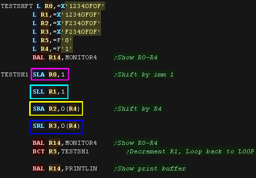
| The Shift commands on the IBM370 are a bit irregular in the way
they use the parameter. D2(B2) is a combination of a register value B2 + an immediate D2... however unlike other cases this is NOT an address specification, the result of the calculation is used as a bit shift number! In this example we're trying 4 shifts: SLA R1,D2(B2) Shift R1 Left for Algebra by D2(B2) bits SRA R1,D2(B2) Shift R1 Right for Algebra by D2(B2) bits SLL R1,D2(B2) Shift R1 Left Logically by D2(B2) bits SRL R1,D2(B2) Shift R1 Right Logically by D2(B2) bits |
 |
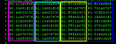
| Here are the results... Notice the values in the registers for
SLA and SLL are identical as there is no difference on the values
in these two commands. However SLA does do one thing SLL does not! SLL does not change the condition codes CC, however SLA sets them as follows: Condition Codes: 0: Result =0 1: Result <0 2: Result >0 3: Overflow |
 |
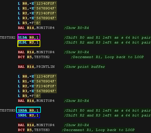
| Sometimes 32 bits just aren't enough, so for this we have 4
commands!: SLDA R1,D2(B2) Shift Left Double 64 bit val R1a:R1b for Algebra SLDL R1,D2(B2) Shift Left Double 64 bit val R1a:R1b Logically SRDA R1,D2(B2) Shift Right Double 64 bit val R1a:R1b for Algebra SRDL R1,D2(B2) Shift Right Double 64 bit val R1a:R1b Logically These will shift a 64 bit 'Double' pair of registers. When we specify a destination register like R0, the following register R1 will also be used as part of a 64 bit pair in the format R0:R1. |
 |
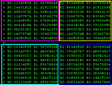
| Here are the results! |
 |
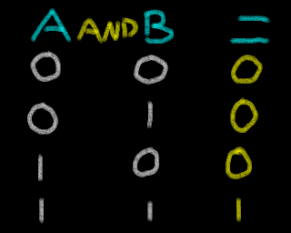
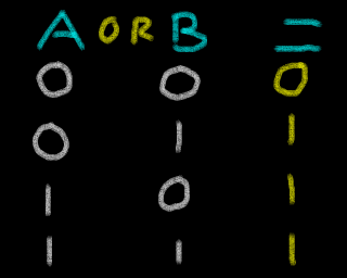
| aNd | Or | Xor (eXclusive or) |
 |
 |
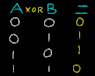 |
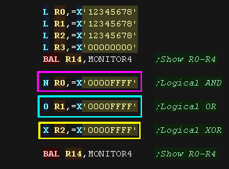
| As usual we have logical operations which work with the
destination in a register, and a parameter in memory addressed in
the form: Base,Index,Displacement....D2(X2,B2) Here we use the commands: N R1,D2(X2,B2) aNd R1 with the val at addr D2(X2,B2) O R1,D2(X2,B2) Or R1 with the val at addr D2(X2,B2) X R1,D2(X2,B2) XOR (bitflip) R1 with the val at addr D2(X2,B2) |
 |
| Here are the results. |
 |
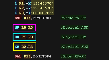
| We have commands where the parameter and destination are both
registers: NR R1,R2 aNd the register R1 with register R2 OR R1,R2 Or the Register R1 with register R2 XR R1,R2 eXclusive or the register R1 with register R2 |
 |
| Here are the results. | 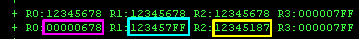 |
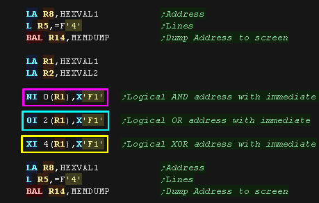
| If we want to perform operations on a destination Byte in memory
we can use the immediate commands! These take an unsigned 8 bit immediate byte parameter, and a destination memory address in the format Displacement+Base D1(B1) Here we use the commands: NI D1(B1),l2 aNd the byte at D1(B1) with 8 bit unsigned Imm I2 OI D1(B1),l2 Or the byte at D1(B1) with 8 bit unsigned Imm I2 XI D1(B1),l2 Xor the byte at D1(B1) with 8 bit unsigned Imm I2 |
 |
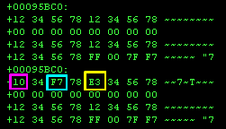
| Here are the results, 3 bytes in memory were changed. |
 |
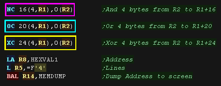
| We have an even more advanced set of commands. These will use a sequence of bytes from an address as the parameter, and a second set as the mask in the format D1(L,B1),D2(B2) ... D1(B1) is the Destination, D2(B2) is the parameter, L is the byte count. Here we use the following commands: NC D1(L,B1),D2(B2) aNd L Characters (bytes) from addr OC D1(L,B1),D2(B2) Or L Characters (bytes) from addr XC D1(L,B1),D2(B2) Xor or L Characters (bytes) from addr |
 |
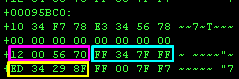
| Here are the results |
 |
| On many systems we will use the AND logical op to test bits. The IBM370 has a more powerful command... TM - Test Mask. This takes an 8 bit immediate and memory address. The 8 bits at the destination are tested with the mask and the CC flags are set based on the result: Here we use TM three times, with 3 different masks on the same destination |
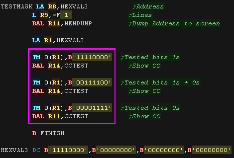 |
| We tested the destination 0b11110000 with 3 masks, here are the results! |
 |
| Tjere may be times we want to flip the sign of a value. 'Flipping the sign' in assembly can be called the 'two's complement'... and the IBM370 has a command LCR to flip the sign of a register! Here we use it to repeatedly flip values! |
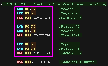 |
| We loaded the negative of R2 and R3, then we repeatedly flipped R0 and R1 from a positive to a negative | 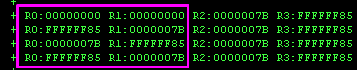 |
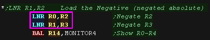
| If we don't know the sign of the source, but we want a negative
result we can use LNR. This will load negative version of a signed value, whatever its sign was before. |
 |
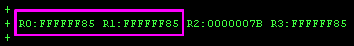
| Here are the results... R0 and R1 were loaded with
negative numbers from R2 and R3 |
 |
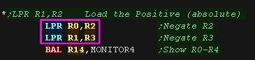
| If we want a positive value (an Absolute) we can use LPR
This will load a positive version of a signed value |
 |
| Here are the results... R0 and R1 were loaded with positive numbers from R2 and R3 | 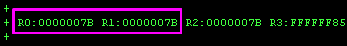 |
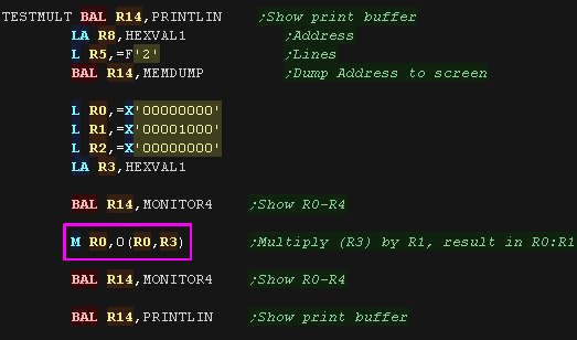
| The IBM 370 has many multiplication commands, They work with
either 16 or 32 bit source parameters, and give a 32 bit or 64 bit
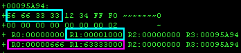
result. Where the result is 64 bit, we only specify one register, and the following register is used for the second half of the 64 bit value (We'll call these registers R1a:R1b) For example, if we use R0 with a 64 bit calculation R0 will be the High half, and R1 will be the Low half of the 64 bit result. Here we use the command M R1,D2(X2,B2), it gives a 64 bit result of multiplying two 32 bit parameters This will multiply 32 bit val in R1b (register after R1) by the 32 bit val at addr D2(X2,B2) stores the 64 bit result into R1a:R1b. Effectively performing R1a:R1b=R1b*D2(X2,B2) |
  |
| Here we multiplied 0x66663333 by
0x1000, the result was stored in R0:R1 |
 |
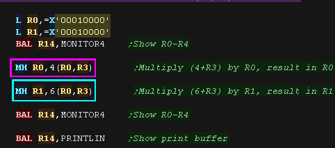
| This time we'll multiply a 32 bit register by a 16 bit signed
half in memory. We use MH R1,D2(X2,B2) This will multiply 32 bit R1 by the sign extended 16 bit Half word val at addr D2(X2,B2) store in R1 We try the command Twice! |
 |
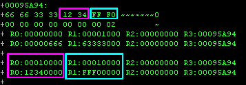
| Here are the results! |
 |
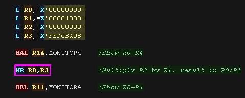
| If we don't want to work with memory, we can also use just
registers to calculate a 64 bit result of multiplying two 32 bit
registers. Here we use MR R1,R2 This will multiply 32 bit R1b by the 32 bit R2 and stores the 64 bit result into R1a:R1b Effectively R1a:R1b=R1b*R2 |
 |
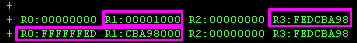
| Here are the results |
 |
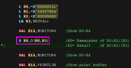
| Division commands store a two part result of division. The first part is the integer result of the division... the second part is any remainder. The first command we'll look at is 'D R1,D2(X2,B2)'... this will Divide a 64 bit register pair, by a 32 bit value at an address... The Result is stored in the second register of the pair, the remainder in the first. Effectively The result R1b=R1a:R1b/D2(X2,B2) The remainder R1a=R1a:R1b MOD D2(X2,B2) |
 |
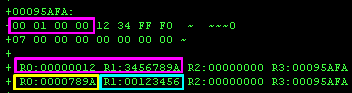
| Here is the result, The 64 bit register
value was divided by the 32 bit memory value The result was in the second register (R1)... the remainder was in the first (R0) |
 |
| We also have a register divide command. DR
R1,R2 This divides a 64 bit value in a register pair by a second single 32 bit register. The result is stored as a 32 bit integer result and remainder in the pair of registers. Effectively R1b=R1a:R1b/R2 R1a=R1a:R1b MOD R2 . |
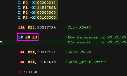 |
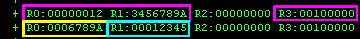
| Here is the result, The 64 bit register
value was divided by the 32 bit register value The result was in the second register (R1)... the remainder was in the first (R0) |
 |
|
There aren't
so many options when it comes to division as there were with
multiplication. Also remember shifting left and right halves and doubles numbers! Often bit shifting commands will be faster if you only need to work in powers of two. |
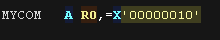
| The EXecute command will run a single command at a specified
address... this is not a call or jump, execution continues after
the EX command. We also specify a register... R0 is a hardwired zero, so if we use EX R0,addr, then nothing else will happen, but if we specify a register other than R0, then the bits in that register are 'ORed' with the command at the address. The command at the address never changes, only the resulting command... What effect the change will have is a little tricky, as it depends on the syntax of the command... so you'll have to check the IBM370 documentation! here we execute "MYCOM", which has the command "A R0,16"... adding 16 to R0, but we 'patch' this via two other values for R3, which has the effect of changing the register added to! |
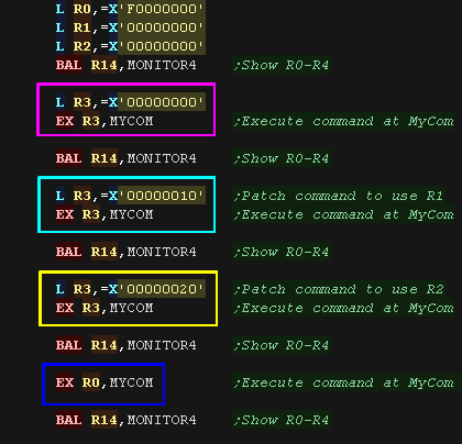  |
| Here are the results! Note the command at MyCom will not have been changed by any of these commands |
 |
| There may be times we want
to perform a conversion of a sequence of bytes via a lookup table. This could be useful for converting Ebdic to ascii, or preparing binary data for visual representation. TRanslate takes two addresses and one length in the form TR D1(L,B1),D2(B2). the address before the comma is the data to convert, the second parameter is the 'lookup table' Each if the L bytes in the destination D1(B1) is used as an offset in the lookup table D2(B2) and the replacement is placed back in D1(B1) Here we use TR to convert 8 bytes of MyData using MyLUT |
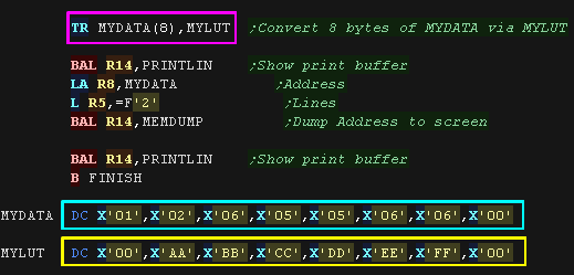 |
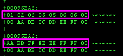
| Here are the results... The 8 bytes
were translated by the LUT. |
 |
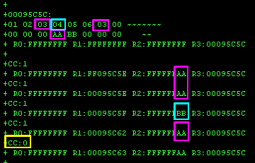
| TRanslate and Test is an odd command! Like TRanslate it uses a lookup table, however this command does not change data. It scans for a byte with a Lookup table entry of something other than 0. Even stranger, whatever registers we use, TRT uses R1 and R2 to store some of the results! If byte from the LUT!=0 a few things happen: 1. 24 LSBits of R1 set to the addr of the byte in src data 2. 8 LSbits of R2 are set to the nonzero LUT value 3. Execution then stops, even if L bytes were not processed. This command also sets the Condition Codes as follows : 0: All L bytes processed, all lookup bytes zero 1: Not all L bytes processed, A nonzero lookup byte was found 2: All L bytes processed, last byte was nonzero 3: Unused Here we use TRT several times First we scan for a single value with R3, Then we use R1 as the position, and repeatedly scan for values (as R1 is updated by TRT) |
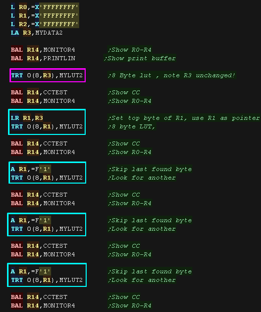 |
| We found '03' the first time
with R3 as the offset, Then the first time with R1 as the offset,
and a second time. We then found '04'.... finally we couldn't find another nonzero, so CC was set to 0 |
 |
|
Remember! The
IBM370 uses EBDIC for character numbering when showing decimal
to the screen, not the usual ASCII!... don't like it? Tough
luck! IBM didn't just use EBDIC to make our lives miserable, it's designed for easy entry on a punched card... AND to make our lives miserable! |
| Digit |
Code |
Sign |
Code |
| 0 | 0000 | + ascii |
1010 (0xA) |
| 1 | 0001 | - ascii |
1011 (0xB) |
| 2 | 0010 | + ebdic |
1100 (0xC) |
| 3 | 0011 | - ebdic |
1101 (0xD) |
| 4 | 0100 | + | 1110 (0xE) |
| 5 | 0101 | + | 1111 (0xF) |
| 6 | 0110 | ||
| 7 | 0111 | ||
| 8 | 1000 | ||
| 9 | 1001 |
Unpacked Binary coded decimal on IBM370 uses references to 'Zones' and 'Numerics'.... these sound complex, but simply refer to the high and low nibbles in each byte, For example:
$ZNZNZNZ or %ZZZZNNNN %ZZZZNNNN %ZZZZNNNN %ZZZZNNNN
For example, 'S' represents the Sign nibble in the following 7 digit examples: (Z=zone N=Numeric)
Zoned: $ZN ZN ZN ZN ZN ZN SN
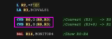
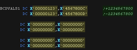
| Our normal 32 bit numbers are referred to as 'Binary'... the
Binary Coded Decimal values are called 'Decimal' We can convert a Decimal value in memory to a binary value in a register with CVB R1,D2(X2,B2) This will convert an 8 byte decimal value into a 32 bit binary. |
  |
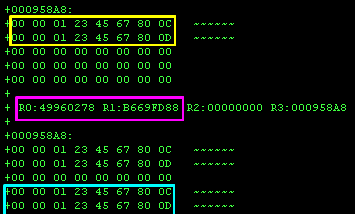
| We can convert a 'normal' binary value in a register to a
'Decimal' with CVD R1,D2(X2,B2) Here we convert the values in the registers back to to |
 |
| We converted the source Binary
into decimal, then back
into binary. |
 |
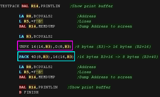
| The typical format for decimal on the IBM370 is 'Packed'
decimal, this is where each nibble contains a digit, so one byte
contains two digits. Unpacked decimal only stores a digit in the bottom nibble, this bottom nibble is known as the 'Numeric'. the top nibble is known as the 'Zone'... if the top nibble contains '0xF' (15), then the unpacked digit will be a valid EBDIC character for display. UNPK D1(L1,B1),D2(L2,B2) will UNPacK decimal, converting Packed -> Zoned We need to specify a packed source D2(B2) and it's length L2, and a destination D1(B1) and the destination length L1 We can Pack the data from zoned to packed data with PACK D1(L1,B1),D2(L2,B2) |
 |
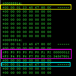
| Here is the result. We took the Source data, Unpacked it, then Packed it again! |
 |
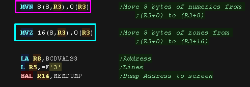
| As mentioned before, When working with Unpacked data the top
nibble is referred to as the 'Zone' (0xF for EBDIC) and the bottom
nibble is referred to as the 'Numeric' We have special commands to move with these 'Numerics' and 'Zones', but in fact they work with any data, not just valid Decimal. Here we use MVN D1(L,B1),D2(B2) to MoVe the Numerics (The bottom nibbles) We then use MVZ D1(L,B1),D2(B2) to MoVe the Zones (The top nibbles) |
 |
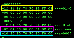
| Here is the result We took our source data, copied the numerics, then copied the zones. |
 |
| The IBM370 has a selection of common maths commands! The most simple of these are AP (Add Packed) and SP (Subtract Packed) |
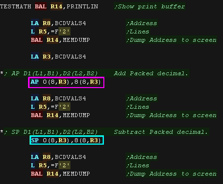 |
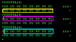
| We added our test value of +1, then we subtracted
it! |
 |
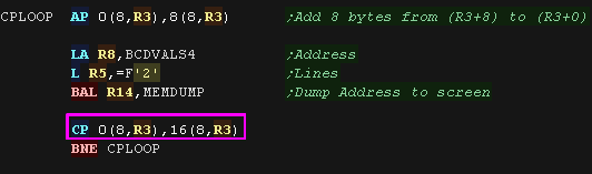
| We also have a compare command! CP -
Compare Packed This sets the Condition Codes as follows: 0: Both equal 1: D1(B1) lower 2: D1(B1) higher 3: Unused here we use CP and AP to form a loop waiting for 0(8,R3) to equal +2 |
 |
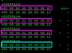
| +1 was added, until the value reached +2 |
 |
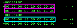
| If addition and subtraction doesn't impress you we also
have Multiplication of Packed values with MP D1(L1,B1),D2(L2,B2) - Multiply Packed! Note: L2 (the parameter length) must me shorter than L1 (the destination length) |
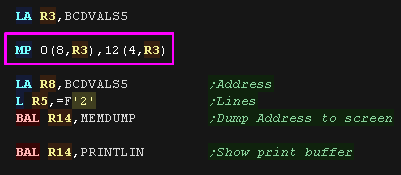 |
| The two values were
multiplied, and the result stored! |
 |
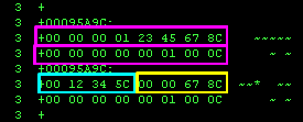
| We also have Division with: DP D1(L1,B1),D2(L2,B2) - Divide Packed decimal Once again L2 must be 8 or less & shorter than L1, and like the other divide commands we get a integer division result, and a remainder... unfortunately the format of the data stored at D1(B1) is a little confusing! The last L2 bytes in the L1 bytes at D1(B1) are remainder, The rest are the integer result (the top /first bytes at that address) |
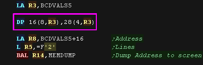 |
| Here is the result. The Parameters were divided L2 was 4, so the last 4 bytes are the remainder. L1 was 8, so the first 4 bytes are the result (L1-L2 = 8-4) |
 |
| There are a few 'rarer' Decimal maths commands, which are worth
knowing about, but you are less likey to need. The first is ZAP... it's nothing to do with rayguns, it stands for Zero Add Packed ZAP D1(L1,B1),D2(L2,B2) Actually it doesn't have much to do with addition either. it 'Adds' to zero, and the effect is 'Resizing' a packed decimal sequence from L2 bytes to L1 bytes |
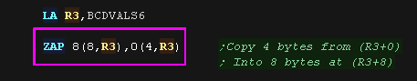 |
| The 4 byte decimal was
'expanded' into 8 bytes. |
 |
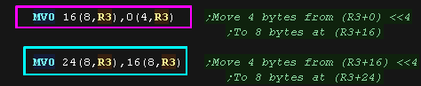
| If we want to bit shift we can use MVO - Move with offset: MVO D1(L1,B1),D2(L2,B2) This copies a sequence from the source to the destination, shifting it 4 bits left. We run this command twice! |
 |
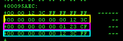
| We copied the source to the
first destination, shifted left
by 4. We then copied that again, shifted left another 4! |
 |
The IBM370 was a server designed for processing data, such as financial information, and it comes with two of the most complex and powerful commands I've seen in any assembling language... ED - EDit and EDMK -EDit and MarK
            ____123.45_______12,349.01 CR

            __1,000.00 CR____12,349.01___

            ______0.01 CR_________0.00___
     _dd,dsd.dd CRf
        dd,dsd.dd CR
Here we have three lines of tabulated accounting data, Symbols like commas are hidden by replacing them with spaces at first (Shown as underscores here for clarity), but need to be shown once the non-zero digits start.
The final digits, the '0.00' need to be shown whatever the total though. For accounting we will want to show some kind of negative marker, a minus - or in this case a 'CR' for credit.
This is exactly what the Edit command does. The Edit command uses a 'pattern' (Shown as the grey line in the example') which acts as a 'mask' for the result (similar to the PRINT USING command in basic). For clarity in the example show 'd' 's', and 'f' have been used, but these should be hex codes 0x20, 0x21 and 0x22 in the actual pattern, however all other characters are as they were provided to the code.
We provide the Pattern at address D1(B1), the Pattern length in L and a source packed Decimal sequence at D2(B2). The Pattern at D1(B1) is overwritten with the formatted sequence. The Decimal at D2(B2) is unchanged.
The first character in the sequence is the 'Spacer character' This will be used to replace zero digits in the rest of the sequence. The spacer is also used to replace sign characters when the sign of the number is positive, commas and anything else not to be shown.
|
Character |
In example |
purpose |
|---|---|---|
|
0x20 (DS) |
d |
Digit Select - Placeholder to be replaced with number |
|
0x21 (SOS) |
s |
Significance Start - Beginning of always shown digits (0.00) |
|
0x22 (FS) |
f |
Field Separator - Start a new field |
|
Anything |
|
Printed as is before decimals,
|
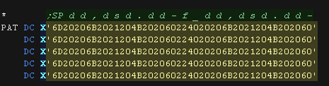
| Here we are defining a sequence of lines with a mask as follows: _dd,dsd.dd-f_dd,dsd.dd- This allocates enough width for 2 columns (fields) |
 |
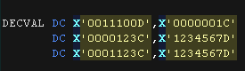
| Here are the decimal values we will 'format' |
 |
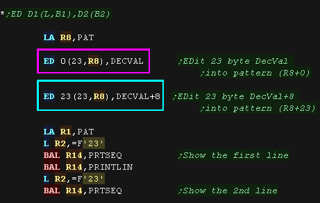
| Each of our lines is 23 bytes. Here we process two lines (2 values per line) using EDit. |
 |
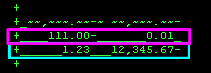
| Here are the results. We showed X'0011100D', X'0000001C', X'0000123C', X'1234567D'. Where the ',' or '-' wasn't needed it was replaced by _ (as it was the first char in the pattern) the 'Significance start' 's' 0x21 defined the start of the 'must show' digits the 'field separator' 'f' 0x22 in the middle of the sequence defined the start of the next value |
 |
Whatever registers we specified with the command, the main CPU register R1 is used to store the address of the character. Only the bottom 24 bits of R1 are changed, the top 8 bits of R1 are unchanged.
This is intended for later adding a movable currency symbol ($ etc) before the first digit. For Example:
    ___$123.45______

            _$1,000.00 CR___
As this command only tracks the first character inserted, it will not be effective if two fields are contained in the same line, as only the position for the first character would be held in R1.
| We're going to define a sub 'DoSym' which will insert a symbol IF EDMK got a character (we'll clear R1 to zero before running EDMK) | 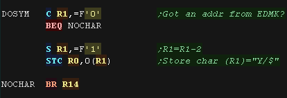 |
| here we use EDMK Three
times |
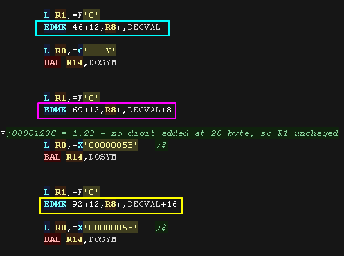 |
| Here are the results. Notice the second line has no $/Y - This is because all the digits were after the significance start 0x21 (s), R1 is only loaded with the address of the first INSERTED CHARACTER at a 'd' 0x20 field |
 |
| View Options |
| Default Dark |
| Simple (Hide this menu) |
| Print Mode (white background) |
| Top Menu |
| ***Main Menu*** |
| Youtube channel |
| Patreon |
| Introduction to Assembly (Basics for absolute beginners) |
| Amazon Affiliate Link |
| Forum |
| AkuSprite Editor |
| ChibiTracker |
| Dec/Bin/Hex/Oct/Ascii Table |
| Alt Tech |
| Archive.org |
| Bitchute |
| Odysee |
| Rumble |
| DailyMotion |
| Please note: I wlll upload more content to these alt platforms based on the views they bring in |
| 68000 Content |
| ***68000 Tutorial List*** |
Learn 68000 Assembly  |
| Hello World Series |
| Platform Specific Series |
| Simple Samples |
| Grime 68000 |
| 68000 Downloads |
| 68000 Cheatsheet |
| Sources.7z |
| DevTools kit |
| 68000 Platforms |
| Amiga 500 |
| Atari ST |
| Neo Geo |
| Sega Genesis / Mega Drive |
| Sinclair QL |
| X68000 (Sharp x68k) |
| 8086 Content |
| Learn 8086 Assembly |
| Platform Specific Series |
| Hello World Series |
| Simple Samples |
| 8086 Downloads |
| 8086 Cheatsheet |
| Sources.7z |
| DevTools kit |
| 8086 Platforms |
| Wonderswan |
| MsDos |
| ARM Content |
| Learn ARM Assembly |
| Learn ARM Thumb Assembly |
| Platform Specific Series |
| Hello World |
| Simple Samples |
| ARM Downloads |
| ARM Cheatsheet |
| Sources.7z |
| DevTools kit |
| ARM Platforms |
| Gameboy Advance |
| Nintendo DS |
| Risc Os |
| Risc-V Content |
| Learn Risc-V Assembly |
| Risc-V Downloads |
| Risc-V Cheatsheet |
| Sources.7z |
| DevTools kit |
| MIPS Content |
| Learn Risc-V Assembly |
| Platform Specific Series |
| Hello World |
| Simple Samples |
| MIPS Downloads |
| MIPS Cheatsheet |
| Sources.7z |
| DevTools kit |
| MIPS Platforms |
| Playstation |
| N64 |
| PDP-11 Content |
| Learn PDP-11 Assembly |
| Platform Specific Series |
| Simple Samples |
| PDP-11 Downloads |
| PDP-11 Cheatsheet |
| Sources.7z |
| DevTools kit |
| PDP-11 Platforms |
| PDP-11 |
| UKNC |
| TMS9900 Content |
| Learn TMS9900 Assembly |
| Platform Specific Series |
| Hello World |
| TMS9900 Downloads |
| TMS9900 Cheatsheet |
| Sources.7z |
| DevTools kit |
| TMS9900 Platforms |
| Ti 99 |
| 6809 Content |
| Learn 6809 Assembly |
| Learn 6309 Assembly |
| Platform Specific Series |
| Hello World Series |
| Simple Samples |
| 6809 Downloads |
| 6809/6309 Cheatsheet |
| Sources.7z |
| DevTools kit |
| 6809 Platforms |
| Dragon 32/Tandy Coco |
| Fujitsu FM7 |
| TRS-80 Coco 3 |
| Vectrex |
| 65816 Content |
| Learn 65816 Assembly |
| Hello World |
| Simple Samples |
| 65816 Downloads |
| 65816 Cheatsheet |
| Sources.7z |
| DevTools kit |
| 65816 Platforms |
| SNES |
| eZ80 Content |
| Learn eZ80 Assembly |
| Platform Specific Series |
| eZ80 Downloads |
| eZ80 Cheatsheet |
| Sources.7z |
| DevTools kit |
| eZ80 Platforms |
| Ti84 PCE |
| IBM370 Content |
| Learn IBM370 Assembly |
| Simple Samples |
| IBM370 Downloads |
| IBM370 Cheatsheet |
| Sources.7z |
| DevTools kit |
| Super-H Content |
| Learn SH2 Assembly |
| Hello World Series |
| Simple Samples |
| SH2 Downloads |
| SH2 Cheatsheet |
| Sources.7z |
| DevTools kit |
| SH2 Platforms |
| 32x |
| Saturn |
| PowerPC Content |
| Learn PowerPC Assembly |
| Hello World Series |
| Simple Samples |
| PowerPC Downloads |
| PowerPC Cheatsheet |
| Sources.7z |
| DevTools kit |
| PowerPC Platforms |
| Gamecube |
| Work in Progress |
| ChibiAndroids |
| Misc bits |
| Ruby programming |
Buy my Assembly programming book
on Amazon in Print or Kindle!


Available worldwide!
Search 'ChibiAkumas' on
your local Amazon website!
Click here for more info!


Buy my Assembly programming book
on Amazon in Print or Kindle!
Available worldwide!
Search 'ChibiAkumas' on
your local Amazon website!
Click here for more info!
Buy my Assembly programming book
on Amazon in Print or Kindle!
Available worldwide!
Search 'ChibiAkumas' on
your local Amazon website!
Click here for more info!
Buy my Assembly programming book
on Amazon in Print or Kindle!
Available worldwide!
Search 'ChibiAkumas' on
your local Amazon website!
Click here for more info!
Buy my Assembly programming book
on Amazon in Print or Kindle!
Available worldwide!
Search 'ChibiAkumas' on
your local Amazon website!
Click here for more info!
Buy my Assembly programming book
on Amazon in Print or Kindle!
Available worldwide!
Search 'ChibiAkumas' on
your local Amazon website!
Click here for more info!
Buy my Assembly programming book
on Amazon in Print or Kindle!
Available worldwide!
Search 'ChibiAkumas' on
your local Amazon website!
Click here for more info!
Buy my Assembly programming book
on Amazon in Print or Kindle!
Available worldwide!
Search 'ChibiAkumas' on
your local Amazon website!
Click here for more info!
Buy my Assembly programming book
on Amazon in Print or Kindle!
Available worldwide!
Search 'ChibiAkumas' on
your local Amazon website!
Click here for more info!
Buy my Assembly programming book
on Amazon in Print or Kindle!
Available worldwide!
Search 'ChibiAkumas' on
your local Amazon website!
Click here for more info!