Z80 Assembly programming for the Camputers Lynx


The Camputers Lynx is an early Z80 computer... while it's not very impressive compared to a late Z80 system like the CPC or the Sam Coupe, the Lynx came out in 1983 .

While it's 48k is relatively modest it does have one big advantage... it uses a 3 bitplaned screen - allowing 8 colors at 256x252 pixels... and even offers 2 screen buffers for the 'green' color channel within the built in 32k Vram

Due to its early release, it's hardware is a little odd, but it offers some decent graphics and it's unusual hardware setup makes it quite a curiosity... lets take a look!

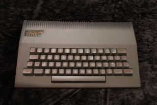


There were various releases of the Lynx, with different amounts of memory, 48k,96k and 128k

Cpu 4 mhz Z80
Ram 48k (32k is Vram)
Resolution 256x252
Colors 8
Sound chip Beeper
Camputers Lynx
ChibiAkumas Tutorials
    Lesson H6 - Hello World on the Camputers Lynx

Lesson P33 - Bitmap Graphics on the Camputers Lynx

Lesson P34 - Sound and Keyboard on the Camputers Lynx

Lesson P37 - Playing Digital Sound with WAV on the Sam Coupe, Camputers Lynx and ZX Spectrum


Documentation

Unfortunately, there is very little documetation on the Camputers Lynx... fortunately the' Lynx User' newsletter covered everything pretty clearly... you can get it here:
LynxUser on Github

The Mysteries of the LynxAddress bus!
The Lynx does not use all the bits of the address bus for accessing memory... I guess they figured that as the machine had only 16k, that using all the 'bits' of the memory address were excessive... two bits are unused... and that means certain areas are 'Mirrored'... so the same bank appears in multiple places!

Lets take a look at which of the 16 bits are ignored! ... in the chart below, bits marked X are ignored, and bits marked 1 work normally.
 
 F  E  D  C  B  A  9  8  7  6  5  4  3  2  1  0
X 1 X 1 1 1 1 1 1 1 1 1 1 1 1 1

What's the effect of this? well, because on the 48k lynx 32k is VRAM... this just leaves 2x 8k banks of ram... and each of these 2 banks appear in 4 different positions!

8k ram bank Seen at Addresses
A &0000-&1FFF
&2000-&3FFF
&8000-&9FFF
&A000-&BFFF
B &4000-&5FFF
&6000-&7FFF
&C000-&DFFF
&E000-&FFFF

The extra 4 Video Ram banks are 8k each... One for Red, Green and Blue... and an 'alternate green' which can be paged in

There is also 24k rom which can be paged in... these appear 'Above' the ram mentioned previously... and these do not apply to the rom banking

Lets take a look at the bank switching options

Bank  &0000 -
&1FFF
 &2000 -
&3FFF
 &4000 -
&5FFF
 &6000 -
&7FFF
 &8000 -
&9FFF
 &A000 -
&BFFF
 &C000 -
&DFFF
 &E000 -
&FFFF
Ram
 amount
(128k+)
 Purpose
0 A /
Rom1
A /
Rom2
B /
4kRom
B A A B B /
ExtRom
20K  Accessing
Rom
1 Ram
Ram
Ram
Ram B
Ram A Ram Ram
Ram
64K Accessing 
Ram
2 A A B B A A /
Blue
B /
Red
B 16K Accessing
Red/Blue Vram
3 A A B B A A /
 AltGreen
B /
Green
B 16K Accessing
Green Vram
4 Off Board Expansion

BankSwitching

The bits of the byte written to port &FFFF will control which banks are accessed ... the combination of the bits selected will define the resultant memory accessed by the Z80

Port &FFFF
Bits
7 6 5 4 3 2 1 0
Meaning Read
Bank 4
Read
Bank 2 / 3
Read
Bank 1
Read
Bank 0
Write
Bank 4
Write
Bank 3
Write
Bank 2
Write
Bank 1
Purpose
Read
Vram

Read
ROM

Write Green /
AltGreen Vram
Write
Red/Blue Vram
Write
16k RAM

VRAM Access

The Video Ram is accessible via the Z80 addressable range, but we nee to page in the correct bank AND set the right video option...
This is done with Port &0080

Port &0080
Bits
7 6 5 4 3 2 1 0
Meaning     0     VSYNC CPU 
Access
Show Green
/Altgreen
Lock
Bank3
Lock
Bank2
    0         0    
Purpose
Wait for
next redraw
Allow Vram Pageflipping
1=Alt 
Write Red /
Blue Vram
Write Green /
AltGreen Vram


To write to the banks, we need to enable CPU access... and Lock the bank we DONT want to write to.

If we do not wait for redraw (with bit 6) then screen distortion will occur (black pixels) as we cannot write to VRAM while the CRTC beam is drawing the screen.


Note... you cannot Read and Write to a bank at the same time... so you can't copy one area of the screen to another to soft-scroll!

Also it is virtually impossible to READ VRAM from code not in ROM... this is because the Lynx's limited address bus means it can only address 16k, and when READ is set to the VRAM the normal ram disappears!... this means the running code would have to be in VRAM (thus visible)  which in most cases is not practical.

See the table below for the correct settings depending what you want to do
  Mode   Color Out
 (&FFFF)
Out
 (&0080) 
  Address  
Range
Read Red &60 &28 &C000-&DFFF
Blue &60 &28 &A000-&BFFF
Green &60 &24 &C000-&DFFF
 AltGreen &60 &24 &A000-&BFFF


Write Red &03 &28 &C000-&DFFF
Blue &03 &28 &A000-&BFFF
Green &05 &24 &C000-&DFFF
 AltGreen &05 &24 &A000-&BFFF


OFF
&0  &0

To speed things up if we just want to do black and white, We can take advantage of the Lynx write banking to write to both Blue+AltGreen, or Red+Green at the same time .... note it is not possible to write to Red+Green+Blue at the same time
  Mode   Color Out
 (&FFFF)
Out
 (&0080) 
  Address  
Range
Write Red+Green &07 &20 &C000-&DFFF
Blue+AltGreen &07 &20 &A000-&BFFF

Screen corruption due to shared Vram
Note: Because of the limited address bus, writing to the areas B or A in &8000-&9F80 or &6000-&7F80 will affect the matching screen ram... meaning random pixels may light up!
Even worse, it seems these writes do not affect the internal ram even if bit 0 of &FFFF is set... meaning the write is 'consumed' by the screen
Because the stack is at &8FFF, it seems to be outside the visible screen on the PALE emulator... but inside the visible screen on JYNX !?!
Therefore, ideally, we should avoid using the stack too!

Simple Memory Map
The bankswitching options can make things tricky... but here is a 'simple' memory map of what you can expect to see on a 48k Lynx

Address Purpose
&0000 ROM
&6000 Basic Ram
&6307 Basic Stack
&6C00 Free Ram
&9FFF Stack pointer
&A000 VRAM (Blue / AltGreen)
&C000 VRAM (Red / Green)
&E000 Unused
&FFFF End of ram

Lynx TAP file format
As the LYNX has no cartridges, our best way of getting data from our assembler to the Lynx is to make a TAP file...
Creating a valid TAP file requires some byte calculations, but is not too hard... here is the format of the TAP file
FilePos Bytes Suggestion Purpose
0 8 �NONAME� filename
8 1 M file type (M=Machine code)
9 2 &100 Program length
11 2 &6500 Load Point (LH � little endian)
13 len ? Program Code
13+len 2 &1313 Check digit (sum of program code) � twice!
15+len 2 &6500 Execute point
17+len 1 &65 High byte of Execute point

Lynx Keymap
The keyboard responds to all ports with a bitmask of %****XXXX 10***00* ... where XXXX is one of the ports below


7 6 5 4 3 2 1 0
BC=&0080 %0000  
Shift Escape Down Up ShiftLK

1
BC=&0180 %0001

C D X E 4 3
BC=&0280 %0010
Control A S Z W Q 2
BC=&0380 %0011

F G V T R 5
BC=&0480 %0100

B N Space H Y 6
BC=&0580 %0101

J
M U 8 7
BC=&0680 %0110

K ,
O I 9
BC=&0780 %0111

;
. L P 0
BC=&0880 %1000

:
/ I @ -
BC=&0980 %1001

Right
Return Left ] Delete


Lynx Sound
The Lynx uses 'Beeper sound' almost identical to the ZX Spectrum - however unlike the spectrum beeper, the Camputers Lynx has the ability to set volume level.

Sound is controlled on the lynx by port &0084 - or any port that matches the bitmask %********10***10*

Bits  7  6  5  4  3  2  1  0
Detail  0*  - Volume
* Bit 7 MUST be zero