
Learn Multi
platform Z80 Assembly Programming... With
Vampires!
Platform Specific Lessons
Platform Specific Lessons
<- Back to the Main
Contents & Basic Z80 Assembly Lessons
Platform Specific Series - Lets learn how the hardware of the systems work, so we can get it to do what we want... Covers Amsrad CPC,MSX,ZX Spectrum, TI-83,Enterprise 128/64 and Sam Coupe!
Defining a Sprite
What's the effect of this? well, because on the 48k lynx 32k is VRAM... this just leaves 2x 8k banks of ram... and each of these 2 banks appear in 4 different positions!
The extra 4 Video Ram banks are 8k each... One for Red, Green and Blue... and an 'alternate green' which can be paged in
There is also 24k ROM which can be paged in... these appear 'Above' the ram mentioned previously... and these do not apply to the rom banking
Lets take a look at the bank switching options
BankSwitching
The bits of the byte written to port &FFFF will control which banks are accessed ... the combination of the bits selected will define the resultant memory accessed by the Z80
VRAM Access
The Video Ram is accessible via the Z80 addressable range, but we need to page in the correct bank AND set the right video option...
This is done with Port &0080
To write to the banks, we need to enable CPU access... and Lock the bank we DONT want to write to.
Note... you cannot Read and Write to a bank at the same time... so you can't copy one area of the screen to another to soft-scroll!
Also it is virtually impossible to READ VRAM from code not in ROM... this is because the Lynx's limited address bus means it can only address 16k, and when READ is set to the VRAM the normal ram disappears!... this means the running code would have to be in VRAM (thus visible) which in most cases is impractical!
See the table below for the correct settings depending what you want to do
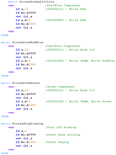
To speed things up if we just want to do black and white, We can take advantage of the Lynx write banking to write to both Blue+AltGreen, or Red+Green at the same time .... note it is not possible to write to Red+Green+Blue at the same time
Screen corruption due to shared Vram
Note: Because of the limited address bus, writing to the areas B or A in &8000-&9F80 or &6000-&7F80 will affect the matching screen ram... meaning random pixels may light up!
Even worse, it seems these writes do not affect the internal ram even if bit 0 of &FFFF is set... meaning the write is 'consumed' by the screen
Because the stack is at &8FFF, it seems to be outside the visible screen on the PALE emulator... but inside the visible screen on JYNX !?!
Therefore, ideally, we should avoid using the stack too!
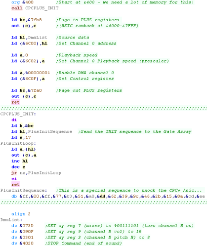
The CPC+ has three DMA 'Channels'... each reads in one 2-byte (one command) word every 'tick' at a frequency of 15khz... there are 3 channels to allow all 3 AY channels to be changed at the same time on a 'tick'... however it is perfectly possible to use DMA channel 0 to change AY channel 1(B) or 2(C)
Every channel has a DMA address and a Prescaler
The DMA address is a pair of bytes which point to the sound data - which must be in the MAIN 64k of memory - it cannot be in ROM or 128k ram. it must also be on an EVEN BYTE - so put an ALIGN 2 before the data
There is a 'Prescaler' this affects the PAUSE command (and only that command) - to allow for the playback speed to be reduced....
Finally, there is a Control/Status register... Writing 1 to this will turn a channels DMA on (starting the data transfer)... This can be read during your interrupt handler to see what has caused an interrupt - Bit 7=1 means Vblank just occurred...Bits 6-4=1 mean that one of the DMA channels caused an interrupt - this can be used to 'alert' when the playback of a sample has ended so another sample can be queued.
A complete example!
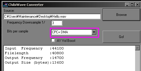
Converting a WAV file for DMA via ChibiWave converter
Double buffering
Double buffering means using two screen buffers - one which is being shown.... and another being drawn.... the advantage is this means we can build up our screen over time without visible flickering, the disadvantage is we need 32k of ram to hold 2 screens.!
To set the visible screen buffer we need to change PP in register &0C... writing 48 will set the visible screen to &C000 - writing 16 will set it to &4000 and 32 will set it to &8000...
Many games that use double buffering will set the screen to &4000... ChibiAkumas used &8000 so that the swappable bank at &4000-&7FFF - but this meant the AmsDOS settings at around &A600 were lost...
If you wanted to use memory &0000 for the screen, we'd either need to never turn on interrupts, or use IM2 - because IM1 uses &0038 as the interrupt call.
Using and Testing the registers!
Continue to Page 5
Back to Page 3
Platform Specific Series - Lets learn how the hardware of the systems work, so we can get it to do what we want... Covers Amsrad CPC,MSX,ZX Spectrum, TI-83,Enterprise 128/64 and Sam Coupe!
   |
Lesson
P31
-
Hardware Sprites on the Master System / Game Gear and
MSX1! SMS /GG sprites are much easier, so we'll take a look at them, and also look at the MSX1 as a bonus! |
 |
 |
 |
  |
Hardware Sprites on the SMS / GG |
| The SMS/GG memory supports up to
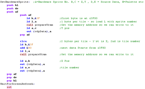
64 sprites, There are 3 memory bytes for each hardware sprite, but they are not consecutive! Look at sprite 0 - shown in black... it's X co-ordinate is at &3F00 ... it's Y co-ordinate is at &3F80... it's Sprite Number is at &3F81 Sprite Numbers can come from memory address &2000, or &0000 (The Tile Patterns) depending on the setting of register &06... we'll be using the Tile patterns for simplicity in our example! It's important to note that the sprites ALWAYS use colors 16-31 Unfortunately there is no way to flip sprites, so we will need a pair of sprites to allow a player sprite to turn around! |
Sprite Attribute Table (In VRAM)
|
| The SMS
sprites can be read from pattern data, or from a separate
bank... in the same ways, the Tilemap can use the same colors
as the sprites, or a separate palette... These examples will use the simplest option - sharing both between sprites and tilemap - of course, if you're creating a big game, you'll want to separate them to make your game look the best! |
 |
 |
Hardware Sprites on the MSX |
|
On the MSX the system is capable
of 32 sprites onscreen... but just 4 can be on the same
line... The sprites are 2 color.
Sprite patterns are held at
&3800 - there is enough ram for 64 sprite patterns
The sprites patterns can be 8x8
or 16x16 and can be 'doublesize' 2x scaled , but this is
declared at the screen level in register 0... so you cannot
have some sprites 8x8 regular, and others 16x16 doublesize
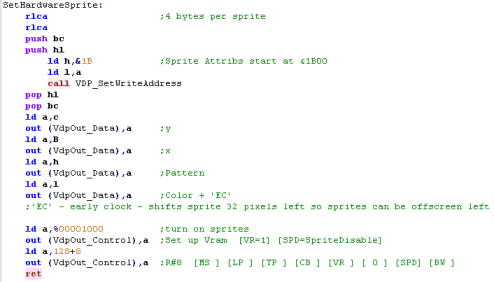
Each Sprite is defined by 4 concecutive bytes in the sprite attribute table (usually at &1B00) containing a Y and X co-ordinate, a Pattern number (corresponding to a tile in the sprite data at &3800) in 16x16 mode patterns will be 4x size, and the tilenumber will only use the top 6 bits %111111-- ... the bottom two will be ignored when X,Y= 0,0 the sprite will be in the top corner of the drawable area, but will be completely visible. if you want to clip The Y lines of the sprite, use Y positions of 255 or less - this is effectively -1 or lower Because the screen is 256 pixels wide, we cannot do this for X Co-ordinates - instead we use the top bit of the 'Color' attribute of each sprite (only the bottom nibble defines color)... When the top bit is 1 - the sprite will be shifted 32 pixels left, so 0,0 will now be -32,0 The order of the 8x8 chunks in 16x16 sprite mode is possibly a little odd...imagine 4 8x8 blocks in a 16x16 sprite... they need to be in the following order:
|
Sprite Attributes:
|
|||||||||||||||||||||||||||||||||||||||||||||||||||||||||||||||||||||||||||||||||||||||||||||||||||||||||||||||||||||||||||||||||||||||||||||||||||||||||||||||||||||||||||||||||||||||||||||||||||||||||||||||||||||
| We need to actually turn on
sprites, by setting SPD to 0 in Register 8... it's important to
notice that this will make the MSX graphics slightly slower Register 1 controls the size and scale of the sprites, so can be used for 16x16 or doublesize sprites. |
|
 |
The MSX 2 is
capable of much more powerful sprites, and sprites can be
bit-combined to allow a lot of colors! - and that's just
hardware sprites, but hardware sprites slow down the hardware
by about 20% - and are still quite limited Chibiakumas uses software sprites using 'area copying' VDP commands - meaning no limit to the number of sprites onscreen - just a reduction in speed! |
ASIC Ram registers that define CPC+
Sprites
| Like most CPC+ features, Sprites are set and altered by
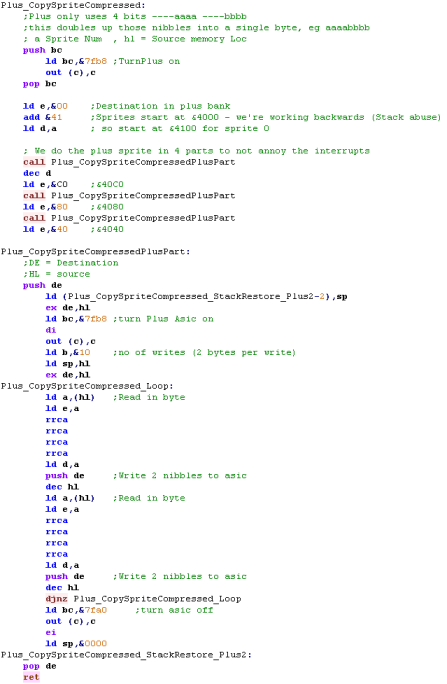
writing to ASIC ram after turning on Plus features, We've discussed how to do this before in the lesson on CPC+ Palettes Each sprite is 16x16 making 128 bytes... but the definitions only use the bottom nibble of each address (The top nibble of the sprite data registers cannot store data!), so each sprite is defined by 256 bytes of bitmap data. as well as bitmap data, there is an address storing the X and Y co-ordinate - and a 4 bit 'Magnification', 2 width bits and 2 height bits A magnification of 0 is a disabled sprite, a magnification of 1x1 is a 'Mode 2' sized pixel sprite... 2x1 is 'Mode 1'... and so on
So 'Resolution' setting of 9 will be a normal Mode 1 sized sprite CPC+ sprites are always 16 color, and use an 'extra' 16 colors to the normal palette... these palette definitions are held in the range &6422-&643F |
|
||||||||||||||||||||||||||||||||||||||||||||||||||||||||||||||||||||||||||||||||||||||||||||||||||||||||||||||||
 |
If you don't know how
to turn on PLUS features, see the CPC+ Palette lesson of these
tutorials.... Also, just remember the ASIC ram uses the area &4000-&7FFF , so your program code and sprite data have to be somewhere else! |
Defining a Sprite
| CPC+ Sprites
have a LOT of data, and we can't just change a pointer to
change the 'image' of a sprite... This means it may be slow to
animate them - at least compared to other systems with
hardware sprites... That said, the CPC+ sprites are big and colorful compared to other 8 bit systems! |
 |
Positioning a Sprite
Using our routines!
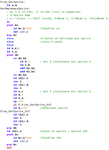
| Now our sprite has an image, we
need to position it on the screen, and give it a scale! If we want our Sprite to be sized with mode 1 pixels, we need to set it's scale to '9' To allow a single byte to define an X position, the X co-ordinate is defined in Mode 0 pixels, however you can change this if you want better definition.. Negative numbers can be used to clip a sprite to have it go off the Top/Left of the screen It is not possible to have a sprite in the border areas of the screen - the sprites are drawn in the normal bitmap area of the screen. |
 |
Using our routines!
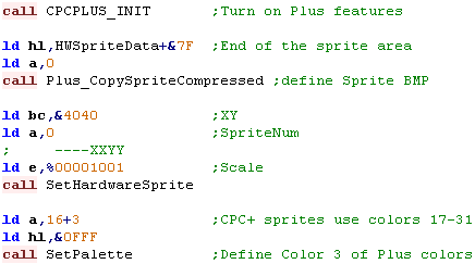
| Now we have our routines to do
the work, we need to use them! To start we need to turn on the plus features... Then we need to load in the bitmap data - we add 127 to the source address, because our code works BACKWARDS from the last byte of the sprite... Now we set a position and scale of our sprite - remember the scale cannot be 0 or it will be disabled. Finally, we set the color, the sample sprite only uses color 3, so that's all we'll set! |
 |
| The sprite will be drawn to the screen! |   |
| Want
more
than 16 sprites? Well, it's possible if you're REALLY clever
- you can re-position the sprites while the screen is
drawing, and you will effectively see them twice... in
ChibiAkumas 2 player mode the Heart+Scroll sprites were
re-positioned midscreen - so all 12 sprites were actually
just 6! Unfortunately, it's so much work to change the bitmap data, it's not possible to use a different sprite bitmap with this method, so you'll have to be clever in your sprite use! |
 |
The
Mysteries
of the LynxAddress bus!
The Lynx does not use all the bits of the address bus for accessing memory... I guess they figured that as the machine had only 16k, that using all the 'bits' of the memory address were excessive... two bits are unused... and that means certain areas are 'Mirrored'... so the same bank appears in multiple places!
Lets take a look at which of the 16 bits are ignored! ... in the chart below, bits marked X are ignored, and bits marked 1 work normally.
| F | E | D | C | B | A | 9 | 8 | 7 | 6 | 5 | 4 | 3 | 2 | 1 | 0 |
| X | 1 | X | 1 | 1 | 1 | 1 | 1 | 1 | 1 | 1 | 1 | 1 | 1 | 1 | 1 |
What's the effect of this? well, because on the 48k lynx 32k is VRAM... this just leaves 2x 8k banks of ram... and each of these 2 banks appear in 4 different positions!
| 8k ram bank | Seen at Addresses |
| A | &0000-&1FFF &2000-&3FFF &8000-&9FFF &A000-&BFFF |
| B | &4000-&5FFF &6000-&7FFF &C000-&DFFF &E000-&FFFF |
The extra 4 Video Ram banks are 8k each... One for Red, Green and Blue... and an 'alternate green' which can be paged in
There is also 24k ROM which can be paged in... these appear 'Above' the ram mentioned previously... and these do not apply to the rom banking
Lets take a look at the bank switching options
| Bank | &0000
-
&1FFF |
&2000
-
&3FFF |
&4000
-
&5FFF |
&6000
-
&7FFF |
&8000
-
&9FFF |
&A000
-
&BFFF |
&C000
-
&DFFF |
&E000
-
&FFFF |
Ram amount (128k+) |
Purpose |
| 0 | A
/ Rom1 |
A
/ Rom2 |
B
/ 4kRom |
B | A | A | B | B / ExtRom |
20K | Accessing Rom |
| 1 | Ram |
Ram |
Ram |
Ram B |
Ram A | Ram | Ram |
Ram |
64K | Accessing Ram |
| 2 | A | A | B | B | A | A / Blue |
B / Red |
B | 16K | Accessing Red/Blue Vram |
| 3 | A | A | B | B | A | A / AltGreen |
B / Green |
B | 16K | Accessing Green Vram |
| 4 | Off Board Expansion | |||||||||
BankSwitching
The bits of the byte written to port &FFFF will control which banks are accessed ... the combination of the bits selected will define the resultant memory accessed by the Z80
| Port
&FFFF
Bits |
7 | 6 | 5 | 4 | 3 | 2 | 1 | 0 |
| Meaning | Read Bank 4 |
Read Bank 2 / 3 |
Read Bank 1 |
Read Bank 0 |
Write Bank 4 |
Write Bank 3 |
Write Bank 2 |
Write Bank 1 |
| Purpose | Read Vram |
Read ROM |
Write Green / AltGreen Vram |
Write Red/Blue Vram |
Write 16k RAM |
VRAM Access
The Video Ram is accessible via the Z80 addressable range, but we need to page in the correct bank AND set the right video option...
This is done with Port &0080
| Port
&0080 Bits |
7 | 6 | 5 | 4 | 3 | 2 | 1 | 0 |
| Meaning | 0 | VSYNC | CPU Access |
Show Green /Altgreen |
Lock Bank3 |
Lock Bank2 |
0 | 0 |
| Purpose | Wait for next redraw |
Allow Vram Access |
Pageflipping 1=Alt |
Write Red / Blue Vram |
Write Green / AltGreen Vram |
To write to the banks, we need to enable CPU access... and Lock the bank we DONT want to write to.
Note... you cannot Read and Write to a bank at the same time... so you can't copy one area of the screen to another to soft-scroll!
Also it is virtually impossible to READ VRAM from code not in ROM... this is because the Lynx's limited address bus means it can only address 16k, and when READ is set to the VRAM the normal ram disappears!... this means the running code would have to be in VRAM (thus visible) which in most cases is impractical!
See the table below for the correct settings depending what you want to do
| Mode | Color | Out
(&FFFF) |
Out
(&0080) |
Address
Range |
| Read | Red | &60 | &28 | &C000-&DFFF |
| Blue | &60 | &28 | &A000-&BFFF | |
| Green | &60 | &24 | &C000-&DFFF | |
| AltGreen | &60 | &24 | &A000-&BFFF | |
| Write | Red | &03 | &28 | &C000-&DFFF |
| Blue | &03 | &28 | &A000-&BFFF | |
| Green | &05 | &24 | &C000-&DFFF | |
| AltGreen | &05 | &24 | &A000-&BFFF | |
| OFF | &0 | &0 |
To speed things up if we just want to do black and white, We can take advantage of the Lynx write banking to write to both Blue+AltGreen, or Red+Green at the same time .... note it is not possible to write to Red+Green+Blue at the same time
| Mode | Color | Out
(&FFFF) |
Out
(&0080) |
Address
Range |
| Write | Red+Green | &07 | &20 | &C000-&DFFF |
| Blue+AltGreen | &07 | &20 | &A000-&BFFF |
Screen corruption due to shared Vram
Note: Because of the limited address bus, writing to the areas B or A in &8000-&9F80 or &6000-&7F80 will affect the matching screen ram... meaning random pixels may light up!
Even worse, it seems these writes do not affect the internal ram even if bit 0 of &FFFF is set... meaning the write is 'consumed' by the screen
Because the stack is at &8FFF, it seems to be outside the visible screen on the PALE emulator... but inside the visible screen on JYNX !?!
Therefore, ideally, we should avoid using the stack too!
Paging
in
the VRAM
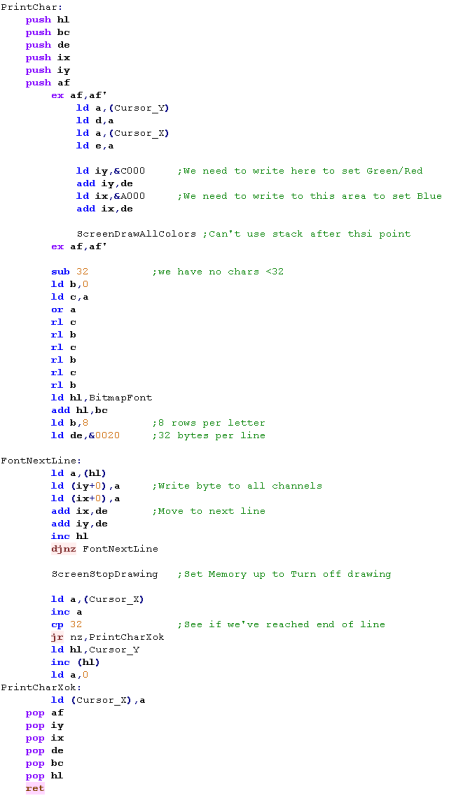
Printing
Characters
to the screen
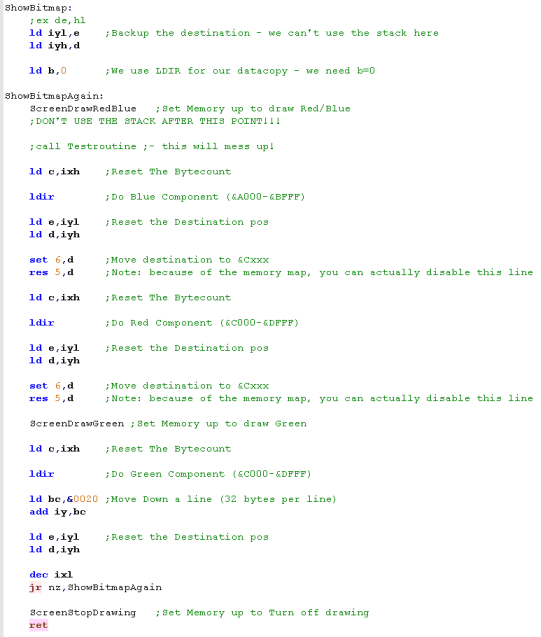
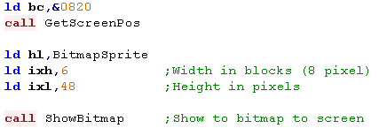
Drawing a bitmap to the screen
| Bear
in mind that while this writes to RED, GREEN and BLUE - it
also writes to ALTGREEN Altgreen isn't used by the visible screen in this example, but depending on how you're using the screen and memory, that could be a problem for you?! |
 |
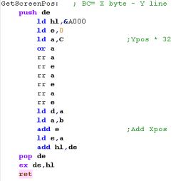
Get
Screen position
Drawing a bitmap to the screen
 |
This is
just an example of the kind of code you can use - depending
on your exact requirements, you should modify this to do
what you need.. For example the Grime Z80 port for the Lynx uses Tilemap code designed to work in 8x8 blocks, which is designed to work in the best way for one byte width blocks. |
Reading the Keyboard
| Like most Z80 computers, the Lynx
keyboard uses a set of ports, which represent 'rows' of the
keyboard, and each These 'rows' are relating to the electrical membrane, not keys as they appear, The keyboard responds to all ports with a bitmask of %****XXXX 10***00* ... where XXXX is one of the ports shown In this data, a key will be 1 if it is UP , or 0 if it's pressed down |
|
|||||||||||||||||||||||||||||||||||||||||||||||||||||||||||||||||||||||||||||||||||||||||||||||||||
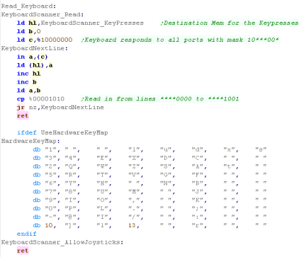
| In practical terms, this means we
set C to 128, and B to 0... then INC B until we get
to %00001010 This allows us to read in the raw bit data from the keyboard... we can then use the existing Multiplatform Code (Click Here) to convert raw data to letter keys (if we want) |
 |
The Beeper Speaker
Wave files and what we need for 8 bit machines
Creating a 16 bit wave file
Converting a wave file for playing on an 8 bit
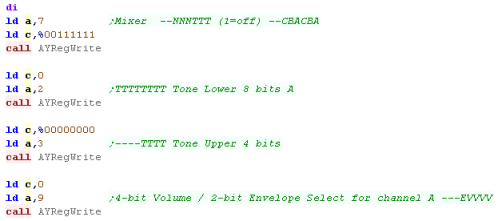
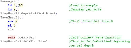
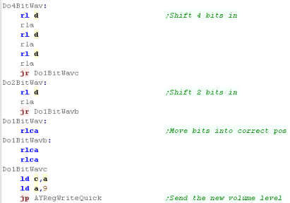
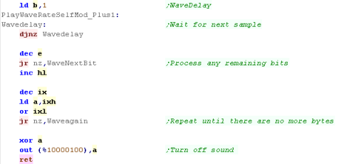
Wave Playback on the AY
| A beeper is a crude system, where we can define 'blips' of
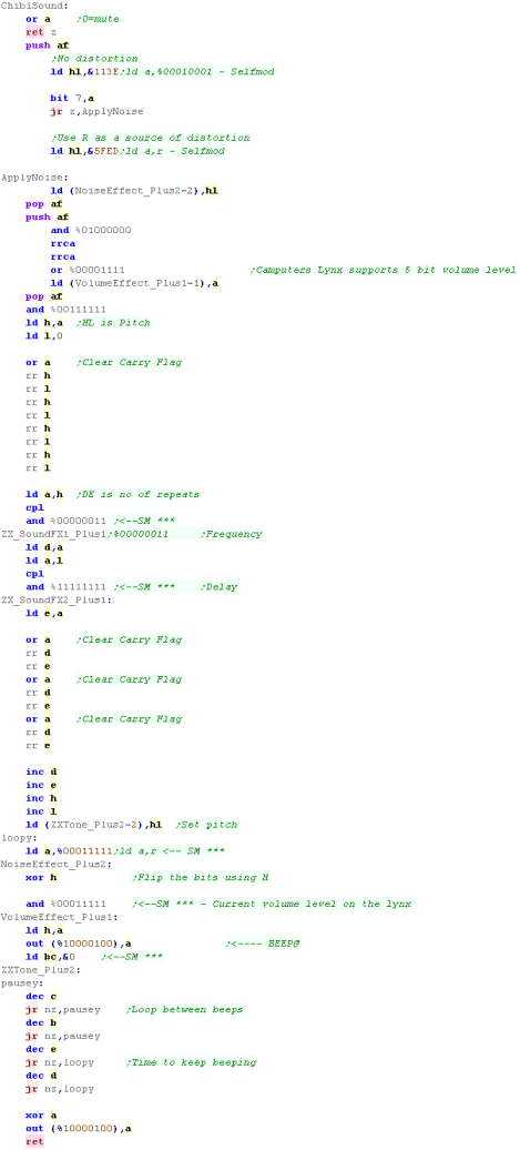
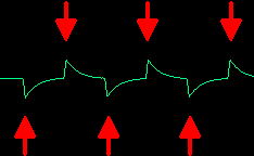
sound to make up a tone By altering the time between these 'blips' we can affect the pitch of the resulting tone!... the upside is we can make a good range of tones... the downside is, we'll pretty much have to use all our CPU power calculating the delay between the 'blips' re-sounding the blips... unlike the ZX Spectrum, however the Lynx can set volume levels using 6 bits Sound is controlled on the lynx by port &0084 - or any port that matches the bitmask %********10***10*
This means, unlike the other options, sound will not play during normal operation... so background music will be pretty much impossible If we want to make a distorted noise, that's pretty easy too... all we need to do is 'randomly' skip some of the 'blips'... the tone will sound rough and distorted as a result! |
 |
||||||||||||||||||
 |
Really, we're having
to create the waveform ourselves here by creating high and low
peaks... it's a real pain to do, but if you're very clever you
can do some impressive stuff! There is some sourcecode online for some ZX Spectrum 'music players' online that can play 'proper' multi-channel music using the beeper speaker if you really want to push beeper systems to the max! |
Wave files and what we need for 8 bit machines
| Most WAV files these days will be 16 bit - these will be
Signed, and will end up representing a wave with values from
32768 to -32768 - with silence being Zero. When we play the wave file on an 8 Bit sytem, we do so by adjusting the 'Volume' of the channel to match the wave, this will recreate the waveform, and the sound! BUT no 8 bit system has a 16 bit volume level... and memory is limited! A system like the AY has a 4 bit volume level - so we can 'pack' our wave data into two samples per byte... but we need to convert the 16 bit values to 4 bit unsigned ones.. you can see how the wave is represented by numbers in each bit option in the diagram to the right: |
A wave file, and how it's range is represented in different
bits per sample: |
Creating a 16 bit wave file
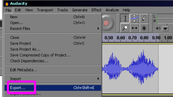
 |
The
ChibiWave converter supports MONO only, if the file is
stereo, the LEFT channel will be used... files MUST be
SIGNED 16 bit, but can be 22050 hz or lower... but if you
have trouble, make sure your input file is 44100 hz, MONO
and 16 bit as shown above! |
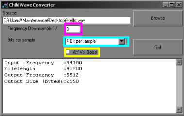
Converting a wave file for playing on an 8 bit
| There's
no reason you can't do 3 bits per sample too, but it's not
supported in these tutorials... It should also be noted that the code here is a 'one size fits all' solution, if you only need 4 bits per sample, you could modify it and write something far better! |
 |
Wave Playback on the AY
 |
On some
AY systems, It's possible to play multiple samples at
different volumes to increase the bits per sample from 4 to
8 or more... Unfortunately the Author of these tutorials is
to stupid to make it work... so if you want to look into it
check out this
site here |
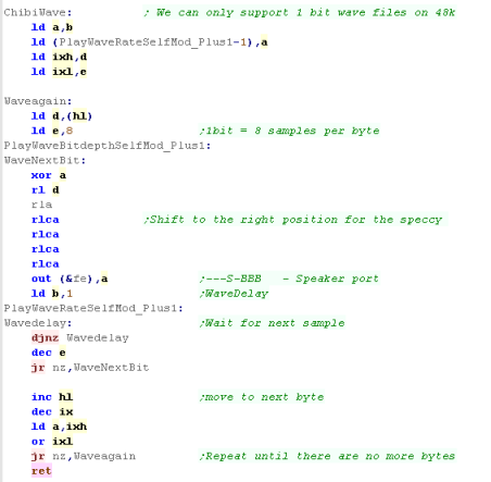
| The Spectrum 128k+ also have an AY sound chip, and this code will work on those systems too... but if you want to support the 48k spectrum, you'll want to use a 1 bit per sample file, and we'll learn how to do that in a later lesson! |  |
The DMA CPC+ Registers
The CPC+ has three DMA 'Channels'... each reads in one 2-byte (one command) word every 'tick' at a frequency of 15khz... there are 3 channels to allow all 3 AY channels to be changed at the same time on a 'tick'... however it is perfectly possible to use DMA channel 0 to change AY channel 1(B) or 2(C)
Every channel has a DMA address and a Prescaler
The DMA address is a pair of bytes which point to the sound data - which must be in the MAIN 64k of memory - it cannot be in ROM or 128k ram. it must also be on an EVEN BYTE - so put an ALIGN 2 before the data
There is a 'Prescaler' this affects the PAUSE command (and only that command) - to allow for the playback speed to be reduced....
Finally, there is a Control/Status register... Writing 1 to this will turn a channels DMA on (starting the data transfer)... This can be read during your interrupt handler to see what has caused an interrupt - Bit 7=1 means Vblank just occurred...Bits 6-4=1 mean that one of the DMA channels caused an interrupt - this can be used to 'alert' when the playback of a sample has ended so another sample can be queued.
| Function | Format | Channel 0 | Channel 1 | Channel 2 | Global |
| DMA
Data Address 2 bytes - Little Endien (LH) |
LLLLLLLL HHHHHHHH | &6C00 / 01 | &6C04 / 05 | &6C08 / 09 | |
| Prescaler
Playback Speed |
NNNNNNNN | &6C02 | &6C06 | &6C0A | |
| Control/Status
Register Write:Start DMA Read:Interrupts occured) |
W: -----210 R: V012---- |
&6C0F |
DMA Commands
The DMA has a very limited set of
commands - each is one word in size!
| Command | Bytes | Purpose |
| LOAD | &0RVV | Set AY Register R to V |
| PAUSE | &1NNN | Wait N*prescaler ticks - if we have 3+ samples that are the same we can use this to reduce the wav file size |
| REPEAT | &2NNN | Repeat command - this is like FOR I=0 to NNN |
| NOP | $4000 | Do nothing this tick |
| LOOP | &4001 | return to repeat point - this is like NEXT |
| INTerrupt | &4010 | Cause an interrupt - Status register bit 6-4 will be set depending on current channel |
| STOP | &4020 | Stop the DMA - end of the sound script |
| If you want to use
DMA to play one sound sample after another - or you want to
keep filling a buffer (of calculated/decompressed samples) -
you may want to have an INT command (&4010) at the end of
your list - this will cause an RST7 call to &0038 Your interrupt handler could then check &6C0F to see if the interrupt was caused by VBLANK or the DMA and act accordingly! |
 |
A complete example!
 |
If you've
been following these tutorials, you should understand these
commands... if not please see Lesson
P13 - we covered the CPC+ functions in that lesson |
Converting a WAV file for DMA via ChibiWave converter
| The
Prescaler
only affects PAUSE commands - but as we added a load into
the data (as part of compression) it will probably work
OK... technically the playback speed will not be even, but
in practacle terms, there's no noticeable difference |
 |
 |
Playing Sound Samples on the ZX Spectrum Beeper |
 |
We could
convert 4 bit samples to get them to play on the Spectrum
beeper, but it would be a waste of memory! That said if your game was going to support AY on 128k systems, and Beeper on 48k ones, it may be worth it! |
 |
Playing Sound Samples on the Camputers Lynx |
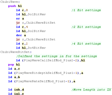
| The Camputers lynx a 'beeper speaker'.. but unlike the
spectrum is uses a 6 bit volume level We use port &84 to set the volume, we just need to shift the bits 2 to the left to pad the 4 bit sample out to 6 bits |
 |
 |
Playing Sound Samples on the Sam Coupe |
 |
Figuring
out how to make the wave play well on the Sam Coupe was a pain
in the ass! The Author of these tutorials cheated, and disasembled the 'Megablast demo' on FRED Magazine Issue 12 (1991) to figure out how to do it right!... Remember! if you can't figure it out yourself, just steal someone elses good ideas! |
| If
you want to see some super impressive Sam Coupe sound, check
out SAM
MOD player by Stefan Drissen! It's far better than the sound in this tutorial, it can handle 4 channels, and It's even open source! |
 |
    
|
Lesson
P38
-
Playing Digital Sound with WAV on the Sega
MasterSystem/GameGear, Elan Enterprise and GameBoy/GBC We've looked at most of our systems now, but there's still a few left, fortunately, it's all pretty similar, just like before we just need to switch our volume levels to get the job done... Lets finish the job!! |
 |
 |
 |
 |
We're just
covering the differences here... so please see Lesson
P35... We covered the
basics of how ChibiWave works, the concept of playing
digital sound, and how to convert wave files with
ChibiWave! |
 |
Playing Sound Samples on the Enterprise |
| The Enterprise is pretty easy, we use ports &A8 and
&AC to set the Left and Right sound channel volumes The EP128 has a 6 bit volume, but we're only using 4 bit samples,so we have to shift left by 2 bits |
 |
 |
Playing Sound Samples on the SMS/GG |
| The SMS/GG version of ChibiWave
is slightly different, rather than using Self modifying code,
we use IX and IY to store our extra values... Also rather than a direct CALL , we use a JP(IY) to execute the required sample converter. |
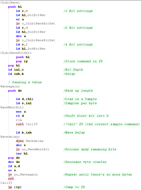 |
| On the Sega Mastersystem, we just need to set the top 4 bits to %1101 to set the volume, the remaining 4 bits are the volume level |  |
| This
version of ChibiWave will work on other systems too... just
change the 'volume command'! Depending on your system, and what you use the registers for, you may prefer this version that can run from ROM... or the version that needs IX and IY... Remember, some systems like the Speccy use IY in their firmware! |
 |
 |
Playing Sound Samples on the GB/GBC |
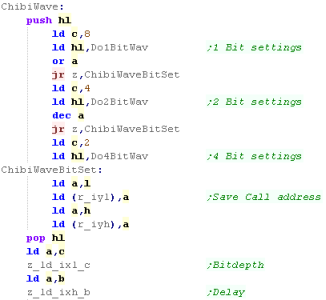
| On the Gameboy we have to do
things differently, because of the limited command set. We use bytes of ram to simulate IX and IY - but otherwise the code is basically the same as the SMS/GG version |
 |
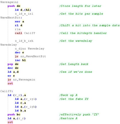
| Again our main code is
virtually the same, the significant change is the 'Call IY'
command... We have to use BC as a temporary pair, load our IY values into that, push them onto the stack, and then RETurn The result is the same as jumping to IY |
 |
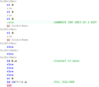
| Finally the job of setting the
volume level... On the Gameboy our volume levels are only 3 bit - so we ignore the 4th bit of our samples, When we set the volume levels, we need to set 3 bits of the top nibble, and 3 bits of the bottom nibble - this sets the Left and Right channels |
 |
 |
The Gameboy DOES have a digital sound channel
that can play 4 bit samples - but it uses just 32 bytes of
samples (64 samples)... In theory this could mean we could do better sound, but it seems impossible to 'stream' data into this bank - as the channel needs to be disabled when the data is updated, and we can't detect when the buffer has been played... |
 |
Lesson
P39
-
Setting the CPC screen with CRTC registers CRTC registers define the position and shape of the screen.... they allow us to do crazy things, like resize and hardware scroll the screen... they also allow page flipping - and are generally responsible for the impressive demos the CPC has gained over recent years. Lets check out the CRTC registers and see what they can do! |
 |
 CPC_CRTC_test.asm
|
 |
CRTC
| When we want to reconfigure CRTC registers we do so by writing
to the CRTC, The CRTC registers are selected with &BCxx (where xx is the register number), We then set the new value with &BDxx |
|
CRTC - Registers
CRTC registers will configure the Logical screen we draw on, and the physical screen shown by the Analog monitor...
You'll want to leave many of the settings alone, as they'll just result in a corrupt screen you can't view!... the ones that are interesting and easy to change are in yellow, more difficult but interesting ones are in Orange
The default value for a normal CPC screen, a 'Spectrum sized' 256x192, and Overscan screen with no border are shown!
| Reg Num | Name | Range | Bits | Default
Value |
Speccy 256x192 |
Overscan 384x272(26k) |
Details |
| &00 | Horizontal Total | 0-255 | DDDDDDDD | 63 | 63 | 63 | Physical width of screen � Leave alone! |
| &01 | Horizontal Displayed | 0-255 | DDDDDDDD | 40 | 32 | 48 | Logical width in Chars (8 pixels in mode 1) |
| &02 | Horizontal Sync Position | 0-255 | DDDDDDDD | 46 | 42 | 51 | Logical Xpos |
| &03 | Horizontal and Vertical Sync Widths | 0-15,0-15 | VVVVHHHH | 142 | 134 | 142 | Physical width of screen � Leave alone! |
| &04 | Vertical Total | 0-127 | -DDDDDDD | 38 | 38 | 38 | Physical height of screen � Leave alone! |
| &05 | Vertical Total Adjust | 0-31 | ---DDDDD | 0 | 0 | 0 | Scanline Offset |
| &06 | Vertical Displayed | 0-127 | -DDDDDDD | 25 | 24 | 34 | Logical Height in Chars (8 Pixels) |
| &07 | Vertical Sync position | 0-127 | -DDDDDDD | 30 | 31 | 35 | Logical Ypos of screen |
| &08 | Interlace and Skew | 0-3 | ------DD | 0 | 0 | 0 | 0/2=off 1/3=on � Leave alone! |
| &09 | Maximum Raster Address | 0-31 | ---DDDDD | 7 | 7 | 7 | Max Raster Address � Leave alone! |
| &0A | Cursor Start Raster | 0-127 | -DDDDDDD | 0 | 0 | 0 | |
| &0B | Cursor End Raster | 0-31 | ---DDDDD | 0 | 0 | 0 | |
| &0C | Display Start Address (H) | 0-63 | xxPPSSOO | 00 /
16 / 32 / 48 |
00 /
16 / 32 / 48 |
12+1 /
28 / 44+1 / 60 |
PP=Screen
Page (11=C000) S=Size(11=32k else 16k) O=Offset |
| &0D | Display Start Address (L) | 0-255 | OOOOOOOO | 0 | 0 | 0 | O=Offset |
| &0E | Cursor Address (H) | 0-63 | --DDDDDD | 0 | 0 | 0 | |
| &0F | Cursor Address (L) | 0-255 | DDDDDDDD | 0 | 0 | 0 | |
| &10 | Light Pen Address (H) | 0-63 | --DDDDDD | 0 | 0 | 0 | Read Only |
| &11 | Light Pen Address (L) | 0-255 | DDDDDDDD | 0 | 0 | 0 | Read Only |
 |
We can
effect a Scroll by changing &0D (13)... each change to
this register will move the screen by one mode1 character We can effect fine Horizontal scrolling by changing &05... and vertical scrolling with &03 - but BEWARE! these may work on the original Amstrad monitor - but people using TFT's may see the screen jump and flicker when you do this - so your game will be unplayable on their machines!... but maybe that'll learn them for not paying respect to the CTM644! |
Double buffering
Double buffering means using two screen buffers - one which is being shown.... and another being drawn.... the advantage is this means we can build up our screen over time without visible flickering, the disadvantage is we need 32k of ram to hold 2 screens.!
To set the visible screen buffer we need to change PP in register &0C... writing 48 will set the visible screen to &C000 - writing 16 will set it to &4000 and 32 will set it to &8000...
Many games that use double buffering will set the screen to &4000... ChibiAkumas used &8000 so that the swappable bank at &4000-&7FFF - but this meant the AmsDOS settings at around &A600 were lost...
If you wanted to use memory &0000 for the screen, we'd either need to never turn on interrupts, or use IM2 - because IM1 uses &0038 as the interrupt call.
| Double
buffering is great, but you may not want to use it! If you can redraw the screen quickly in small sections you can get away with a single buffer - this works best for 464 games (leaving 48k free for game code) and also for games with super high frame rate... Games like Dizzy and Skweek used single buffers, and this allowed more ram for sprite data while keeping 64k support For a game like ChibiAkumas - where everything changed every frame (due to background parallax and high sprite/bullet count) two buffers were essential! |
 |
Using and Testing the registers!
| We're going to define a simple
function called SetCRTC... it will set CRTC reg C to value A We're going to use this in a little test program! |
 |
| We're not going to look at the
program code - it's long and not particularly related to the
CRTC - what it does is let us see the changes to each register
onscreen! To use it, load "CPC_CRTC_TEST.asm" in Winape and compile it. then type Call &8000 in basic to start the program |
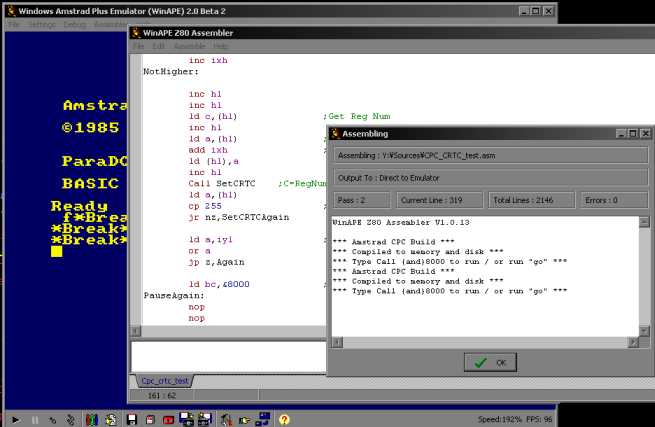 |
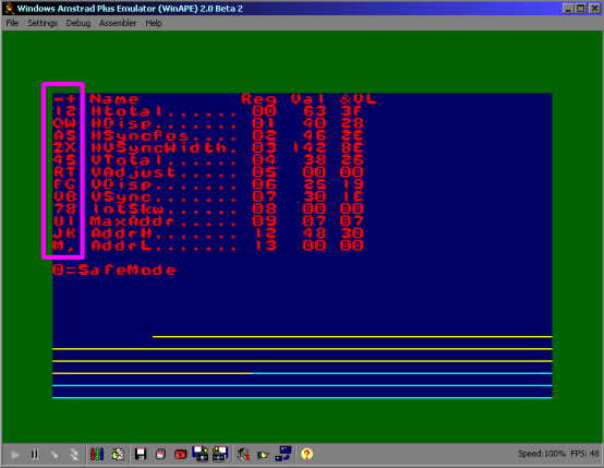
| You should see the screen to the
right... Note: there are some yellow and cyan lines at the bottom of the screen - these are NOT corruption - they are filled bytes of memory to show the top of the &FE00-&FFFF range On the left are two letters - these are keys you can press to change the register - for example J and K will change the address of the start of the screen! Try the keys - you'll see the settings in VAL (decimal) and &VL (hex) and the effect onscreen! |
 |
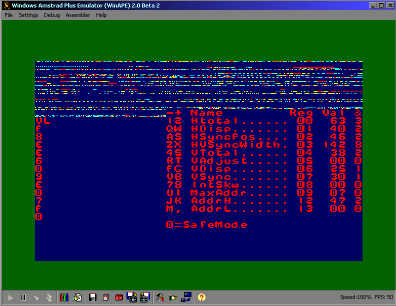
| Because our text drawing code
hasn't changed, Altering AddrH will make the screen look weird -
we'd need to reprogram our drawing code to accommodate our new
settings to make it all work seamlessly.. |
 |
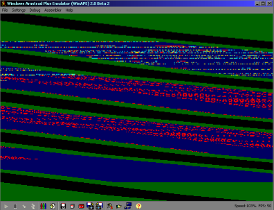
| It's very easy to use some
setting that are impossible to view, and now we can't see the
settings any more! The tool has a Safe Mode to get around this... Press 0 (zero)... this will turn on safe mode! In Safe Mode, the settings you choose will be applied for an instant, and then it will flip back to the defaults - so you can see the effect of the settings you chose, and still see all the options on a normal screen |
 |
 |
This program
just allows you to test what each register does - and find
suitable settings for the screen size and position you need... Once you've done that, you'll need to reprogram your sprite, font and other drawing routines to work with the new screen position and orientation. |
 |
Lesson
P40
-
Syncronized mode switches for 320x200 @ 16 color EGX graphics
on the Amstrad CPC With Imperial Mahjong, Cargosoft invented a new graphics mode... By switching between Mode 0 and Mode 1 every single line, we can create graphics which have the colors of Mode 0, with the high resolution of mode 1... Of course we'll need to design our graphics accordingly... but as always in these tutorials - AkuSprite Editor can do the job! |
 |
 CPC_ModeEGX.asm
|
 |
Feel the power of EGX!... the
theory!
Lets take a look at a sample EGX version of the Chibiakumas Screen (based on the MSX version)
Lets take a look at a sample EGX version of the Chibiakumas Screen (based on the MSX version)
 |
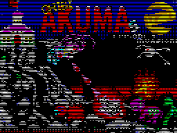 |
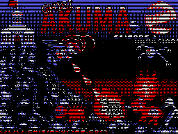 |
| EGX - full Screen The Full EGX screen as we see it in the CPC, each alternate line is Mode 1/0, and the screen has been optimized so where possible the graphics have the smoothness of mode 1, but the improved color of Mode 0 |
Mode 0 part The Mode 0 lines (even lines) have full 16 colors, and give the game better color than could be managed in Mode 1 |
Mode 1 part The Mode 1 lines (odd lines) are 4 colors - we've selected the most used 4 colors to allow us to 'blend' the mode 1 and mode 0 lines, we've also positioned the text, so that the top and bottom line of the text are mode one - allowing for smooth O's and curves in letters |
Hints for EGX
1. Use the 4 most common colors for your Mode 1 graphics (or colors which will balence out the mode 0 colors)
2. Your Mode 0 pixels must be the equivalent of 2 pixels wide - so you may want to make parts of the mode 1 wider, so the Mode 0 parts don't look 'wavy'
3. It's a good idea to Move objects to take advantage of the higher resolution Mode 1 lines... the "www.chibiakumas.com" and "Episode 1" have been redesigned, and positioned to allow the tops and bottoms to be Mode 1 (and made wider to match Mode 0's capabilities)
4. I drew this EGX screen in Krita... the screen was exported from Akusprite Editor... Once as Mode 1, Once as Mode 0... A 'Transparency mask' was used to combine the two... The result was pasted back into AkuSprite Editor, and tweaks were made.
The Gate Array:
We're going to be using the Gate
array at port &7Fxx... Really EGX is pretty simple we just
switch modes fast!... the tricky thing is the timing!
| 7 | 6 | 5 | 4 | 3 | 2 | 1 | 0 | Name | Bit meanings |
| 1 | 0 | - | I | H | L | M | M | Rom / Mode | I= Interrupt mode H=High rom bank L=Low rom bank M=screen mode |
Timing!
Thinking of the CPC screen in Mode 1...
Each line of the CPC screen is 40 usable characters... but adding the
'border area' it's 64...
the NOP command takes the equivalent of 1 character... so we can wait a full line of pixels with 64x NOPs... we can define these easily with DS 64
Now, we could change mode... wait around 64 NOPs (less the time our mode change commands took) and do another mode change, BUT the CPC can only physically change modes once per line - If we time things carefully, and change to Mode 1 at the end of a line, then instantly change back to Mode 0 as the next line starts, then we've done all our changes, and then we can wait 128 NOPs (less the time our mode change commands took)
If we're just doing a simple test, then this isn't too important, but if we were developing a game, we'd have to put all our game logic in that 128 NOPs to keep the screen visible, and allow our game to work
| If we
screw up our timings, you'll see something go wrong... with
this example, if the 'Mode Flip' doesn't happen at the end
of the line, you'll see no mode changes at all (as both
happen on the same line, cancellinjg each other out before
the CRTC sees either!) If something goes wrong, and our code takes more time than the screen takes to draw, then the effect will toggle on and off alternating frames... Try to start simply with an easy example, and take things from there. |
 |
 |
As they only
happen 6 times a screen (every 52 lines) Interrupts can't help
us achieve this trick!... we'll have no choice but to design
our code around changing the screen mode every two lines... The result is writing our code will be a pain, and we'll end up use a lot of our Z80 power on the effect... |
Using EGX
| AkuSprite Editor has a special 'EGX' View mode, it will simulate the display of a 4/16 color alternating screen layout (with the top line as Mode 1) | 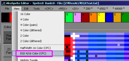 |
| We're going going to start by
disabling the firmware interrupt handler, we write a "EI RET"
to &0038 The code in today's example are very sensitive to timing... we're going to sync to the screen redraw by waiting for a screen to start redrawing We read in a byte from port &F5xx... if bit 0 is 1 then we're at the top of the screen Now we're going to HALT... to wait for the Vblank to end... this allows us to be sure any code that follows will run in a consistant way, syncronized with the screen drawing of the CPC |
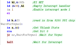 |
| We're going to start the main loop...We need to start our
'Mode Manipulation' at the start of the visible screen... We check again for the start of a new Vblank, so we know we're at the top of a new screen. When we are, then we disable interupts, and wait 64 lines until we get to the first line of the active screen. We're going to set IYL to 100 - this is the number of line pairs in the screen (100*2 = 200) Finally we have another 32 NOPs (via the DS 32)... this will wait until the end of the raster line |
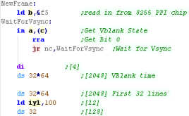 |
| We're using port &7Fxx to
set the screen mode, we also need to turn off the High and Low
rom... We set the screen mode to 0, then swith it back to mode 1... Because we're at the end of a line, the Mode 1 change happens on a different line... and as the screen mode can only change once a line, the change to Mode 1 happens a line later... We've effectively created 2 lines with alternating modes, with 5 concecutive commands! We now have a delay...DS 110 is effctively 110 NOPs... this to wait until the next pair of lines... It's at this time we'd need to do any game logic or music playing - and we'd have to make sure our code was 'timed' to take exactly 110 NOPS, otherwise the EGX effect wouldn't be stable! |
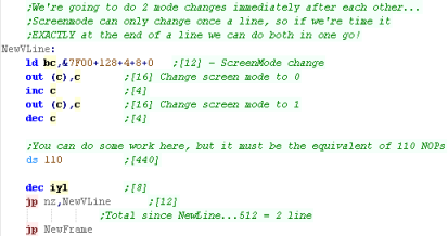 |
| We need to 'Call &8000' to enable the effect, but you'll need to make sure you have a proper screen to view!... a sample screen 'EGXTest.scr' is provided in the sources.7z (in the ResALL folder) |  |
| For the effect to be balenced the code for
each line needs to be the equivalent of 64 NOPS...
On the CPC each command will take a multiple of 4
'ticks'... so a command like 'Dec IX' which takes 10
'ticks' in the Z80 documenation actually takes 12.. For the full details check out the docomentation on CPC-Live |
 |
Continue to Page 5
Back to Page 3
| View Options |
| Default Dark |
| Simple (Hide this menu) |
| Print Mode (white background) |
| Top Menu |
| ***Main Menu*** |
| Youtube channel |
| Patreon |
| Introduction to Assembly (Basics for absolute beginners) |
| Amazon Affiliate Link |
| AkuSprite Editor |
| ChibiTracker |
| Dec/Bin/Hex/Oct/Ascii Table |
| Alt Tech |
| Archive.org |
| Bitchute |
| Odysee |
| Rumble |
| DailyMotion |
| Please note: I wlll upload more content to these alt platforms based on the views they bring in |
| Z80 Content |
| ***Z80 Tutorial List*** |
| Learn Z80 Assembly (2021) |
| Learn Z80 Assembly (old) |
| Hello World |
| Simple Samples |
| Advanced Series |
| Multiplatform Series |
| Platform Specific Series |
| ChibiAkumas Series |
| Grime Z80 |
| Z80 Downloads |
| Z80 Cheatsheet |
| Sources.7z |
| DevTools kit |
| Z80 Platforms |
| Amstrad CPC |
| Elan Enterprise |
| Gameboy & Gameboy Color |
| Master System & GameGear |
| MSX & MSX2 |
| Sam Coupe |
| TI-83 |
| ZX Spectrum |
| Spectrum NEXT |
| Camputers Lynx |
| 6502 Content |
| ***6502 Tutorial List*** |
| Learn 6502 Assembly |
| Advanced Series |
| Platform Specific Series |
| Hello World Series |
| Simple Samples |
| Grime 6502 |
| 6502 Downloads |
| 6502 Cheatsheet |
| Sources.7z |
| DevTools kit |
| 6502 Platforms |
| Apple IIe |
| Atari 800 and 5200 |
| Atari Lynx |
| BBC Micro |
| Commodore 64 |
| Commodore PET |
| Commander x16 |
| Super Nintendo (SNES) |
| Nintendo NES / Famicom |
| PC Engine (Turbografx-16) |
| Vic 20 |
| 68000 Content |
| ***68000 Tutorial List*** |
| Learn 68000 Assembly |
| Hello World Series |
| Platform Specific Series |
| Simple Samples |
| Grime 68000 |
| 68000 Downloads |
| 68000 Cheatsheet |
| Sources.7z |
| DevTools kit |
| 68000 Platforms |
| Amiga 500 |
| Atari ST |
| Neo Geo |
| Sega Genesis / Mega Drive |
| Sinclair QL |
| X68000 (Sharp x68k) |
| 8086 Content |
| Learn 8086 Assembly |
| Platform Specific Series |
| Hello World Series |
| Simple Samples |
| 8086 Downloads |
| 8086 Cheatsheet |
| Sources.7z |
| DevTools kit |
| 8086 Platforms |
| Wonderswan |
| MsDos |
| ARM Content |
| Learn ARM Assembly |
| Learn ARM Thumb Assembly |
| Platform Specific Series |
| Hello World |
| Simple Samples |
| ARM Downloads |
| ARM Cheatsheet |
| Sources.7z |
| DevTools kit |
| ARM Platforms |
| Gameboy Advance |
| Nintendo DS |
| Risc Os |
| Risc-V Content |
| Learn Risc-V Assembly |
| Risc-V Downloads |
| Risc-V Cheatsheet |
| Sources.7z |
| DevTools kit |
| MIPS Content |
| Learn Risc-V Assembly |
| Platform Specific Series |
| Hello World |
| Simple Samples |
| MIPS Downloads |
| MIPS Cheatsheet |
| Sources.7z |
| DevTools kit |
| MIPS Platforms |
| Playstation |
| N64 |
| PDP-11 Content |
| Learn PDP-11 Assembly |
| Platform Specific Series |
| Simple Samples |
| PDP-11 Downloads |
| PDP-11 Cheatsheet |
| Sources.7z |
| DevTools kit |
| PDP-11 Platforms |
| PDP-11 |
| UKNC |
| TMS9900 Content |
| Learn TMS9900 Assembly |
| Platform Specific Series |
| Hello World |
| TMS9900 Downloads |
| TMS9900 Cheatsheet |
| Sources.7z |
| DevTools kit |
| TMS9900 Platforms |
| Ti 99 |
| 6809 Content |
| Learn 6809 Assembly |
| Learn 6309 Assembly |
| Platform Specific Series |
| Hello World Series |
| Simple Samples |
| 6809 Downloads |
| 6809/6309 Cheatsheet |
| Sources.7z |
| DevTools kit |
| 6809 Platforms |
| Dragon 32/Tandy Coco |
| Fujitsu FM7 |
| TRS-80 Coco 3 |
| Vectrex |
| 65816 Content |
| Learn 65816 Assembly |
| Hello World |
| Simple Samples |
| 65816 Downloads |
| 65816 Cheatsheet |
| Sources.7z |
| DevTools kit |
| 65816 Platforms |
| SNES |
| eZ80 Content |
| Learn eZ80 Assembly |
| Platform Specific Series |
| eZ80 Downloads |
| eZ80 Cheatsheet |
| Sources.7z |
| DevTools kit |
| eZ80 Platforms |
| Ti84 PCE |
| IBM370 Content |
| Learn IBM370 Assembly |
| Simple Samples |
| IBM370 Downloads |
| IBM370 Cheatsheet |
| Sources.7z |
| DevTools kit |
| Super-H Content |
| Learn SH2 Assembly |
| Hello World Series |
| Simple Samples |
| SH2 Downloads |
| SH2 Cheatsheet |
| Sources.7z |
| DevTools kit |
| SH2 Platforms |
| 32x |
| Saturn |
| PowerPC Content |
| Learn PowerPC Assembly |
| Hello World Series |
| Simple Samples |
| PowerPC Downloads |
| PowerPC Cheatsheet |
| Sources.7z |
| DevTools kit |
| PowerPC Platforms |
| Gamecube |
| Work in Progress |
| ChibiAndroids |
| Misc bits |
| Ruby programming |
Buy my Assembly programming book
on Amazon in Print or Kindle!



Available worldwide!
Search 'ChibiAkumas' on
your local Amazon website!
Click here for more info!


Buy my Assembly programming book
on Amazon in Print or Kindle!


Available worldwide!
Search 'ChibiAkumas' on
your local Amazon website!
Click here for more info!


Buy my Assembly programming book
on Amazon in Print or Kindle!


Available worldwide!
Search 'ChibiAkumas' on
your local Amazon website!
Click here for more info!


