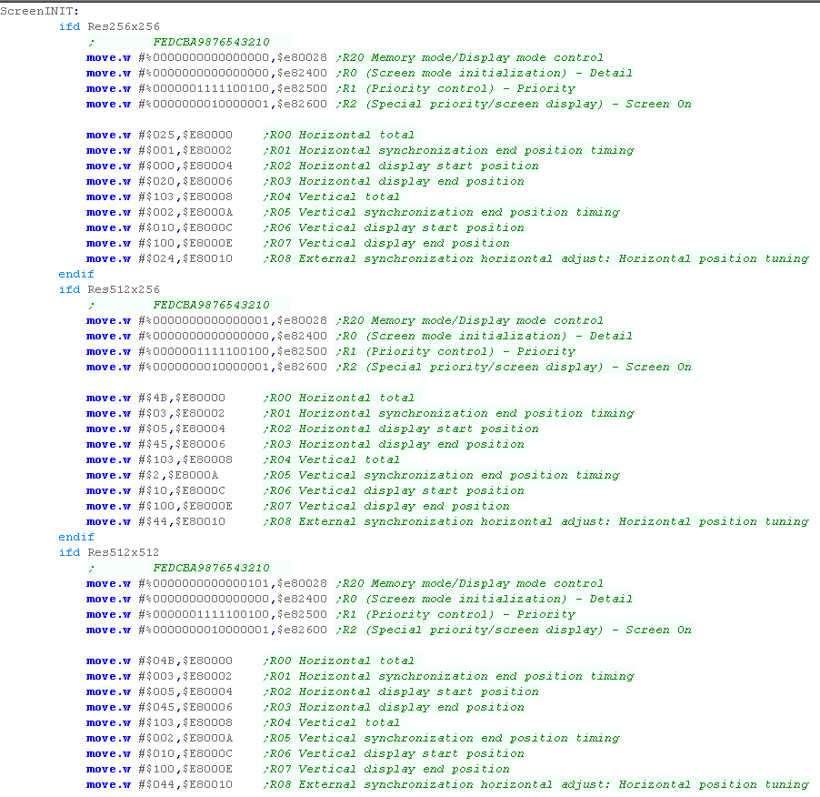
The X68000 screen is memory
maps to the hardware, but it's slightly odd compared to other
systems...
Each screen pixel uses two bytes of memory WHATEVER the screen
mode! - so whether you're using 4bpp or 8bpp, you're still
going to use |
| Address |
Purpose |
| $c00000 |
Graphics
Vram
� Page 0 |
| $c80000 |
Graphics
Vram
� Page 1 |
| $d00000 |
Graphics
Vram
� Page 2 |
| $d80000 |
Graphics
Vram
� Page 3 |
|
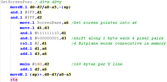
We're going to use the A6
register to write data to the screen - we'll use a
'GetScreenPos' command to convert an X,Y pos (in D1,D2)
We're using Graphics Screen 0 - which starts at $C00000...
Each X pixel takes 2 bytes - so we do a ROL to shift X left 1
bit
Each Y line is 1024 bytes, so we do 8+2 ROL's to shift Y left
10 bits... we can't do ROL #10, the command doesn't support it |
 |
| We have a GetNextLine command
to move down a line as well... |
 |
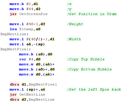
Using the bitmap routine
We can show a bitmap sprite to
the screen, buy using the GetScreenPos command to set the
correct memory position in A6
We're going to read in a sprite in 'Packed format' where both
nibbles of the byte is used - we'll need to split these up and
write them in separate words to the screen memory
We need to use GetNextLine to move down after each complete
line. |
 |
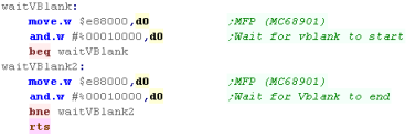
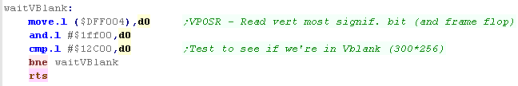
Bonus!... waiting for VSync to slow down a game
VSync on the X68000 is possible
via the MFP (MC68901)... we can test bit 4 to see if the
screen is in Vsync... by waiting for Vsync to start and end,
we can make sure a new vsync starts before we continue
processing...
This was used in the Grime 68000 game |
 |
 |
This Vsync
routine was used in Grime 68000 to slow down the game, but
it's not perfect, on a 100mhz x68 it's much faster than a
1st gen machine... but this is the best the author has
managed to do so far! |
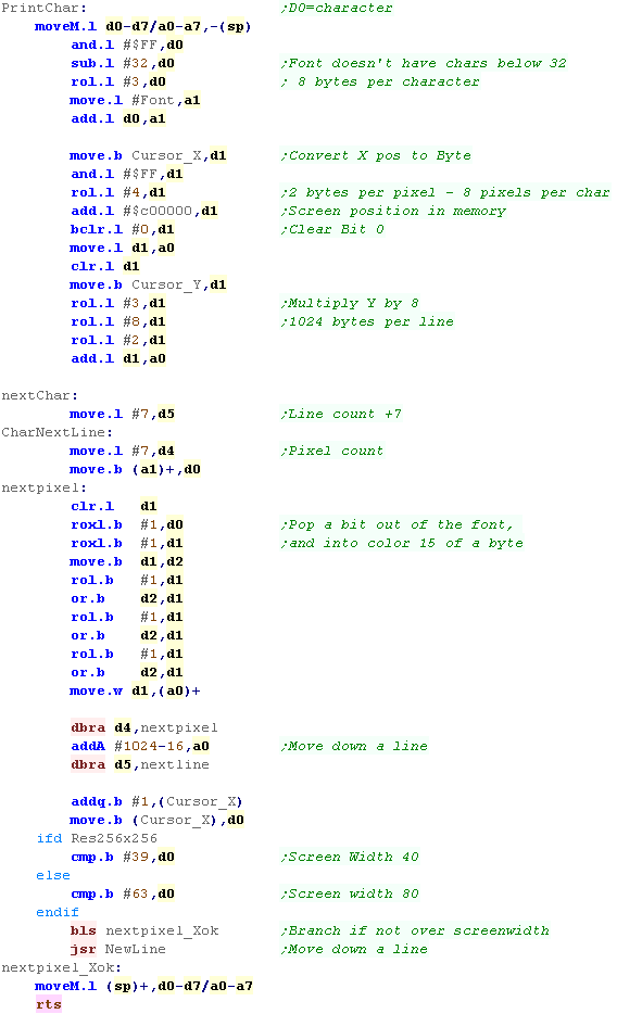
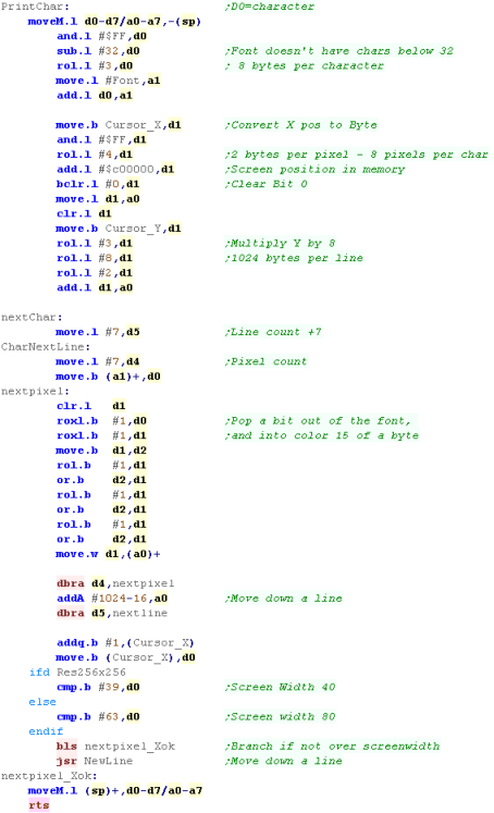
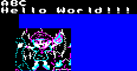
PrintChar - using out Bitmap font to print
characters
Our 'PrintChar' routine will
show an Ascii character in D0 to the screen...
Essentially we're using the same code as above, but now we're
using Cursor_X and Cursor_Y as 'character position' for
calculating the screen postion
When it comes to actually plotting to the screen, we're
popping of a bit of the font lines, and moving it to 'color
15' of the byte, before drawing it to the screen.
Once we've drawn the character to the screen, we increase the
X position - and see if we've reached the width of the screen,
if we have then we run the NewLine command to wrap to the next
line. |
 |
| You'll
need
to define Cursor_X and Cursor_Y in ram somewhere... also not
there's some simple LOCATE and CLS commands not shown here,
download the sources.z7 if you want to see them! |
 |
 |
Lesson
P2 - Bitmap Functions on the Atari ST
The Atari ST has a ram based screen - we can just allocate
some memory, and write data to it to get it on screen...
The layout is a bit odd - it's split into bitplaines in 16
pixel Words... lets see what that means! |
 |
 |
|
 |
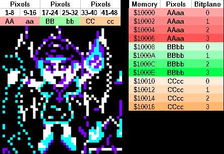
Screen Layout
Lets take a look at how bitmap data is stored on the Atari
ST...
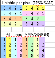
The screen is 16 color - which means we need 4 bits for each
color...
These colors are stored in 'Bitplanes' - this means each byte
defines one of the color bits for 8 pixels.
On the Atari ST pixel data is stored in words... 16 pixels
worth of data for a single bitpalne are stored in a Word...
the next word will be the next bitplane for the same 16
pixels... and so on for all 3 bitplanes...
After all 4 bitplanes for the first 16 pixels, the next 16
pixels will start...
The screen is 320 pixels wide, so each line is 160 bytes
across... and Line 1 is 160 bytes after Line 0 in the memory. |
 |
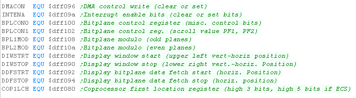
Hardware Registers
The Atari ST uses memory mapped registers to control the
screen...
These registers are defined from $FF8200-$FF8260.... Note that because
the 68000 uses a 24 bit address bus, the byte is usused - you may see
in some documentation addresses like $FF8200 shown as $FFFF8200...
these are the same address.
We need to define an area of our memory for screen use... we use
$FF8200-$FF8202 to define it but only the bottom byte of each
word address ... the screen will take 32000 bytes of data, however we
can only specify the top 16 bits of the 24 bit address... this means
the bottom byte of the screen address must be Zero - eg : $????00
The Atari ST has 3 screen modes - we'll be using mode 0 in these
tutorials, which give 16 colors at 320x200... we set the screen mode
by writing to $FF8260
We can also set colors with addresses $FF8240-$FF825F - one word
defines each color.
| Address |
Mode |
Bits |
Purpose |
Details |
| FF8200 |
RW |
--------
HHHHHHHH |
Video
Base H |
Need
32256 bytes per screen |
| FF8202 |
EW |
--------
MMMMMMMM |
Video
Base M |
Can�t
specify L byte |
| FF8240 |
RW |
-----RRR
-GGG-BBB |
Palette
Color 0 |
|
| FF8242 |
RW |
-----RRR
-GGG-BBB |
Palette
Color 1 |
|
| FF8244 |
RW |
-----RRR
-GGG-BBB |
Palette
Color 2 |
|
| FF8246 |
RW |
-----RRR
-GGG-BBB |
Palette
Color 3 |
|
| FF8248 |
RW |
-----RRR
-GGG-BBB |
Palette
Color 4 |
|
| FF824A |
RW |
-----RRR
-GGG-BBB |
Palette
Color 5 |
|
| FF824C |
RW |
-----RRR
-GGG-BBB |
Palette
Color 6 |
|
| FF824E |
RW |
-----RRR
-GGG-BBB |
Palette
Color 7 |
|
| FF8250 |
RW |
-----RRR
-GGG-BBB |
Palette
Color 8 |
|
| FF8252 |
RW |
-----RRR
-GGG-BBB |
Palette
Color 9 |
|
| FF8254 |
RW |
-----RRR
-GGG-BBB |
Palette
Color 10 |
|
| FF8256 |
RW |
-----RRR
-GGG-BBB |
Palette
Color 11 |
|
| FF8258 |
RW |
-----RRR
-GGG-BBB |
Palette
Color 12 |
|
| FF825A |
RW |
-----RRR
-GGG-BBB |
Palette
Color 13 |
|
| FF825C |
RW |
-----RRR
-GGG-BBB |
Palette
Color 14 |
|
| FF825E |
RW |
-----RRR
-GGG-BBB |
Palette
Color 15 |
|
| FF8260 |
RW |
------SS |
Screen
Mode |
00=320x200
@4bpp
01=640x200 @2bpp
11=640x400 @1bpp |
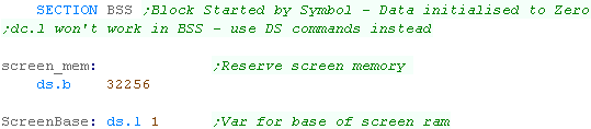
Setting up the screen
We need to define some ram for the screen...
we're going to define a 'BSS' section in our code...
Data in this section does not exist in the compiled file...
but any data areas in it will be allocated by the
operating system ... they will ALLWAYS be initialized to ZERO,
so we can only use DS to define areas, not DC
Because we need the bottom byte of the screen start to zero,
we're going to allocate 256 bytes more than we need. |
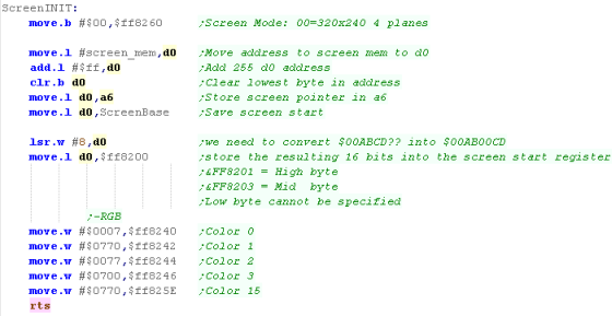
|
We'll start by changing the screen resolution by writing $00
to $FF8260
Now we need to use the address of the ram we defined in the
BSS section... however we need to zero align it - as we can't
set the Low byte of the screen address
Lets assume the screen_mem symbol has the address $00123456...
Our aligned screen will be $00123500... we'll store this in
'ScreenBase' ... but when we store this into $FF8200 - we need
the two bytes to be in the low bytes of the words... so we
shift it... converting $00120035
Finally, we'll define some basic colors to start us off
|
 |
Calculating a screen position with GetScreenPos
We're going to define our GetScreenPos function we'll take
an Xpos (in bytes) in D1, and a Ypos (in lines) in D2
We'll have to calculate an offset to our screen base... as the
4 bitplanes of16 pixels (2x4 bytes) are grouped together, for
every 16 pixels, we move 8 byte... we do this by
ignoring the bottom bit of the Xpos, and doing 2 bit shifts
but we need to move along one, to the middle of the word if
the selected screen byte is odd... we do this by adding the
bottom bit of the XPos
Each line of the screen has 160 bytes... so we multiply the
Ypos by 160, and add this to the screen position...
This gives us the resulting position to write our byte data to |

|
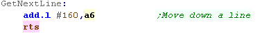
| If we want to move down a line, we can just add 160 to our
current position to do it. |
 |
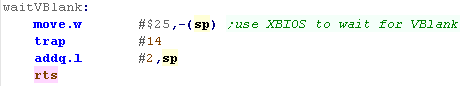
Waiting for VBlank
We may need to wait for VBlank to delay our games and make
them run at even speed...
We can use function $25 of Trap 14 (Xbios) to wait for the
vblank. |
 |
| Alternatively we can use the
Vblank counter at address $462 - this is a counter that's
updated by the firmware every time vblank occurs. |
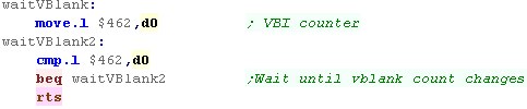 |
| Ideally,
we'd rather go direct to the hardware and detect VBLANK
rather than using the firmware, but the author of these
tutorials is too stupid to figure it out!... if you know
how, please give him a clue - and tell him how it works! |
 |
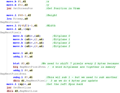
Showing a Bitmap to the screen
We're going to define our
bitmap with all 4 bitplanes in concecutive bytes (this is the
same format we'll use for the amiga)
This means we'll have to write all the bytes to the 4
bitplanes - and we'll have to move in an odd pattern:
We'll write 4 bytes (offset to point to the bitplane) -
move 1 byte , then write another 4 bytes (also offset to point
to the bitplane),
Finally we'll move another 7 bytes... this will move to the
start of the next word... and we'll repeat the procedure
again! |
 |
 |
We
could
use Atari ST native format, but there are advantages to
storing the data byte aligned, and converting it to word
alignment.
The reason we're doing this is it allow us to write to any
byte aligned X position - whereas if we used native Atari ST
screen foramt we'd have to be word aligned. |
 |
Lesson
P3 - using the FIX layer to draw bitmaps on the NeoGeo
The NeoGeo is not a bitmapped screen - so we can't set pixels
in memory ... and unlike other consoles, the NeoGeo's
backgrounds are made up of 16x16 Sprites not an 8x8 Tilemap...
However the NeoGeo does have an 8x8 FIX layer - which is
deigned for onscreen text and other such stuff - and to get us
started, we can use it to do our Chibiko Bitmap! |
|
|
|
|
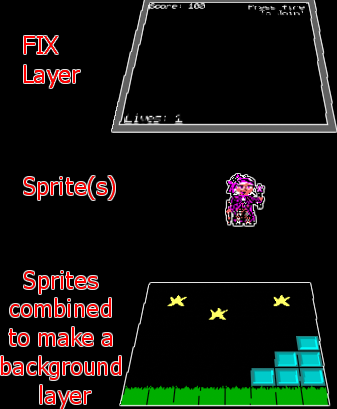
What is the Fix Layer
Most Console systems will have
2 types of graphics layer... a 'Tile Map' which is a grid of
predefined 'tiles'... these are usually 8x8 in size... on a 16
bit system, usually multiple layers of tilemaps exist to
define parallax...
On top of this we would add sprites to make our player
character and other such things...
But the NeoGeo HAS
NO TILEMAP! |
 |
So how does the NeoGeo work
with no Tilemap?
Well... sprites on the NeoGeo are 16 pixels wide, and can be
up to 512 pixels tall - but they can be combined!... and
because the NeoGeo is capable of a whopping 380 tiles, we can
combine 20 of them together to 'simulate' a tilemap!... this
is how background graphics are drawn on the Neogeo!
On top of this are our 'normal' sprites - enemies, player
characters and such...
There is one final layer, the 'Fix Layer'... this is made up
of 16 color 8x8 tiles, in a simple grid... it's designed to do
onscreen text and the like... but I used it in GrimeZ80 to do
all the game graphics... so if your needs are simple, and you
want 8x8 block graphics, it can be used for the job...
but don't worry, we'll learn about sprites later |
 |
|
Grime
68000 used the FIX map for all it's graphics... but we
should have probably used Sprites...
Sprites are 16x16 - but the NeoGeo has Hardware scaling, so
we could scale them down to 8x8 - We'll learn all about
Sprites in a later lesson! |
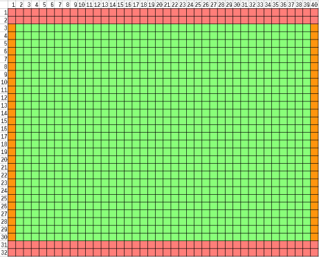
Mysteries of The
Fix Layer!
The Neogeo screen has a resolution of 320x224, and each tile
is 8x8 - giving an effective screen size of 40x28...
The actual tilemap is 40x32... the top and bottom two lines
are not show (Shown in red on the chart to the right)
However, because of the CRT layout - it is likely that the
left and rightmost 1 column will not be visible (Shown in
orange to the right)... this gives a visible screen of 38x28
The Fix Layer is positioned in VRAM at &7000 (each
position contains 1 word / 2 bytes)- each Tile is defined by
16 bits in the following format:
| F |
E |
D |
C |
B |
A |
7 |
8 |
|
7 |
6 |
5 |
4 |
3 |
2 |
1 |
0 |
| P |
P |
P |
P |
T |
T |
T |
T |
|
T |
T |
T |
T |
T |
T |
T |
T |
Where
P is the Palette
number, and T
is the Tile number
The fixmap appears at $7000 in Vram... tile data for the
Fixmap are in ROM
Each address contains a WORD...
Write a word to $3C0000 to select VRAM Address
Write a word to $3C0002 to Send data to VRAM
Tiles in memory are ordered in COLUMNS... so in memory (X,Y)
co-ordinate (0,1) comes after (0,0) ($7000)... and (1,0) comes
32 words ($7020) after (0,0)
For example - to set tile (0,2) to tile 256 in palette 1 (note
this is in the "May be offscreen" area, but should appear on
an emulator)
Move.W #$7002,d1
;Address - Tile 2
Move.W #$1100,d0
;PTTT
- Palette and tile
Move.w d1,$3C0000
;set address in vdp
Move.w d0,$3C0002
;set tile data in vdp |
| Start |
End |
Words |
Zone |
Description |
| $7000 |
$74FF |
4096 |
|
Fix map |
|
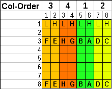
Fix Layer tiles are in an odd format!
Each tile is 8x8 at 4bpp ... so 32 bytes per tile...
The two nibbles of each byte represent 2 pixels , but they are
BACKWARDS... so the 1st (High) nibble is the 2nd pixel color,
and the 2nd nibble (Low) is the 1st pixel color
The bytes are stored in Columns, then rows... and the columns
are out of order too! .. Visible pixels ABCDEFGH are stored in
Ram in order FEHGBADC
The 8 bytes of each column are in normal top->bottom
format... so at least that:s something!
|
 |
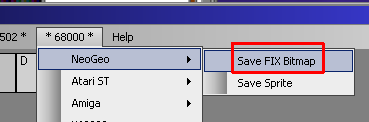
| My AkuSprite editor (used in
these tutorials) has support to export images in the correct
"FIX" format for the NeoGeo |
 |
|
The
FIX and SPRITE formats are different on the NeoGeo which is
VERY ANNOYING!
You can use AkuSprite Editor to create valid files - and
remember, it's open source, so if it doesn't do the job well
enough, you can use the source to make something better! |
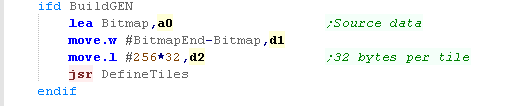
Defining our ROMS
via MAME XML
We need to define our FIX rom data in the NEOGeo.XML...
we'll split the fix data into 3 files...
NAME
specifies the filename
OFFSET specifies
the memory position in the 'ROM' of the Neogeo
SIZE
is technically the size of the file - but mame doesn't seem to
check if it's correct (Warning: it does with sprites!)
CRC /
SHA1 -
these are hashes of the rom - if they are incorrect MAME will
complain

we're defining 3 files
202-s1.s1 - This is the NEOGEO firmware
fonts, we'll leave them alone
FONT.FIX - This is the ChibiAkumas
font used by these tutorials, you'll need this for the
PrintChar routines to work
RawNEO.FIX - this is the bitmap data we're
going to use today to show 'Chibiko' onscreen! |
| If we want
to create a 'proper' rom file, we'll need to calculate the
correct Hashes, but it's quicker to skip it, and the game
will run, so it's OK for our testing |
 |
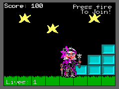
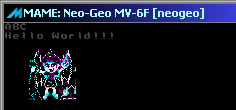
Getting
our bitmap to the screen
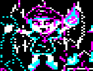
We're going to put our
'Chibiko' character on the screen, the sprite is 48x48, so
it's made up of 6x6 FIX tiles...
We'll set the correct positions of the fix tilemap to the
parts of the bitmap. |
 |
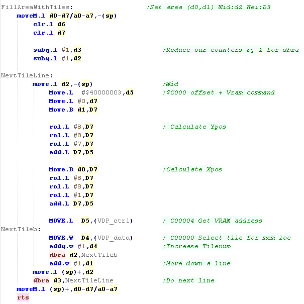
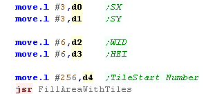
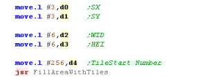
We're going to use a function
called FillAreaWithTiles... this will take a start XY
position, a Width and Height, and a start Tilenumber... it
will fill the entire area with consecutive tiles
Left->Right, Top->bottom
Note... the NeoGeo works the opposite way: Columns first, then
Rows
We're allocating tiles 0-255 for our font, so we're using
tile 256 for our Chibiko Bitmap |
 |
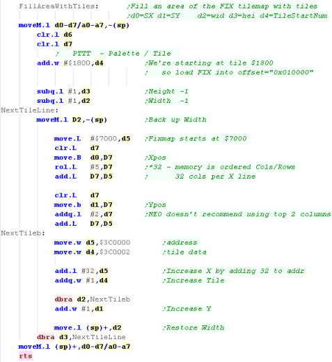
When we call our
FillAreaWithTiles function, we'll need to convert the X,Y
co-ordinate into a memory
The first 2048 tiles
($800) are used by the firmware - we're also going to use Palette 1
- so we add $1800 to the
tile number to get the data we write into VRAM
We then need to calculate the offset in the FIX map for the
tile we want to change... the fixmap is organized in
Column/Row order (Going down then Across)...
We do this by adding X*32+Y to the start address of the fixmap
($7000)
We shift the Xpos left 5 times with ROL.L #5 - multiplying X
by 32...
Because the top 2 lines of the NeoGeo screen are not viewable,
we add 2 to the Ypos
To set the Tile, we write the address we want to change to
$3C0000.... and the TileNumber/Palette to $3C0002
We repeat the procedure for each of the tiles we want to draw
to the screen. |
 |
 |
Lesson
P4 - Bitmap Functions on the Sinclair QL
The QL's graphics are visually very different to the other 16
bits (if you count the QL as 16 bit!!)
It uses a fixed palette, of 8 primaries (RGBCMYWb) in mode 8,
or 4 in mode 4 (bRGW) |
|
BitmapTest.asm |
|
|
Screen Layout
The Screen is memory mapped
from $20000-$28000, it is also possible to have a second page
at $28000-30000, but this will render the OS unusable, as it's
fixed variables are in that memory
Lines are in a linear format, with each line 128 bytes below
the last... two concecutive bytes make up 4 pixels in 8
color, or 8 pixels in 4 color mode.
There are two possible screen modes, configured by bit 3 of
port $18063
setting a 0 give 4 colors at 512x256 with Black,Red,Green and
White
setting a 1 give 8 colors at 256x256 with Black, R, G B,
C, M, Y and White
There is no palette - the colors are fixed... it is not
possible to have 'brightness levels' - colors are on or off.
My AkuSprite Editor can export 4 or 8 color bitmaps, however
it does not support Flashing mode.
8
Color Mode
 |
4 Color Mode
 |
|
| Address |
Purpose |
Details |
| $18063 |
|
Screen
Mode S---C-O-
O=On (doesn't actually work!)
C=Colordepth S=Screenpage |
| $20000 |
Screen 1 |
Screen
Ram |
| $28000 |
Screen
2 /
System |
system
(systemvars*) |
| $2847C |
System
stack pointer* |
| $28E00 |
Base
of Common Heap* |
| $2BC00 |
Free
area* |
| $30000 |
Running
Programs |
Free
area
|
4 Color mode:
| F |
E |
D |
C |
B |
A |
9 |
8 |
|
7 |
6 |
5 |
4 |
3 |
2 |
1 |
0 |
| G7 |
G6 |
G5 |
G4 |
G3 |
G2 |
G1 |
G0 |
|
R7 |
R6 |
R5 |
R4 |
R3 |
R2 |
R1 |
R0 |
8 Color mode: (F is flashing)
| F |
E |
D |
C |
B |
A |
9 |
8 |
|
7 |
6 |
5 |
4 |
3 |
2 |
1 |
0 |
| G3 |
F3 |
G2 |
F2 |
G1 |
F1 |
G0 |
F0 |
|
R3 |
B3 |
R2 |
B2 |
R1 |
B1 |
R0 |
B0 |
|
Flashing in 8 color mode
Flashing only works in 8 color mode -it's a HARDWARE flash,
and does not use th interrupts or firmware.
A flashing bit of 1 will toggle flashing ON or OFF... flashing
always starts as OFF at the start of a line
When a Flashing bit 1 is set - all subsequent pixels will
flash between their normal defined color and the color of the
pixel with the flashing bit set. |
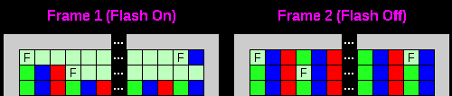
F= Flashing bit of 1
|
|
Many
Emulators don't bother to emulate FLASHing... QLAY2 doesn't
do it, and Q-Emulator doesn't seem to do it right except in
full screen mode... The latest versions of Zesarux DO seem
to do it well though...
That said, Falshing mode is pretty dumb anyway, so you're
not missing anything important if your emulator doesn't
support it!
|
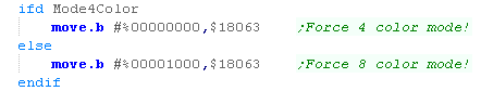
Selecting Screen Mode
When we want to change screen mode, we just set bit of
$18063 according to the mode we want...
a 1 will set 8 color mode... a 0 will ser 4 color mode! |
 |
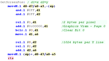
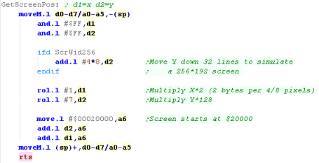
Calculating Screen position
When we want to calculate the
memory location of an X,Y position, it's pretty easy.
using an X position in 4/8 pixel blocks, and Y in lines we can
use following
Each 8 pixels uses 2 bytes, so we bit shift the X pos in D1 by
one bit.
Each line uses 128 bytes, so we bit shift the Y pos in D2 by 7
bits.
Then we add $200000 - the offset to the start ofthe screen. |
 |
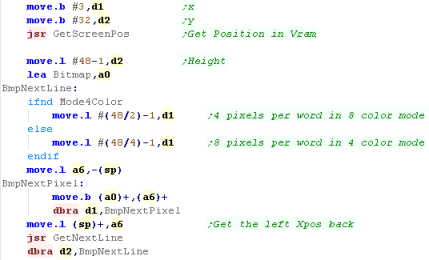
When we want to use this, we
just need to copy the bytes from our source (created by
AkuSprite) to the screen,
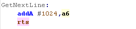
After each line we use GetNextLine to move down the screen to
start drawing the next line...
Because 4 color mode has twice as many pixels per byte, we
need to alter our line total in D1 depending on if we're in 4
color mode or not. |
 |
This routine will show a simple
bitmap...
We also have 'PrintChar' routines, these use a 1bpp font, and
show letters from a common font (used on all the systems) |
 |
The
Sinclair
QL's screen is pretty limited for a 16 bit machine, but
remember... it's an 68008 - which has an 8-bit data bus, so
technically it's and 8 bit machine... this means it's much
slower than an Amiga or similar... and you'll have to
optimize yout code more to keep the games fast.
The reduced graphics were probably and unavoidable sacrifice
considering the price-point and early release of the
machine. |
|
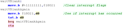
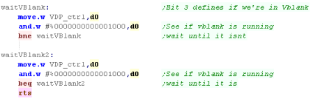
Vsync
We can use Vsync to slow down our game... by waiting for
Vsync, we can wait for the next screen redraw
If we want to test for Vsync (the start of screen redraw) we
need to use Port $18021... bit 3 will go high (1) when Vsync
starts... we need to write a 1 to that same bit at the same
port to clear the Vsync event...
Therefore, in effect we can write 255 to port $18021, then
read from $18021 until it's nonzero to get the Vsync event. |
|
|
7 |
6 |
5 |
4 |
3 |
2 |
1 |
0 |
|
| $18021
Read |
B |
M |
R |
X |
F |
T |
I |
G |
B=Baud
state,
M=Microdrive inactive, R=Rtc
state,
X=eXternal
Interrupt,
F=Frame
vsync,
T=Transmit
interrupt,
I=IPC
Interface interrupt G=Gap
interrupt
(microdrive)
|
| $18021
Write |
R |
F |
M |
X |
F |
T |
I |
G |
R=tRansmit
mask,
F=interFace
mask,
M=gap
Mask,X=reset
eXternal
Interrupt,F=reset
Frame
vsync, T=reset
Transmit
interrupt, I=reset
IPC Interface interrupt G=reset
Gap
interrupt |
 |
Lesson
P5 - Bitmap Functions on the Genesis
The Genesis is a Tile - Sprite based system... this means we
can't just plot data to the screen... we need to define our
bitmap data as tiles in vram, then set those tiles as visible
onscreen...
Lets give it a go! |
|
BitmapTest.asm |
|
|
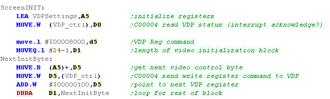
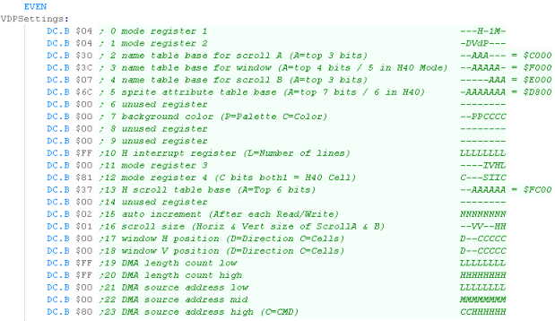
Setting up our screen
| We need to initilize our
screen, to do this we need to set some VDP settings... these
start with $8nvv - where n is the register number and vv is
the value for the register... we'll load these from the table
VDPSettings |
 |
We'll be using the values shown
for our tutorials...
you can change the values if you wish, but if you change
things like the name table positions, the tutorials will not
work correctly unless you also alter the code that draws
characters and tiles to the screen |
 |
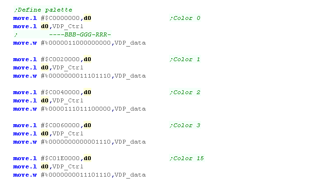
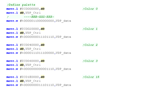
We're going to set up a simple
palette to get us started...
Basically, each color in the palette has two bytes defining
it's RGB value, but we're not going to go into more detail at
this stage, as we'll be covering it in more detail later. |
 |
| We've now done the basics... so we'll start the screen
display, then convert our 2 bit font to tiles in the tile
definitions. |
 |
|
Setting
Reg 16 to 01 defines a tilemap of 64x32 - we could define
one that's 32x32 or 64x64, but as our visible screen is
40x28 so 64x32 seems a good choice!
If you change it, or the memory address of Scroll A, then
you're going to have to change the rest of the code in
todays example! |
Defining Tile patterns
When we want to write data to
the VDP, we just write the data value to address $C00000
(vdp_data).... but first we need to select the VDP destination
address using $C00004 (vdp_ctrl)
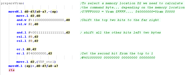
We'll need to select addresses from $0000-$C000 to define our
tiles and each tile takes 32 bytes.
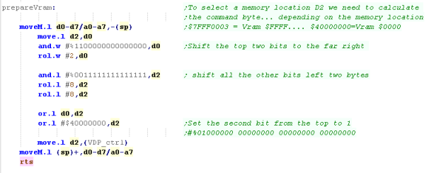
Unfortunately, because the VDP address select is designed to
be backwards compatible with the SMS, the bytes we have to
send to select the port are a little odd!... Effectively the
top two bits of the address are moved to the bottom two, and
the top two bits are set to %01...
you can see some how various sample VDP addresses convert to
address select commands in the table to the right.
|
Vram
Memory Address |
Byte
Command |
| $0000 |
$40000000 |
| $1000 |
$50000000 |
| $2000 |
$60000000 |
| $3000 |
$70000000 |
| $4000 |
$40000001 |
| $5000 |
$50000001 |
| $6000 |
$60000001 |
| $7000 |
$70000001 |
| $8000 |
$40000002 |
| $9000 |
$50000002 |
| $A000 |
$60000002 |
| $B000 |
$70000002 |
| $C000 |
$40000003 |
| $D000 |
$50000003 |
| $E000 |
$60000003 |
| $F000 |
$70000003 |
| $FFFF |
$7FFF0003 |
|
| Vram Address |
Possible Use |
| $0000 |
Pattern
definitions |
| $C000 |
Scroll
A
� Tilemap |
| $D800 |
Sprite
Attrib
table |
| $E000 |
Scroll
B
� Tilemap |
| $F000 |
Window
Map |
| $FC00 |
Hscroll
Table |
|
Selecting VDP
memory
is really confusing... but don't worry, we're going to
create a little function that will do all the work for us!
The reason it's so confusing is the Genesis was designed to
be backwards compatible with the Master system... that's why
the genesis uses a Z80 for it's sound chip - it can be
used as the main CPU for SMS support! |
|
To simplify sending data to the
VDP we'll create a command called 'PrepareVram'
This will calculate the correct address to write to within the
VDP |
 |
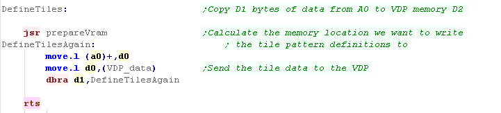
When we want to define tiles,
we'll just copy the tile data into the VDP...
We'll define the start of the tile definitions in A0, the
destination in vram in D2, and the bytecount in D1 |
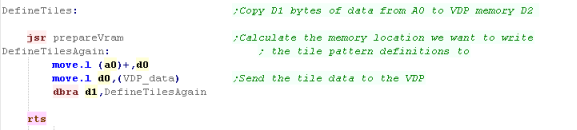 |
| When we want to transfer our
tile definitions to VRAM, we can just call this 'Define Tiles'
command. |
 |
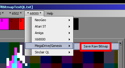
Of course, you'll need to
convert a bitmap into the correct format for the VDP... but
you can do this with my AkuSprite editor!
It's free and open source, and you'll find it in the
sources.7z |
 |
|
AkuSprite
editor
supports all the systems covered by these tutorials... and
It'll be extended to cover any systems added in the future.
It's only a basic program, but you can load bitmaps in via
the clipboard so you can use a more advanced eitor like
Krita to do the hard work |
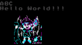
Getting our tiles on the screen
We've now got our 'Chibiko'
bitmap in vram as patterns, but we need to get it on screen...
the bitmap is 48x48 pixels... meaning it's made up of 6x6 (36)
tiles...
To show our bitmap on the screen we need to set the tiles in
the positions we want to the correct pattern numbers for our
bitmap! |
 |
We're going to define a command
called 'FillAreaWithTiles'
We'll pass it a Start XY position, a width and height, and a
start tilenumber (256 - the first 128 are used by our font)
The command will calculate and set the tiles to get our bitmap
onscreen! |
 |
We've defined our tile map as
64 tiles wide, and 32 tiles tall... each tile definition takes
2 bytes... this means each row of the tile map is 128 bytes...
Therefore, to calculate our memory address within VRAM, we use
the formula $C000+(Y*128)+(X*2) |
| F |
E |
D |
C |
B |
A |
9 |
8 |
|
7 |
6 |
5 |
4 |
3 |
2 |
1 |
0 |
| L |
P |
P |
V |
H |
T |
T |
T |
|
T |
T |
T |
T |
T |
T |
T |
T |
T=Tille
number
H=Hflip
V=vflip
P=palette
number
L=Layer (in front of /behind sprites)
|
We're going to merge our
calculation of the byte position in VRAM and our 'PrepareVram'
command to save CPU power,
For each line, we'll calculate the starting address of the
line and send the VRAM select command to the VDP
We'll then start writing our tile numbers to VRAM... The VRAM
address automatically increments after each write, so we don't
need to recalculate until we've completed the whole line, but
we do need to increment our tile number in D4
After each line we recalculate the memory position for the row
below,
We continue this procedure until the the bitmap is drawn to
the screen! |
 |
Of
course this is just a simple example... but you can use it
to create something better... Take a look at Grime
68000 if you want to see a more advanced example!
We've only looked at Tiles so far, but don't worry, we'll
look at sprites later! |
|
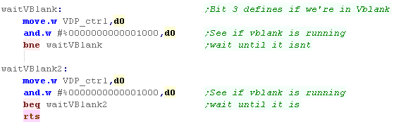
VBlank
We can use Vblank as a way of slowing down our game...
Vblank occurs when the screen restarts drawing, so happens 60
times a second (50 on PAL systems)
We can detect Vblank using bit 3 of data read from the Control
port, we just read in a byte and test it, if the bit is 1
we're in VBlank.
We can wait until Vblank starts, and ends to ensure our game
isn't running faster than 50fps. |
 |
 |
Lesson
P6 - Bitmap Functions on the Amiga
The Amiga is essentially a 'bitmap' based system, we allocate
an area of memory to be our screen data, and we can write data
into that area to get our pixels on the screen,
However there are some complexities to getting things working,
so lets learn how to make it behave! |
|
BitmapTest.asm |
|
|
The Amiga screen is essentially a bit-planed bitmap within 'Chip Ram'
(the built in memory of the Amiga - not upgrade memory)... we can
write bytes to this ram, and they will immediately appear on the
screen - but first we need to set the screen up!
Graphics on the amiga are controlled by the '
Chip
Registers' a set of memory mapped registers which control the
screen... in theory we could access these directly... but in practice
we need to use the "Copper" graphics CO Processor...
We give this a set of commands defining the screens location and shape
in ram!
Bitplanes and colors
The Amiga works in
'Bitplanes'... this is where each byte of data for the screen
contains a single bit of 8 pixels - called a bitplane...
4 of these bitplanes combined will allow us 16 colors...
The Amiga 500 supports up to 6 bitplanes, We can optionally
configure these bitplanes into 2 layers in parallax...
The Amiga can use up to 32 colors in a single layer (5
bitplanes) ... or have two 3 bitplane layers with 8 colors
each (odd numbered bitplanes will be layer 1, even numbers
will be layer 2)
In these tutorials we'll be defining one 320x200 layer of 16
colors (4 bitplanes)... this is because it will give good
'compatibility' with the Atari ST, and the other systems we're
covering in these tutorials.
|
8
pixels we want to set:
Bitplanes compared to nibbles
|
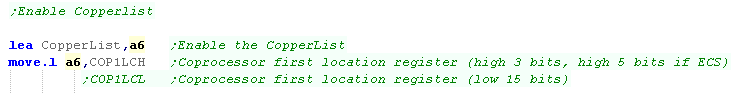
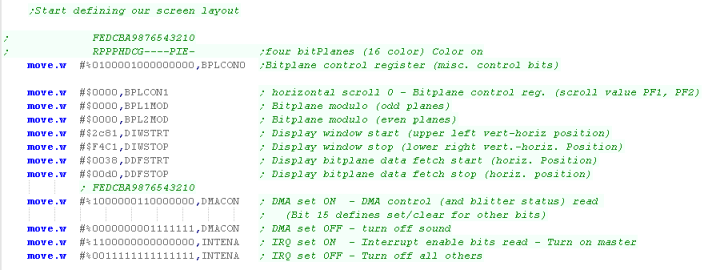
Copper list commands
We're going to need to use a copperlist to set up our screen...
Copperlist commands can set a chip register, or wait for a
particular screen position
| Word 1 |
|
Word 2 |
|
|
|
| F |
E |
D |
C |
B |
A |
9 |
8 |
|
7 |
6 |
5 |
4 |
3 |
2 |
1 |
0 |
|
F |
E |
D |
C |
B |
A |
9 |
8 |
|
7 |
6 |
5 |
4 |
3 |
2 |
1 |
0 |
|
Command |
Details |
| 0 |
0 |
0 |
0 |
0 |
0 |
0 |
n |
|
n |
n |
n |
n |
n |
n |
n |
0 |
|
D |
D |
D |
D |
D |
D |
D |
D |
|
D |
D |
D |
D |
D |
D |
D |
D |
|
Change setting |
n=
address to Change ($DFFnnn) D=new
data
for address |
| V |
V |
V |
V |
V |
V |
V |
V |
|
H |
H |
H |
H |
H |
H |
H |
1 |
|
v |
v |
v |
v |
v |
v |
v |
v |
|
h |
h |
h |
h |
h |
h |
h |
1 |
|
wait for pos |
V=Vops
H=Hpos v=Vpos
Compare
enable h=hpos
compare
enable |
The copperlist should end with an infinite wait '#$fffffffe'
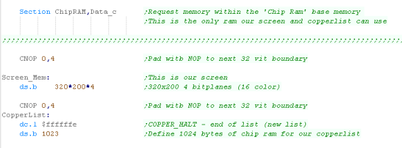
Setting up Chip Ram
We need our screen and the 'Copperlist' for the
co-processor to be contained within the 'Chip Ram'
To ensure this we need to define a 'ChipRAM'
section - the Assembler / Linker will create an
executable file, and the operating system will ensure this
area of the program is in the correct
We're also going to use the command 'CNOP
0,4'... this zero pads the area to a 32 bit boundary
- needed for the screen data
Now we have some memory, we can start setting up the screen! |
 |
|
'Chip
Ram'
in the Amiga is the basic ram of the machine (not add on
upgrades)... we need it to do tasks like Graphics and Sound
FX...
Our main code probably isn't running in Chip ram, so we
can't 'tag' our screen buffer in there - we have to declare
proper section, so the Assembler will build the correct
executable and the OS will give us our memory |
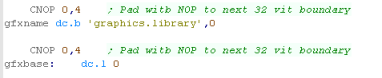
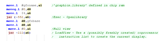
Setting up our screen
The first stage of setting up
our screen is calling the os, and opening the graphics library
...
we'll use this to turn on the screen, but we'll do all the
other screen config by directly manipulating the hardware
registers!
You can see the different libraries the Amiga has here
... and the full contents of the Graphics library here |
 |
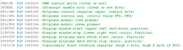
We're going do the basics of
defining the screen size, bitplanes and position.
we need to use the chip registers to do this (see here
for the full list)
We're going to set up our 320x200 16 color (4 bitplane) layer,
Next we'll set up the screen position
Finally we want to start the DMA control to handle the
screen...
we're now going to set up our copperlist that will define the
screen memory and colors!
|
|
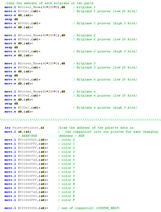
Setting up our copperlist
We need to define our
copperlist, the Coprocessor will use it to draw each frame of
our screen.
As mentioned before, the copperlist commands are made up of
two words per command,
The first word (2 bytes) is a register number... for
example $00e2 is $DFF0E2
The second word (2 bytes) is the new value for the
command.
First we'll define the memory location of the 4 bitplanes that
make up our screen - they'll be 8000 bytes apart (40x200)
Then we'll define our starting color palette... we'll also
remember the memory position of the palette definitions, as we
can use it later to change our colors.
The last commands is a command to wait forever ($fffffffe) ...
the list will automatically restart when the next screen
redraw starts.
|
 |
When we've defined our copperlist, we load the address of the
copperlist into the pointer of the Chip Ram - our screen is
finally set up! |
 |
|
The
example here is just creating a single plane, you could have
more colors, or more planes with a more advanced set up, but
that's beyond the scope of these tutorials - but feel free
to play around if you want! |
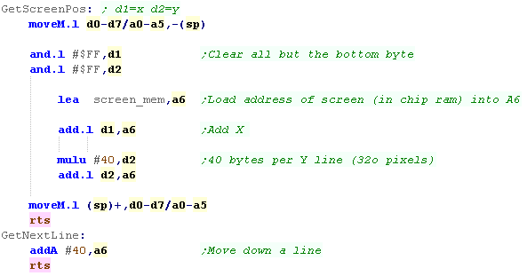
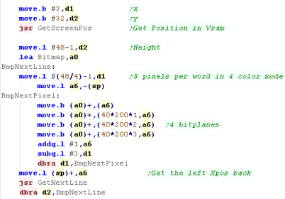
Getting our bitmap data to the screen
Our screen is split into
4 bitplanes, and as the screen is 320 pixels wide (40 bytes)
and the screen is 200 lines tall, then each bitplane will be
8000 pixels apart.
Of course, if we want to set the color of a pixel, we'll have
to set all these bitplanes, and we'll see that in our code |
| Offset
from
Screen_Mem |
Bitplane Number |
0
0 |
Bitplane 1 |
40*200*1
8000 |
Bitplane 2 |
40*200*2
16000 |
Bitplane 3 |
40*200*3
24000 |
Bitplane 4 |
|
We can see this mimicked in our
bitmap copying code...
The byte data of the bitmap are in bitplane format (exported
by my AkuSprite Editor)
4 consecutive bytes bytes are copied to each bitplane.
We use the GetScreenPos to calculate the correct memory
position from a X,Y position (where X is in Bytes, and Y is in
lines)
We also use GetNextLine to move down a line at the end of each
line of our bitmap |
 |
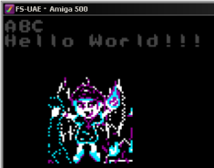
| The bitmap will be shown to the
screen at the position we specified! |
 |
Want to
convert a bitmap for use on the Amiga? The Free & open
source AkuSprite Editor can do it for you!
It's included in the sources.7z, so go get it if you want! |
|
Calculating screen co-ordinates
Setting up the screen was hard,
but Calculating a screen position is easy.. all we need
to do is multiply our Ypos by 40 (the width of the
screen) and add X , and the base of the screen.
Moving down a line is also easy, we just add 40 to the current
position! |
 |
|
Of
course, calling a routine to move down a line is a pretty
lousy to do things if you're just doing an Amiga game, you
should just put that ADDA straight in the loop!
The reason we do the call is we're supporting lots of
machines with the common drawing code... THEN it makes
sense!
|
Testing for Vblank
If we want to slow our game down, a good way is to wait for
Vblank (The start of screen redraw)
this will cap our game to 60/50 hz, and keep our game speed
under control
We can test for Vblank on the Amiga by testing $DFF004 (VposR) |
 |
Common Data format for Joypad controls used by these tutorials
On the Z80 We used to read in the buttons and fires into a
single byte... on the 68000 systems we're going to keep the
same format for ULDR Fire1+2 and start... but we'll also
extend into a second byte for any extra fire buttons we
have...
for each bit, a 1 means the button is up (unpressed)
a 0 means the button is down (pressed)
We'll load player 1's joystick data into D0... and player 2's
into D1 |
| Bit |
F |
E |
D |
C |
B |
A |
9 |
8 |
|
7 |
6 |
5 |
4 |
3 |
2 |
1 |
0 |
| Meaning |
- |
- |
- |
F8 |
F7 |
F6 |
F5 |
F4 |
|
Start |
F3 |
F2 |
F1 |
Rgt |
Lft |
Dn |
Up |
|
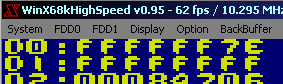
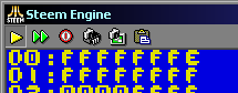
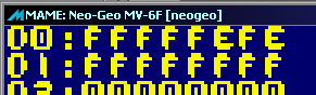
| Our test program is very simple, all it does is read in the
two controllers, and show the value of the registers to the
screen. |
 |
|
The
data
we're producing here is not just consistent across 68000
systems, but also the 6502 and Z80 systems in these
tutorials... this was used as part of Grime 68000 to make
converting the game easier. |
Ports relating to the Joypad
We're going to use 3 ports to access the two players
buttons...
$E9A001 reads player 1, $E9A003 reads player 2
$E9A005 selects which buttons we're reading in
|
| Address |
Purpose |
Bits |
Notes |
| $E9A001 |
Joystick
#
1 |
|
Data
from
Joy 1 |
| $E9A003 |
Joystick
#
2 |
|
Data
from
Joy 2 |
| $E9A005 |
Joystick
Control |
--MM---- |
00
Select
Normal / 11 alt keys |
|
| Depending on the bits we write
to $E9A005, the data we get back from the two Joystick ports
will either return the basic joystick buttons, or the extra
buttons of a genesis joypad. |
Byte written to
$E9A005 |
Purpose |
$E9A001
/ $E9A003
Data Bits |
| %00000000 |
Basic
Buttons |
%-21-RLDU |
| %00110000 |
Extra
Buttons |
%-S3-M654 |
|
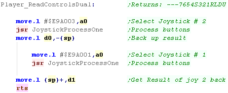
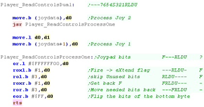
Lets get the data!
We're going to define a
function called "Player_ReadControlsDual"
This will read both joysticks, we load the address of the
joystick we want to read into A0... then we call
JoystickProcessOne
The JoystickProcessOne function will process all the buttons
from the port in A0... and return the buttons in D0 |
 |
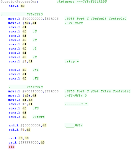
To select the basic controls,
we write $0 to $E9A005... now we just
need to read in from (A0)... we need to shift the bits around
a bit to get them in the same format as the other systems...
Now we do the same with the extra buttons, we write %00110000
to $E9A005... and then we bit shift all the extra
buttons in the correct positions...
finally we OR all the unused bits to 1, to make the returned
data consistent. |
 |
The Theory!
We're going to need to turn on the Joystick, and add an 'event
handler' to the joystick, to read in the data from the Joystick.
We're going to need some TRAPS to call systems functions, We'll need
the BIOS trap (Trap #13) to turn on the joystick, and XBIOS trap (trap
#14) to get the vectors, so we can patch in our joystick handlers.
You can see all the Traps and options
here,
The IKBD commands are
here, and
the vectors that are returned are
here,
This is just for reference, you won't need these to get things working
today
On our Atari ST we'll consider Port 1 to be the 1st joystick, and Port
0 to be the 2nd (as we'll assume it usually has a mouse)
Common Data format for Joypad controls used by these tutorials
On the Z80 We used to read in the buttons and fires into a
single byte... on the 68000 systems we're going to keep the
same format for ULDR Fire1+2 and start... but we'll also
extend into a second byte for any extra fire buttons we
have...
for each bit, a 1 means the button is up (unpressed)
a 0 means the button is down (pressed)
We'll load player 1's joystick data into D0... and player 2's
into D1 |
| Bit |
F |
E |
D |
C |
B |
A |
9 |
8 |
|
7 |
6 |
5 |
4 |
3 |
2 |
1 |
0 |
| Meaning |
- |
- |
- |
F8 |
F7 |
F6 |
F5 |
F4 |
|
Start |
F3 |
F2 |
F1 |
Rgt |
Lft |
Dn |
Up |
|
| Our test program is very simple, all it does is read in the
two controllers, and show the value of the registers to the
screen. |
 |
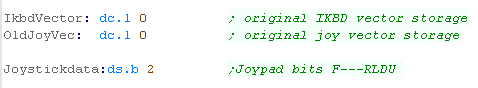
Defining Data
We're going to define a few bytes of data for our use in
this example... two longs to back up the settings of the Bios
(we won't actually need them, but you might if you want to
undo things)...
We also need two bytes... one for each joystick's data during
the read operation |
 |
Our
principle is simple, get the bios to run our program code...
and use that code to copy the joystick data into a buffer...
When we want it, we'll sort the data into the format we
need. |
|
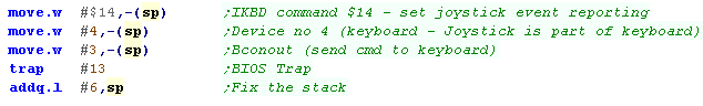
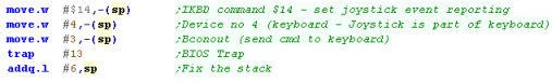
Trap Attack! Getting the bios to do our bidding!
We're going to tell the BIOS that we want to use the
Joystick... we'll need Trap #13 to send a command to the
bios...
We want to use Command #3 to send a command via Bconout... we
push #13 as a word onto the stack before the trap command...
BUT... the BconOut also needs a device number and a character
to send...
We want device #4 - which is the keyboard (which the joystick
is connected to)... we push this onto the stack too...
We want to send #$14 (#20) to the keyboard - this command
tells the keyboard to send events (Every joystick
movement is automatically returned.)
When we've done all this, and the Trap #13 finishes, we need
to fix the stack, so we add 6 to the stack, to remove the 3
words we pushed
|
|
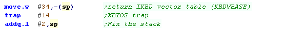
Now we're going to use the XBIOS... which uses Trap #14...
we want to use command #34 'KbdVBase' - so we push #34
onto the stack as a word...
|
 |
KbdVbase returns a vector table in D0 - this is a table of
calls for various purposes - we want to change entry 6...each
is a long so 6x4=24
We'll back up the address of the vector table,
Next We're going to back up the current Keyboard vector
(though in our code we won't ever undo it)...
Finally we'll copy the address of our new joystick code
(JoystickHandler) to the 24'th entry in the table...
This means our code can get the Joystick data. |

|
|
Now we've
made the Bios do what we want, our Joystick handler will be
called automatically, and will grab the data for us...
That's all we need the Bios for... now we're in control
again!
|
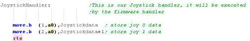
Our Joystick Handler!
Because we patched it into the
Vector table, Our Joystick handler will be called by the
firmware, when it does, A0 will point to the data we
want...
We're going the data from both joysticks into our 2 byte
'Joystick data' cache... we'll process that when the game
actually wants to know what keys are pressed |
 |
Processing the joysticks
When it comes to processing the
joysticks, we'll transfer the byte from the buffer for each
joystick into D0, then we'll run 'ReadControlsProcessOne'...
this will shift the bits from the Atari ST Format (F---RLDU)
to our common format (---FRLDU)
We do this by shifting the bit we want to move into eXtend,
then shifting things around, and putting it back in the
position we want...
We do this twice, moving Player 2's data into D1 |
 |
|
Lesson
P9 - Joystick Reading on the
NeoGeo
The Joystick on the NeoGeo makes things easy for us!
There are two ports, one contains Select/Start buttons,
and the other contains the joypad settings.
We can just read in from these to get the directions selected
on the Joypad. |
|
|
|
|
Common Data format for Joypad controls used by these tutorials
On the Z80 We used to read in the buttons and fires into a
single byte... on the 68000 systems we're going to keep the
same format for ULDR Fire1+2 and start... but we'll also
extend into a second byte for any extra fire buttons we
have...
for each bit, a 1 means the button is up (unpressed)
a 0 means the button is down (pressed)
We'll load player 1's joystick data into D0... and player 2's
into D1 |
| Bit |
F |
E |
D |
C |
B |
A |
9 |
8 |
|
7 |
6 |
5 |
4 |
3 |
2 |
1 |
0 |
| Meaning |
- |
- |
- |
F8 |
F7 |
F6 |
F5 |
F4 |
|
Start |
F3 |
F2 |
F1 |
Rgt |
Lft |
Dn |
Up |
|
| Our test program is very simple, all it does is read in the
two controllers, and show the value of the registers to the
screen. |
 |
Hardware Ports
Reading Joysticks on the NeoGeo requires reading from 3 memory
addresses... one for the start buttons, and two for each of the two
main Joysticks.
We actually have a choice - we can read in from the hardware directly
using the $3x0000 addresses, of via the bios updated ones,
The only real difference is that if we read directly from the
hardware, then
1
will be a button that is up, and
0
will be down...
Alternatively, if we read from the bios, it's backwards so
0 will be a button
that is up, and
1
will be down...
|
|
|
Bits |
| Address |
Purpose |
Method |
7 |
6 |
5 |
4 |
3 |
2 |
1 |
0 |
| $10FDAC |
Sel/Start |
Bios |
P4-Select |
P4-Start |
P3-Select |
P3-Start |
P2-Select |
P2-Start |
P1-Select |
P1-Start |
| $380000 |
Sel/Start |
Direct |
AES/MVS |
WriteProtect |
CardInserted
2 |
CardInserted
1 |
P2-Select |
P2-Start |
P1-Select |
P1-Start |
| $10FD96 |
Player
1 |
Bios |
D |
C |
B |
A |
Right |
Left |
Down |
Up |
| $300000 |
Player
1 |
Direct |
D |
C |
B |
A |
Right |
Left |
Down |
Up |
| $10FD9C |
Player
2 |
Bios |
D |
C |
B |
A |
Right |
Left |
Down |
Up |
| $340000 |
Player
2 |
Direct |
D |
C |
B |
A |
Right |
Left |
Down |
Up |
|
The NeoGeo
AES also has coinslots, these can be read in from $320001
Bits 0,1,3,4 are coins 1-4... bit 3 is the 'service button'
You'll need these if you're trying to crete an arcade game! |
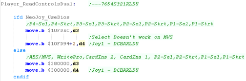
Getting the data
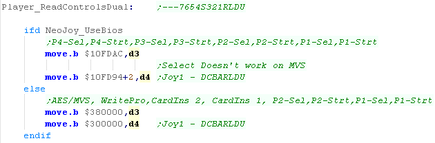
| As it's fairly easy, The example code today will support
reading from either the BIOS variables, or the direct ports,
to select the Bios we just need to define NeoJoy_UseBios, and
the code will use the bios ports instead. |
 |
First we're going to handle Joystick 1 - we'll load it's
data into D4...
We're also going to need Joystick 1's Start button, all the
start buttons are in the same port, so we'll load them into D3 |
 |
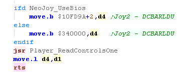
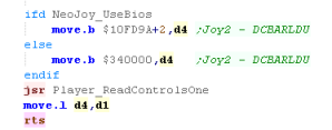
As both joysticks use the same layout, We'll use a common
function 'Player_ReadControlsOne' to shift the bits around
into the order we need... we'll run it first for joystick 1,
and store the result in D0...
We'll take a look at what the function does in a moment. |
 |
We're going to do the same now for Player 2.
We don't need to read the Start buttons in again, as the
second players start still remains in the byte in D3 we read
before. |
 |
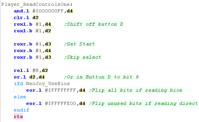
We using the 'Player_ReadControlsOne' function to convert
the data for both players...
When this function starts, D4 will contain the joystick fires,
First we need to shift button D out into D2 - we'll need it
later, but we need to put the Start button into Bit 7
We'll shift the Start button into D4, we'll also 'skip'
the select button - The AES arcade machines do not have it
anyway.
Now we want to move that D button into our register - so we
shift it 8 bits to the left, and OR it into the correct
position in D4...
The last thing to do is ensure any unused bits are set to 1 -
if we're using the BIOS we need to flip all the bits, but if
we're not then we only flip the unused ones. |
 |
We're only
using two joysticks in these tutorials, but if that's not
enough you can theoretically have another have another 2
These are read in via the bios from $1OFDA2, $10FDA8...
Whether the emulators will actually support them in
another matter! |
|
|
Lesson
P10 - Cursor reading on the Sinclair QL
The Sinclair QL supports up to 2 joysticks via the CTL ports
(CTL1 and CTL2)... but these actually connect to the keyboard
keys!
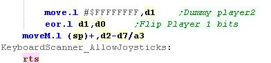
Joystick 1 maps to the Cursor keys, and space for fire...
We're going to read the cursors, and use them as the same
joystick buttons on our other systems. |
|
JoyTest.asm |
|
|
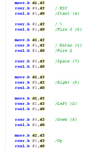
Keyboard Layout
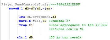
Reading in from the keboard has
to be done with Trap 1 - command 9
We have to send a sequence of command bytes - with byte 6 as
the row number - the trap will return a byte in D1 - with a
bit high when the button is down.
An example of the command is shown to the right - this example
will read in row
1
Joystick 1 (CTL1) uses Up, Down, Left,
Right and Space
Joystick 2 (CTL2) uses F4, F2, F1, F3
and F5 |
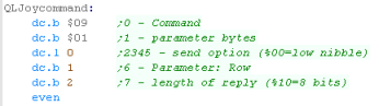
lea keycommand,a3
move.b #$11,d0
Trap #1
keycommand:
dc.b $09 ;0
- Command
dc.b $01
;1 - parameter bytes
dc.l 0 ;2345 - send option (%00=low nibble)
dc.b 1
;6 - Parameter:
Row
dc.b 2 ;7 - length of reply (%10=8 bits)
|