

Why IM2?
The SAM coupe can use IM1, as we can page
in ram to the &0038 address, but there's an issue!
The screen ram takes a whopping 24K, two thirds of one of the pagable banks. If we want to page in pattern graphics into the low bank (&0000-&7FFF), to draw to the screen in the high bank (&8000-&FFFF)
Where will our interrupt handler be?
The screen ram takes a whopping 24K, two thirds of one of the pagable banks. If we want to page in pattern graphics into the low bank (&0000-&7FFF), to draw to the screen in the high bank (&8000-&FFFF)
Where will our interrupt handler be?
We could disable interrupts, while we
copy graphics, but missed interrupts on the SAM never occur, so our
music would slow down.
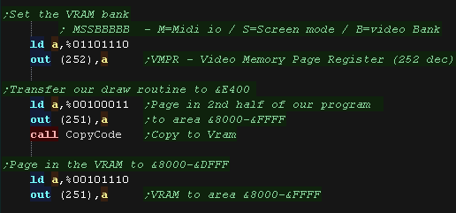
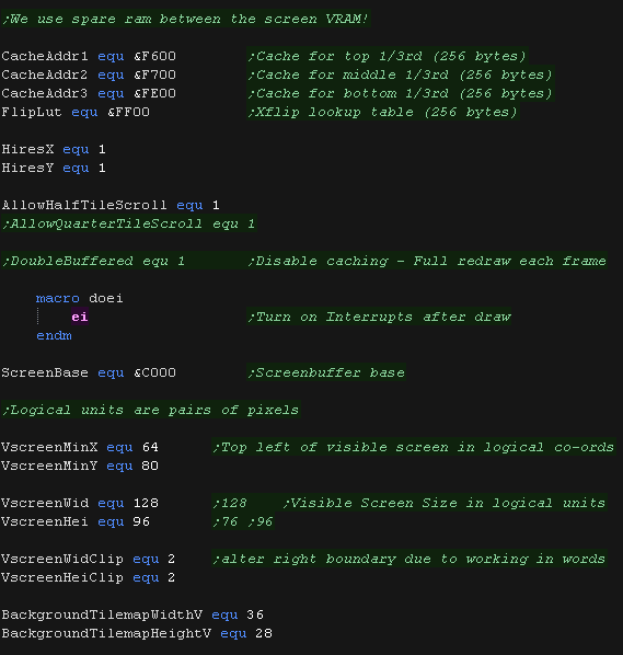
The solution we'll use it to set up an
IM2 block at the &E000-&E200 range (Vram uses
&8000-&DFFF). Our interrupt handler will page the music back
in (and out) to the &0000-&7FFF range
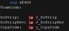
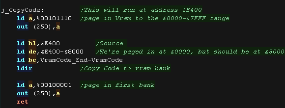
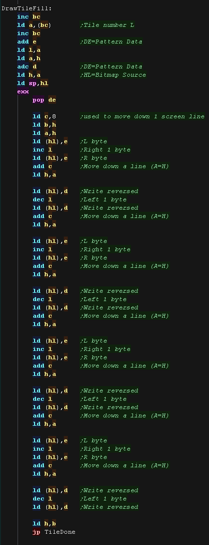
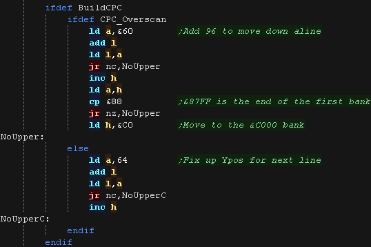
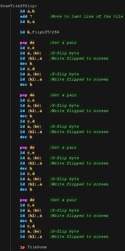
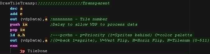
We'll then copy our drawing routines to
&E400 - This allows the drawing routines to page in more bitmap
patterns into the &0000-&7FFF range to copy to Vram.
Interrupt Mode 2
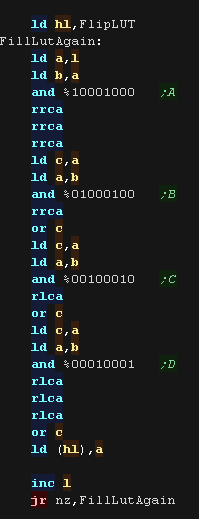
In this mode an address is formed by
taking the top byte from the R register, and the bottom byte from the
interrupting device.
A 16 bit word is read from that address, and that address is called.
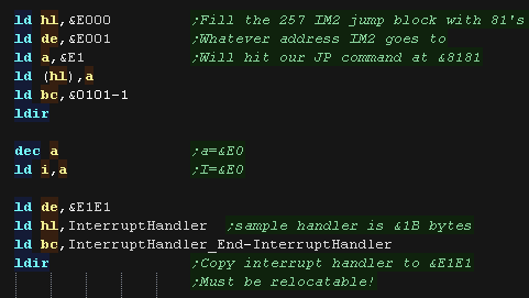
We can't effectively predict what the bottom byte will be, so we need to define a block of 257 bytes which all point to the same address.
The common solution is to fill memory addresses $8000-$8101 with the value $81. The effect of this is that all interrupts will call to $8181, and it's at that address we put the code for (or jump to) our actual interrupt handler.
This is not very convenient, and IM 1 is far more useful. But on systems like the Spectrum, where low memory (Address &0038) is ROM, then this is the best solution for us.
A 16 bit word is read from that address, and that address is called.
We can't effectively predict what the bottom byte will be, so we need to define a block of 257 bytes which all point to the same address.
The common solution is to fill memory addresses $8000-$8101 with the value $81. The effect of this is that all interrupts will call to $8181, and it's at that address we put the code for (or jump to) our actual interrupt handler.
This is not very convenient, and IM 1 is far more useful. But on systems like the Spectrum, where low memory (Address &0038) is ROM, then this is the best solution for us.
The Interrupt Handler
| We use a LDIR to fill the 257 bytes with &E1E1 We load I with &E0 - as our IM2 block starts at &E0xx We as our IM2 block contains &E1E1, we copy our interrupt handler to address &E1E1. The area &E102-&E1E0 is actually free for use (eg ram vars/stack) |
 |
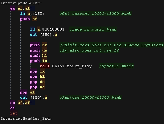
| The interrupt handler must be relocatable, meaning we can
use JR, but not JP or CALL (the Call to ChibiTracks_PLAY is fine, as the paging operation moves this to the right address) port 250 controls the low bank, we remember the current setting, then page in the music bank (%00100001) so we can play it Our interrupt handler updates the music. Chibitracks uses HL,BC,DE IX and AF only |
 |
| We need to switch on IM2 and enable interrupts | 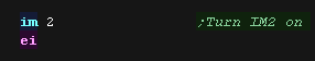 |
ChibiTracks
| To use ChibiTracks, we need to include the modules of the
music player, We also need the platform specific "Chibisound Pro" sound driver. |
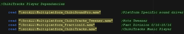 |
| We need to have a ChiBiTracks music file to play. |
 |
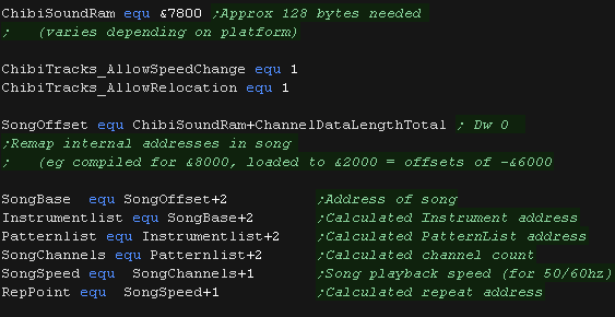
| We have two options 'Allow Speed change' allows us to change
the speed of our song. This is useful to keep the song playing
the same speed on 50hz and 60hz screens. NOTE: Whether this
will work effectively depends on if the speed was
pre-multiplied on export (faster playback, but stops this
function working) AllowRelocation allows the binary to be loaded at any memory address, not just the one 'compiled' into the binary at export time - while disabling this will save a little speed/memory it's recommended you keep this enabled! We need to allocate up to 128 bytes of memory for ChibiSoundPro, and ChibiTracks player. We define pointers to the ChibiTracks variables within this ram. |
 |
| Before we play anything we need to init the ChibiSoundPro
Driver. To start our song, we set SongBase to point to the music file we want to play, and call StartSong - we do this any time we want the music to change |
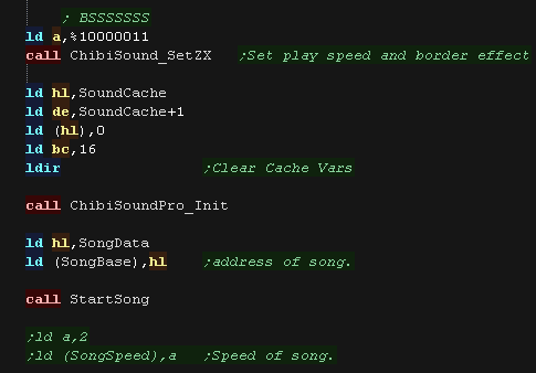 |
| All that's left is to execute the PLAY routine to update the
playing music. ChibiTracks uses AF,BC,DE,HL and IX... it does not use IY or shadow registers. |
|