Learn Multi platform PDP11 Assembly
Programming... With Octal!

|
Don't like to read? you can learn while you
watch and listen instead!
Every Lesson in this series has a matching YOUTUBE video... with
commentary and practical examples
Visit the authors Youtube
channel, or Click the icons to the right when you see them
to watch the Lessons video! |
 |
Before the ZX Spectrum, the CPC and
Nintendo, computing was literally a 'bigger' thing... the PDP-11
by DEC was an early computer...
Impressively advanced for it's time, it's programming language
resembles the 68000, and some of it's other design ideas can be
seen in other processors today.
The front of the PDP unit is lit up with LED's and covered in
switches... these aren't just a sci-fi prop though, the PDP panel
can be used as a hardware monitor and debugger, allowing any
address in the CPU's memory to be read and altered.... in fact
booting the PDP-11 may require setting many of these switches to
program a 'boot sequence' into ram.
|
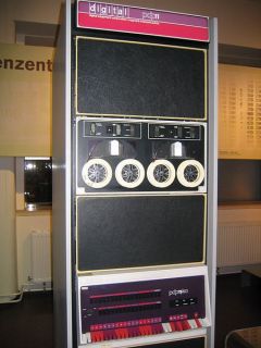
A PDP/40
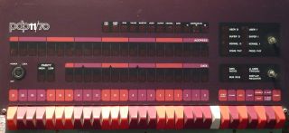
The PDP-11 front panel. |
Useful Resources:
ChibiAkumas Tutorials
PDP-11 Simple Samples
PDP-11 Multiplatform Specific Lessons
PDP-11 Platform Specific Lessons
PDP-11 SuckShoot Series

What is the PDP and what
the heck is 'Octal'?
The PDP-11 is an 16-Bit processor - in the 1970s it was classed as
a 'MiniComputer'... the CPU unit was around the size of a
microwave, and when connected to disk drives and other hardware,
the whole computer was the size of a single 'rack'
Octal is a numbering system known
as 'Base-8' - it uses digits 0-7, effectively grouping digits
from sets of 3 bits.
Octal allows binary to converted to
digits, without using any extra 'letters', allowing for easier
display and usage on conventional hardware like calculators.
If we're going to use the PDP-11 we
need to get used to octal, as that's how all the documentation
is written... fortunately, because it only uses 'digits' it
won't be too strange, and we can mostly not worry about it!
While Octal is the 'norm' in PDP,
Our Assembler can use other formats with the following syntax.
Base
|
Symbol
|
Alternate |
Example
|
Radix command |
| Binary |
^b
|
|
#^b101 |
.RADIX 2 |
| Octal |
(default)
|
^o |
#777 |
.RADIX 8 |
| Decimal |
.
|
^d |
#987. |
.RADIX 10 |
| Hexadecimal |
^x0
|
|
#^x0FF |
.RADIX 16 |
| Ascii |
'
|
|
#'A |
|
^FF seems to work for HEX as well.
the PDP 11 is a Little
Endian system... Low bytes are stored at even numbered
addresses, and High bytes are stored at odd addresses
|
| Oct |
Dec |
Hex |
Binary |
| 1 |
1 |
1 |
1 |
| 2 |
2 |
2 |
10 |
| 3 |
3 |
3 |
11 |
| 4 |
4 |
4 |
100 |
| 5 |
5 |
5 |
101 |
| 6 |
6 |
6 |
110 |
| 7 |
7 |
7 |
111 |
| 10 |
8 |
8 |
1000 |
| 11 |
9 |
9 |
1001 |
| 12 |
10 |
A |
1010 |
| 13 |
11 |
B |
1011 |
| 14 |
12 |
C |
1100 |
| 15 |
13 |
D |
1101 |
| 16 |
14 |
E |
1110 |
| 17 |
15 |
F |
1111 |
| 20 |
16 |
10 |
10000 |
| 100 |
64 |
40 |
1000000 |
|
The PDP-11 and
UKNC content on this site wouldn't have been possible without the
help of 'aberrant'... who's also working on a UKNC port of
Chibiakumas!... not only is it an impressive feat, but the code is
incredibly well commented, and worth looking at for UKNC insights
You can check out aberrant's work here!
|
 |
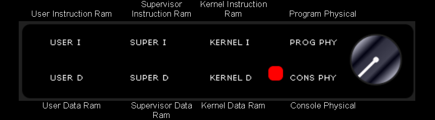
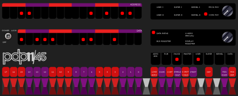
Using The PDP-11 Front panel
The PDP 11 has an advanced front panel, which effectively can
operate as a debugger, and is also able to program words of data
into memory... The
There are 18-22 SWITCHes numbered
0-17/21 - these are used to set a value to be used as an address
or as a value to store. the ADDRESS leds show the address being
set or probed, the DATA leds show the value at an
address/register
You can try out the PDP interface online... Here! |
 |
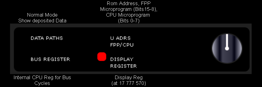
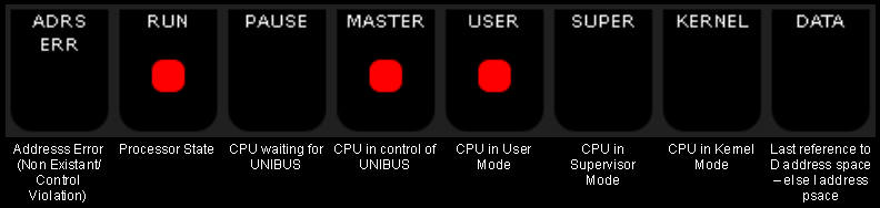
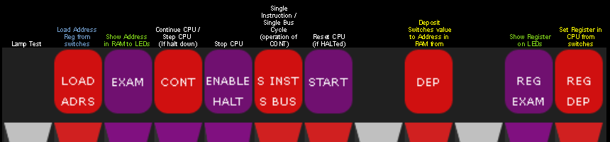
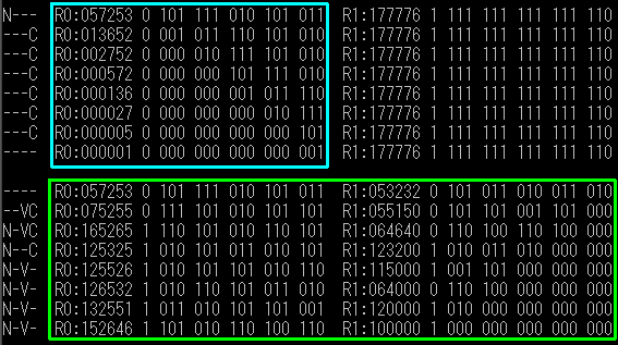
The other switches and leds have the
following functions:
The PDP-11's registers are ALL 16 bit.
Register
|
Details
|
Notes
|
R0
|
|
|
R1
|
|
|
R2
|
|
|
R3
|
|
|
R4
|
|
|
R5
|
LK |
Often Used to remember the return address during calls |
SP (R6)
|
SP |
Stack pointer |
PC (R7)
|
PC |
Used to remember running address |
If an Even register number (R0,R2,R4) is used for certain commands
(for example MUL)- the register and it's following will be used as
a 32 bit pair when the result is returned
|
|
Flags: -------- PPPTNZVC
|
Name |
Meaning |
| - |
unused |
|
| P |
Priority |
|
| T |
Trap |
|
| N |
Negative |
1=Negative |
| Z |
Zero |
1=Result Zero |
| V |
Overflow |
|
| C |
Carry |
1=Carry |
Unlike many CPUs, the flags on the PDP-11 are not stored in a
register, but are stored at memory address 777776-7 (in octal). |
The PDP-11 Addressing Modes
The PDP-11 has 8 different addressing modes... many are similar to much
later systems... in addition it has 4 'effective modes' which are defined
by using Reg 7 as a parameter
'Deferred' addressing is known as indirect
addressing on other systems
| Octal Representation |
Mode |
Description |
|
Sample Command |
68000
Equivalent |
effective result |
0 R
|
Register |
Value is taken from Registers itself |
Rn |
|
|
R |
1 R
|
Register Deferred |
Value is taken from address in register |
(Rn) or @Rn |
|
(Rn) |
|
2 R
|
Auto Increment |
Value is taken from address in register.... register increased
by bytes read |
(Rn)+ |
|
|
(Rn+) |
3 R
|
Auto Increment Deferred |
Value is taken from address at address in register.... register
increased by 2 |
@(Rn)+ |
|
|
((Rn+)) |
4 R
|
Auto Decrement |
Value is taken from address in register.... register decreased
by bytes read |
-(Rn) |
|
|
|
5 R
|
Auto Decrement Deferred |
Value is taken from address at address in register.... register
decreased by 2 |
@-(Rn) |
|
|
|
6 R
|
Indexed |
Value is taken from address in register + a fixed number |
n(Rn) |
|
(2,R2) |
(Rn+n) |
7 R
|
Indexed Deferred |
Value is taken from address at address in register + a fixed
number |
@n(Rn) |
|
|
((Rn+n)) |
2 7
|
Immediate |
Fixed numeric value |
#n |
|
#n |
|
3 7
|
Absolute |
Value from fixed address |
@#A |
|
A |
|
6 7
|
Relative |
Value from relative address |
A |
|
|
|
7 7
|
Relative deferred |
Value from address in address |
@A |
|
|
|
MACRO-11
Macro-11 is the Assembler that is used by RT-11... Macro-11 is case
insensitive, it also only uses the first 6 characters of labels and
symbols... this limit extends to file names -which must be 6 characters or
less... eg 123456.MAC or ABCDEF.asm
We can complement (flip the bits) of a constant with ^C eg #^C123
Missing commands
| AND |
We don't have an AND command, but we can fake one, we flip all
the bits of our register, and use BIS (OR)
Here is the equivalent of AND #7 |
bic #177770,r0 ;effecitive AND #7
or
com R0 ;flip bits
bic r0,r1 ;clear |
CALL
RETURN |
We need to specify a register to use with calls
|
JSR PC,\addr
RTS PC
|
PUSH reg
POP reg |
Use AutoInc and AutoDec
|
MOV \reg,-(SP)
MOV (SP)+,\reg
|
|
|
|
|
|
|
Lesson
1 - Getting started with PDP-11!
For our PDP-11 development we'll be using R11 as an
assembler , and "UKNC back to life" as an emulator...
The UKNC is PDP-11 compatible (we can also run the tests on R11
itself)
There's a video of this lesson, just click the icon to
the right to watch it -> |
 |
 |
|
|
Character Limits: The joy of 6!
MACRO-11 is limited in many places to 6
characters... this is especially true in filenames... for labels and
symbols we can use more letters, but only the first 6
will be used - the rest will be ignored.
You will notice we do use longer labels in many
cases in these tutorials - this is to give the functions easy to
understand names.
Please bear in mind that the assembler we're using only processes
the first 6 |
 |
Structure of an ASM (.MAC) source
file
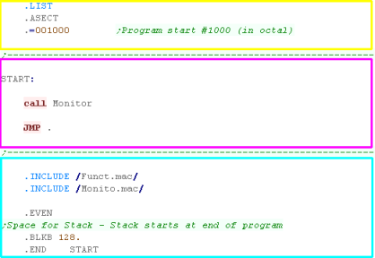
Lets look at a simple file (Min.MAC)
we have a header - Our program is defined
to start at #1000 in octal
In our body we're running a simple monitor
program - this is where you would put your code
In our footer we're including some useful
files (with a .INCLUDE statement), we're then defining a block of
128 bytes - this is for the stack, which will default to the top
of our program area on R11
MACRO-11 files often have the extension .MAC rather than .asm |
 |
 |
Notice the
JMP . (full stop)? - A full stop in Macro-11 is the same as * in
other systems, it returns the current line address..
So Jmp . is effectively an infinite loop.
|
Loading Values
WE have 6 general purpose (R0-5)registers we can use for
whatever we want,
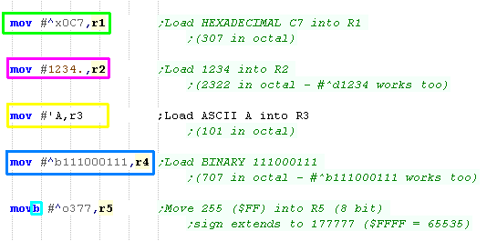
Lets look at the MOV command - it move a
value into a register
When we set a register, our source is on the
left, and the destination is on the right
This is a 16 bit command, the value will be two bytes, and by
default the number will be in OCTAL - #377 in octal is 255 in
decimal |
 |
| The register will be loaded with the value |
 |
By default we're specifying Octal, but we can specify other
values...
We can specify Decimal by putting a . at
the end of the number (or ^d at the start)
We can use Hex by putting ^x at the start
we can use ascii by putting ^' at the
start (we don't need the second ')
By default we're set to Octal (Base 8 / Radix 8) but we can force
octal with ^o
All the previous examples loaded a 16 bit value, but we can load
an 8 bit value by putting a B at the end of
MOV... the byte will be sign extended to a word (bit 7 will fill
bits 8-15 |
 |
| Here are the results! - note B5 was sign
extended, filling all the unused bits with 1's |
 |
By default
PDP-11 works in 16 bit, but many commands can have B tagged on
to the end to work in bytes...
Check out the cheatsheet to see all the details of the commands.
|
|
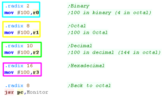
If we don't want to default to octal when we specify a # number,
we can do so with the .RADIX command
This changes the base as we require, we can always override the
base with the ^ commands we already looked at.
We can use Binary, Octal,
Decimal or Hexadecimal
Although it's tempting to default to HEX or DEC - we'll stick with
OCTAL in these tutorials - as it's how the systems was designed. |
 |
| here is the result |
 |
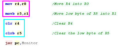
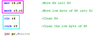
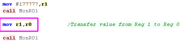
We'e looked at moving 'immediate' values (numbers with a # in
the command) - but we can also transfer values
from one register to another
We can also load zero with the CLR (clear)
command - this uses less memory than MOV #0,r4 |
 |
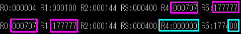
| Here are the results |
 |
INC and DEC
Just like the CLR command can quickly set a register to Zero -
we'll frequently want to take a register and add 1 or subtract 1
We'll need this for loop counters, reading data, and plotting
pixels to a screen... well we have special commands to do this INC
and DEC
by default INC and DEC
are 16 bit, but as before we can use INCB and
DECB |
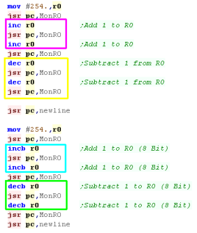 |
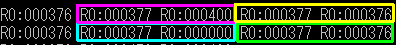
When we did the INC the word value up by two... when we did the
DEC it reduced again...
When we did INCB - the Byte went up, but when it went over #^o377
(Decimal 255) it rolled back to zero because 255 is the limit of
the byte... the DECB commands had the expected effect |
 |
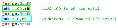
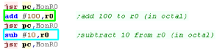
ADD and SUB
Of course,we can ADD and SUBtract other values!
We just specify the ADD/SUB with two parameters , the immediate
value or register on the left , and the destnation register on the
right |
 |
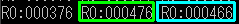
| Here are the result |
 |
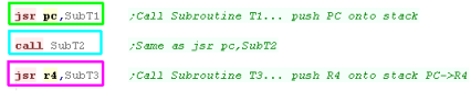
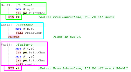
JSR and CALL / RTS and RETURN
The JSR and RTS functions on PDP-11 perform CALLS (Jump To
Subroutine) and RETURNs (Return from Subroutine)
Each function takes a register - JSR pushes the register onto the
stack , then puts the program counter in that register... RTS pops
the register off the stack, and moves it to the program counter..
.
Generally we'll just want to use JSR PC,{label}
and RTS PC.... but rather than typing PC every time, we can
use CALL {label} and RETURN {LABEL} - these
are shortcuts supported by the assembler.
However... we can use a different register! If we use
JSR R4,{label} and RTS R4 - then R4 will get the calling
address... handy for getting values in .BYTEs following the CALL -
or just getting the running address. |
 |
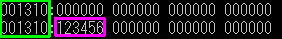
| here are the results... not R4 took the
PC of the calling address |
 |
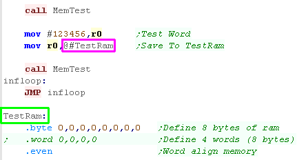
Not just Registers!
We've looked at registers and immediates - but of course PDP can
do far more!
Lets take a look at Writing to ram!
We can write to an address by using a label and putting a @ in front
of it. |
 |
The value was saved to Ram...
There's lots more of options for saving and loading... but we'll
leave them until next time! |
 |
 |
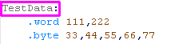
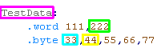
We can define BYTEs and WORDs in our code for
our reading or writing... but PDP-11 is 16 bit and needs to be
WORD aligned - we should put an .EVEN command after the data.
|
Lesson
2 - Addressing modes
We looked at the basics of PDP last time, but it's time to
start getting serious!
Although it's relatively old, PDP-11 has a
huge number of addressing modes... and now it's time to learn
about all of them. |
|
|
|
|
0R - Register
Register addressing is something we've already looked at... its
where we're transferring data between registers!
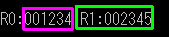
In this example, we transfer the value in R1
into R0
We just specify the register name R0-R5.... Note: R6 is called SP,
and R7 is PC |
 |
| We transferred R1 to R0 |
 |
Wondering what 0R and 1R Mean?
We'll these are the octal representation in the bytecode..R would
be a register number - and this code would be used in the source
or destination field to specify the
value source...
You don't actually need to know these for programming - but we'll
include them here for completeness |
|
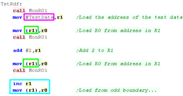
1R - Register Deferred
Register deferred sounds
confusing, but it doesn't need to be!... this would be called
'Indirect register addressing' on other systems....
Basically, we're going to read from an address - and that
address is held in a register... to do this
we put the register in bracket.
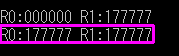
Notice that whether we read a word from an odd boundary or even
one, we get the same result!... this is
because the PDP-11 requires the word data to be aligned on even
boundaries.
Low bytes are stored at even numbered addresses, and High bytes
are stored at odd addresses So we get the same value as last
time,even though address is +1 |
 |
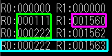
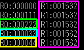
| The values are read in from the address in R1 into R0 |
 |
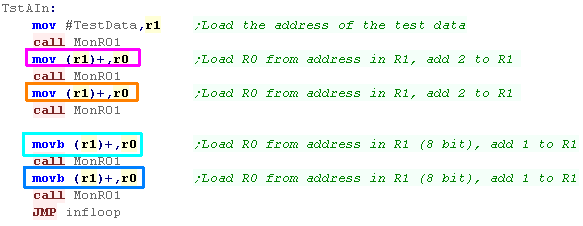
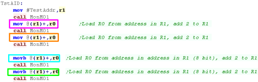
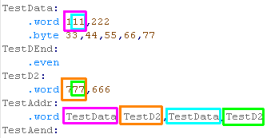
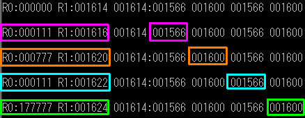
2R - Auto Increment
We read from a register's address last time... we can also get
that address to increment after each read...
We can use a Register as a source address - and sequentially read
from consecutive memory addresses (for example if we're processing
a bitmap file, or a text string)
We just put the register in brackets () and
and add a + to the end... this is because the value in the
register goes up AFTER the read
If we're reading in words, the address will increase by 2 - if
We're reading in bytes, the address will increase by 1
MOV (SP)+,Rn is effectively our POP command |
 |
| Here are the results |
 |
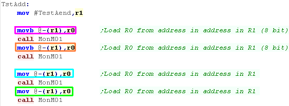
3R - Auto Increment Deferred
This is a combination of the
last two - we'll read from the address in the address in a
register - then increment the register by 2
Effectively the register should point to an entry in a vector
table (a table of address pointers)
We specify this addressing mode by using @(Rn)+
|
 |
Here are the results
|
 |
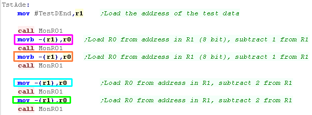
4R - Auto Decrement
This is the opposite of "2R - Auto Increment"
We specify -(Rn) ... note this time the
decrement occurs BEFORE the read
MOV Rn,-(SP) effectively our PUSH command |
 |
| Here are the results |
 |
5R - Auto Decrement Deferred
This is the reverse of 3R -
we'll decrement the address by 2, and then we'll read from the
address in the address in that register
This is useful for reading from a list of pointers backwards...
We specify @-(Rn) to use Auto Decrement
Deferred mode |
|
Here are the results
|
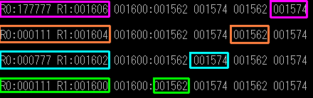 |
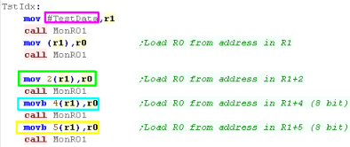
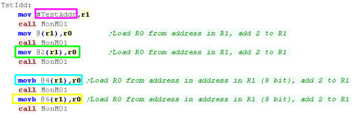
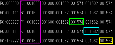
6R - Indexed
Indexed addressing takes the value from an address calculated
from a register PLUS an offset
This allows us to point a register to a bank of data (for a
player, or device driver for example), and give an offset for
read/write operations...
The format is v(Rn) - where v is a positive
or negative offset from the register.
|
 |
| We've read in the values from the addresses |
 |
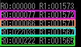
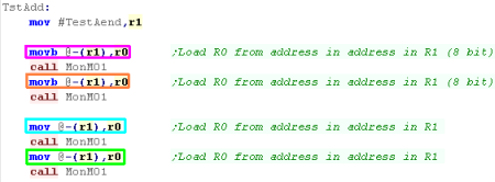
7R - Indexed Deferred
Indexed Deferred is a combination of the last two... the address
in a register plus an offset is used as a source address in a
vector table - and that address is used as the source address for
the final value.
To specify this we use @v(Rn) where v s |
 |
| Here are the results |
 |
|
If the
register parameter is the program counter (R7 - PC) we have 4
extra 'effective' options...
We don't have to worry about this - The assembler handles this
for us as needed.
|
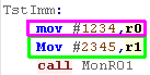
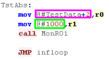
27 - Immediate
We've seen Immediate values many times, these are just values
specified in the line of the code...
They are specified with #number |
 |
| here are the results |
 |
37 - Absolute
Absolute addresses are where we're reading in from a fixed
memory location...
Normally we will probably use a label,
but we can also use a numeric address.
|
 |
Here are the results
|
 |
67 - Relative
Relative addressing is where
we are using a value read from memory relative to the Program
Counter (the current running code)
.
The program counter can be addressed with .
- this returns the current line of code. we can use this as part
of a relative calculation |
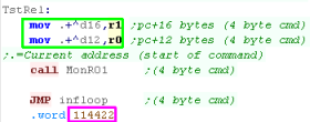 |
| Both calculations load from the same address |
 |
During Execution in the processor the PC register
always points to the next command (the next word after the current
command).
the full stop (.) is the assembler directive, which represents the
address of the current command, so is 2 bytes before the Program
Counter. |
|
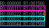
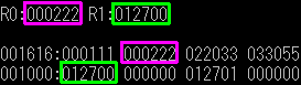
77 - Relative deferred
| Once again - Relative deferred uses an
offset from the program counter, but this time it loads the
address from the resulting address - and gets the value from that
address for the parameter |
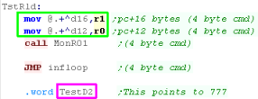 |
| The value at TestD2 (000777) was loaded
into both registers |
 |
Lesson
3 - Conditions, branches and loops
We've looked at loading in fixed values, but we need to have
some way of controlling what happens depending on the values in
registers and memory...
This is where conditions come in!... lets learn all about them.
|
|
|
|
|
Looping with SOB!
on some systems looping can be a son of a bitch... but when we
need to do a loop with PDP, there's no need to cry* - the PDP
makes it easy with SOB! (Subtract One and Branch)
This will subtract 1 from the specified register, then loop back
to the specified label if the register isn't zero - we can use
this as our loop (like Z80 DJNZ)
In this example we add 2 to R0 each loop
*Excuse me for the terrible jokes.. i'm done now!... probably... |
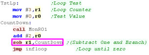 |
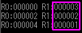
| The loop ran 3 times based on the count
in R1 - because it stops when it reaches zero, there was no 4th
iteration |
 |
Fun with Flags.
As Branches are usually based on conditions, Before we look at
them, lets learn how to set and clear the flags - there are
special commands to do this!
Each flag has a 'set' command and a 'clear' command - we'll learn
what each flag means and how to use it in a moment.
Action
|
N |
Z |
V |
C |
All |
| Set |
SEN
|
SEZ
|
SEV
|
SEC
|
SCC
|
| Clear |
CLN |
CLZ |
CLV |
CLC |
CCC |
We're using a function called 'MonFlg' to show the flags, but it's
function is outside the scope of today's lesson
|
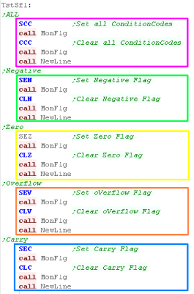 |
The flags will be set accordingly
|
 |
We can back up and restore the flags in one of our registers
with MFPS and MTPS
MFPS will back up the flags to a register
MTPS will restore the flags from the
register
It should be noted that these commands do not exist on many
earlier PDP-11 versions. |
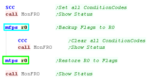 |
| We backed up the flags into R0 ... zeroed
them and restored them from R0 |
 |
You may think
that's a lot of 'set' and 'clear' commands - but that's just the
half of it!
You can actually 'create' commands with the correct combination
of bits to set or clear any combination of flags in one go! -
you'll need to see the byte data the command compiles to to
figure it out though - and it's probably not that useful!
|
 |
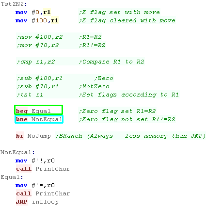
Zero flag (Z)... Equal / Not Equal
Whenever we do a MOVe, CoMPare, ADD or SUB the flags will be
set.
If the result is ZERO - Z will be true - otherwise it will be
false... Like many systems CMP sets the flags like a subtract
command, but doesn't change the registers.... so if the difference
is zero
BEQ will branch if Z is set (Branch if EQual
BNE will branch if Z is not set (Branch if
Not Equal)
There is a special branch... BR - this will ALWAYS branch!
Also notice the TST command - this will
update the flags according to a register - but does not change the
register itself. |
 |
| The sample will show = if the result is Zero... or !=
if the result is not zero |
 |
| BRanch and JMP
do the same thing in the sense that they always jump... but
BRanch takes fewer bytes - BR uses an offset in the 2 byte
command, whereas JMP uses an absolute address (total of 4
bytes)... but BRanch cannot 'jump' far away from the current
label (approx -256 to +255 bytes away) |
|
|
You'll notice lots of remmed out code -
this is other tests you can do to see how the flags are affected
- you really need to download the code and try it yourself,or
just watch the video!
|
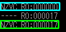
Unsigned - Carry (C), Negative (N)
and oVerflow (V)
Because of the way the CMP command works like a subtraction,
with unsigned numbers the Carry flag will be set
Signed numbers are a little more tricky, we'll have to consider
the oVerflow and Negative commands - fortunately the CPU handles
this for us, and gives us 4 commands for each
| Condition |
Signed |
Unsigned |
<
|
BLT
|
BLO
|
<=
|
BLE
|
BLOS
|
>=
|
BGE
|
BHIS
|
>
|
BGT
|
BHI
|
|
 |
The flags will be shown, and a < or > will be displayed
onscreen
|
 |
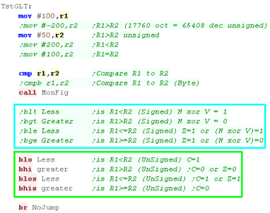
oVerflow (V) - those pesky signs!
Because when considering a signed number 32767 is 32767, but
32768 is -1... we have to be careful that adding a number, or
subtracting one won't cause the sign flag to unexpectedly
change... this is what the overflow flag (V) is for!
BVS will branch if overflow is set
BVC will branch if overflow is clear |
 |
| O will be shown on Overflow... NO will be shown if there's No
Overflow |
 |
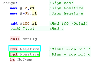
Negative (N) - Sign bit
The N flag will allow us to check a sign - it effectively takes
the value of the top bit of the result of the last operation.
BMI will branch if the value is negative
(minus - N set)
BPL will branch if the value is positive
(plus - N clear) |
 |
| The flags and a + or - will be shown |
 |
Carry flag (C)
When an addition or subtraction goes over the limit of a
register, or a bit shifting operation pushes a bit out the
register the Carry flag is set (it acts as a borrow with
subtraction)
BCS will Branch if Carry is Set
BCC will Branch if Carry is Clear |
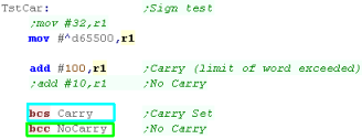 |
| C will be shown if the Carry is set ... - will be shown if it
isn't |
 |
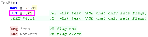
If we want to test one or more bits in a register we can do so
with the BIT command!
This is effectively an AND command - but it does not change the
registers - it will set the Zero flag depending on if the bits are
zero or not. |
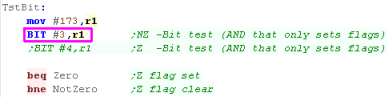 |
| Z or NZ will be shown to the screen. |
 |
Lesson
4 - Stack and More Maths
We looked at the AutoINC and AutoDEC addressing modes before
that effectively work as PUSH and POP - but we didn't explain
those!... lets look now at the stack and how JSR/CALL works
We'll also have a look at Multiplication and Division... and
using the Carry to combine two registers for 32 bit maths!
|
|
|
|
|
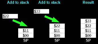
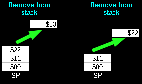
Stack Attack!
'Stacks' in assembly are like an
'In tray' for temporary storage...
Imagine we have an In-Tray... we can put items in it, but only
ever take the top item off... we can store lots of paper - but
have to take it off in the same order we put it on!... this is
what a stack does!
If we want to temporarily store a register - we can put it's value
on the top of the stack... but we have to take them off in the
same order...
The stack will appear in memory, and the stack pointer goes DOWN
with each push on the stack... so if it starts at $01FF and we
push 1 byte, it will point to $01FE
(This screenshot is from the 6502 - but the principle is the same
for the PDP-11) |
|
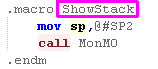
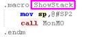
Macro-11 has MACROS!
In todays example we're going to define a MACRO!
This will create a 'command' that contains a series of other
commands - the assembler will replace any instance of 'ShowStack'
with the commands in the macro... |
 |
|
This is just a simple example - Macro-11 also
supports parameters: .MACRO testmac param1,param2 would define
two parameters for the macro... these can then be used within
the macro.
For full info see the Macro-11 documentation
|
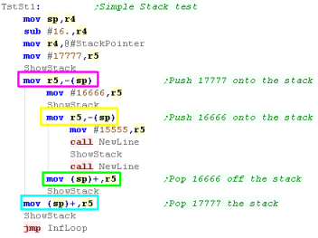
Using the Stack for
temporary storage
There will be many times we need to back up a register
temporarily and restore it later - the stack is great for this
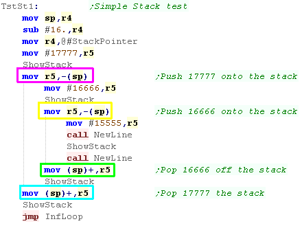
We can use MOV Rn,-(SP) to move values onto
the stack... we do it twice with R5 in
this example.
We can then restore it later with MOV (SP)+,Rn...
we also do this twice with R5 |
 |
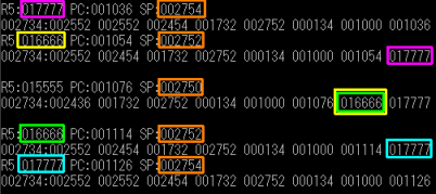
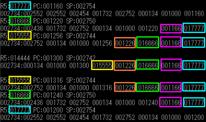
First We pushed 017777 onto the stack
via R5
Next We pushed 016666 onto the stack via
R5
Then we loaded R5 with with 015555
We then restored R5 popping it off the
stack - getting back 16666
We then restored R5 popping it off the stack
- getting back 17777
Notice how SP changes as values
are pushed and popped... SP always points to the Last item pushed
onto the stack |
 |
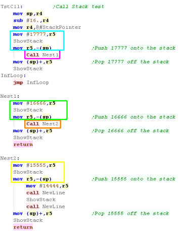
JSR/CALL and the stack
JSR will push a register onto the stack, and move the program
counter into that register...
The CALL command is the same as JSR PC - and is the simplest way
to call a subroutine - whenever we do this the return address will
be pushed onto the stack
in this example we'll push an item onto the stack...
call a sub... push an
item... call a sub and push
a final item,
We'll then pop all the items off the stack and return - in the
reverse order |
 |
| The Three Pushes (1,2,3) can be seen on the stack... with the two
Return addresses (1,2)
in between |
 |
Because the stack is used by the returning address,
we'll probably want to make sure the stack is in the same position
at the end of the subroutine as it was at the start... so POP off
what you PUSHED on!
If you're super clever you may want to do something tricky with
the stack and calls - but for starters keeping the stack the same
at the end as the start of a sub is best. |
|
Add and Subtract in
32 bits with ADC and SBC
Just like many other CPU's addition and subtraction that exceeds
the limit of a single register (16 bit on the PDP-11) will affect
the carry flag
When Adding... the carry is effectively any bit that 'overflowed
when the value went over 65536
When Subtracting... the carry is effectively a Borrow, and will be
1 if the calculation went below zero.
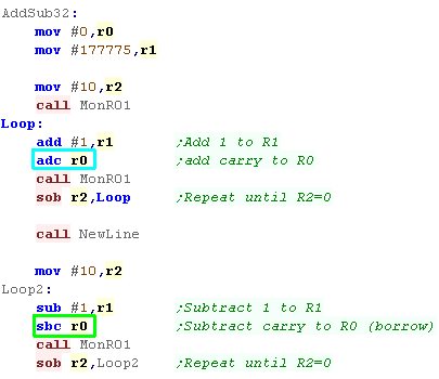
To perform 32bit+ addition, first we do the ADD command as normal
for the low word... then we do ADC for the high word
To perform 32bit+ subtraction, first we do the SUB command as
normal for the low word... then we do SBC for the high word |
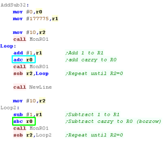 |
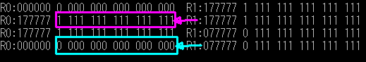
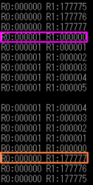
The first example is the ADD/ADC one - when the bottom word (R1)
overflows - ADC adds one to R0
The first example is the SUB/SBC one - when the bottom word (R1)
goes below zero - SBC subtracts0
one from R0
|
|
Multiplication and
Division
When we perform a MULtiply command - we can perform an 16 or 32
bit multiplication, this is decided by the number of the
destination register...
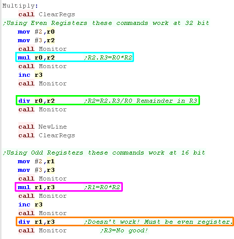
If an EVEN numbered register is used with MUL
(like R2) the result will be stored in 32 bit pair (R2,R3)
if an ODD numbered register is used with MUL
(Like R3) the result will be stored as a single 16 bit register
(R3)
DIVide can only work with even registers...
using destination R2 will mean the divided value is in 32 bit pair
(R2,R3) - the integer result will be stored in R2 - the remainder
will be in R3
Using DIVide with an odd pair will not
work (R3 is no good) |
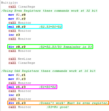 |
in Example 1 We MULtiplied R0 by R2 and
stored the result in 32bit pair R2,R3
in Example 2 we DIVided 32bit pair
R2,R3 by R0... R2 stored the whole number result... R3 stored the
remained
In Example 3 we MULtiplied R1 by R3, and
stored the result in 16bit register R3
Example 4 did not work - we tried
to use odd register R3 with DIV - this does not work.
|
 |
Lesson
5 - Logical and Bit operations
We've looked at some mathematical operations, but we've
really overlooked a lot so far... but we'll catch up now!
Lets take a look at the remaining major commands we'll need!
|
|
|
|
|
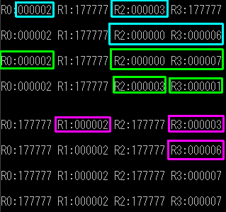
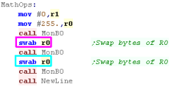
Swap Bytes with SWAB
All our registers are 16 bit - but we can swap the two bytes
within a register with the SWAB command
Here we'll swap the two bytes of R0 with SWAB
then swap them back |
 |
| The top and bottom nibbles were swapped -
then swapped back again! |
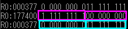 |
Sign Extending a 16
bit value to 32 bit with SXT
If we want to extend a 16 bit register to a 32 bit register pair
we can do so with SXT...
effectively this command fills a register with the sign bit - so
in this example we update the flags with TST |
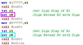 |
In the first example SXT extended the 1
sign bit, filling R0 with ones
In the second example SXT extended the 0
bit, filling R0 with zeros |
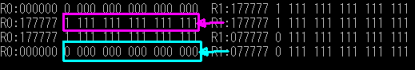 |
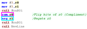
Flipping bits with
COM - Positive to negative with NEG
If we want to flip all the bits in a register, we can do this
with COMpliment...
We may want to convert a positive to negative (or visa versa) we
can do this with NEGate... this effectively
flips all the bits, and adds one |
 |
COM flipped all the bits...
NEG flipped all the bits and added 1 (effectively sign
flipping the value) |
 |
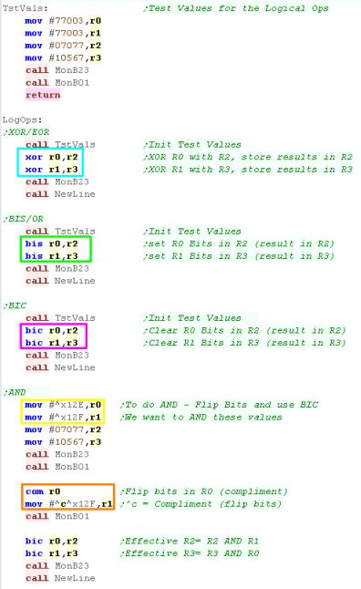
Logical Ops... XOR,
BIS ,BIC
PDP-11 Logical OPS are slightly different
XOR (eXclusive OR) will flip the bits in the
destination when the parameters bits are 1... this is known as EOR
on some CPUS
BIS (BIt Set) will set (1) the bits in the
destination when the parameters bits are 1... this is known as OR
on other CPUs
BIC (BIt Clear) will clear (0) the
bits in the destination when the parameters bits are 1... this is
the opposite of AND on other CPUS
| Operation |
XOR |
BIS |
BIC |
| Destination Reg |
10101010 |
10101010 |
10101010 |
| Parameter Reg |
11110000 |
11110000 |
11110000 |
| Result |
01011010
|
11111010
|
00001010
|
if we want to do an AND we'll
have to be tricky... We need to flip the bits of the value
we want to AND and do a BIC - this will have the same
effect... we can flip the bits with a COM
command... or by getting the assembler to calculate a compliment
with the ^C prefix to a value
|
 |
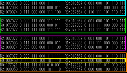
| The results of the XOR, BIS,
BIC and fake AND
command can be seen here |
|
|
^C tells the
assembler to calculate the logical compliment (bit flipped)
value... we can chain this with other statements, so ^C^D3 would
complement decimal value 3... ^C^D0F
would compliment Hex value 0F
|
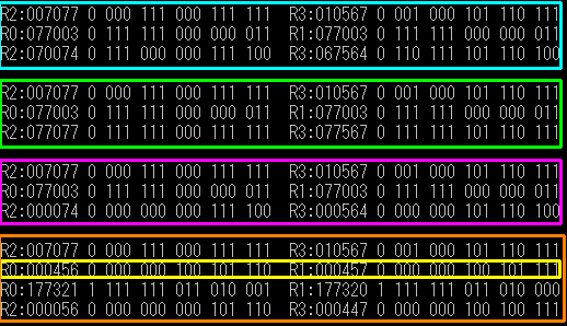
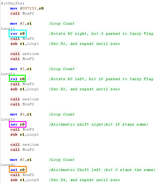
Bit Shifts ROR, ROL,
ASR, ASL
Like most systems, PDP-11 has a range of shifting and rotating
operations
ROR - ROtate Right using carry
ROL - ROtate Left using carry
ASR - Arithmatic Shift Right
ASL - Arithmatic Shift Left
We'll test each command with a loop. |
 |
The result of each command can be seen here.
ROR - Bit 0 will be moved to the carry - the
old carry moves to bit 15
ROL - Bit 15 will be moved to the carry -
the old carry moves to bit 0
ASR - Arithmatic Shift Right - new Bit 15
will be the same as last bit 15
ASL - Arithmatic Shift Left - new
Bit 0 will be zero |
 |
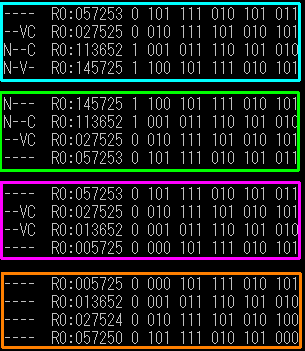
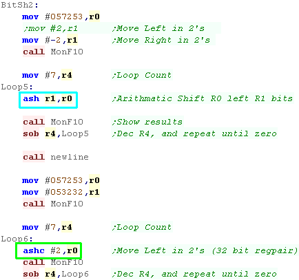
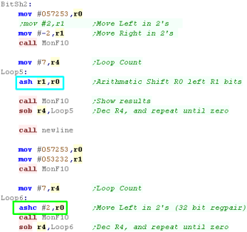
Bit Shifts ASH n
bits... ASHC for 32 bit shifts
If we want to move by more than one bit we can use ASH
A positive shift will shift Left
A negative shift will shift Right
ASH will shift a single register... ASHC will
use a pair of registers (eg R0,R1) as a 32 bit pair |
 |
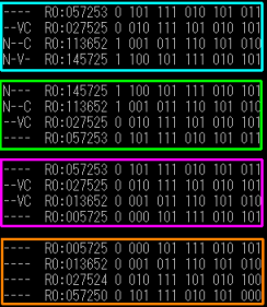
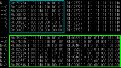
| Here are the results... ASH only affects
one register... ASHC affects the pair of
registers |
 |