

Simple Samples
In this series we'll look at some simple self contained examples.


Our example
| We're going to create an example which draws a 4 color 8x8 smiley. The drawing routine will be on the Main Cpu (using MAIN CPU RAM for VRAM)... but we need the SUB CPU to read the keys, we also need it to set up the screen memory layout. |
 |
| The UKNC has two CPUs!... The main one runs our
program, and the SUB CPU handles peripherals! We need the Sub CPU to do the keyboard, and it also typically handles graphics, but we can remap the sub CPU's Scan Line table, so that 2 bitplanes are accessible via standard ram! |
 |
Sending
commands to the SUB CPU (PP)
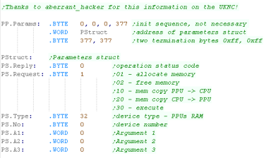
| We need to transfer data to the SUB CPU, and tell it to act. It's ROM will take the command, transfer the program to it's memory and run it... in this case our sprite. We need a parameter command (PP.Params) - which includes a pointer to a 10 byte structure (PStruct) We'll tweak the parts of PS depending on what we need the SUB CPU to do. |
 |
| We also have a 'Flag'... this is not part of the PP command, but we get the Sub CPU to alter it (Via the RAP) to tell the Main CPU the Sub CPU is done. |  |
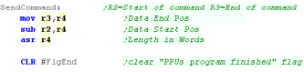
| Our SendCommand function takes
a command start and end address in R2/R3 We clear the flag that will be used when the program ends. |
 |
| First we use command 1 to get the SUB CPU to allocate memory | 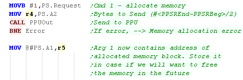 |
| We now need to transfer our program from the MAIN CPU to the SUB CPU... we use Command 20 to do this. | 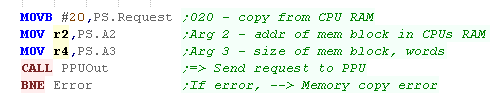 |
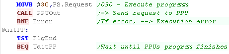
| Now we tell the SUB CPU to execute the
program with Command 30 We wait for the program to set the End flag - showing it's complete |
 |
| Once the program has finished we free the memory on the SUB Cpu with command 02 | 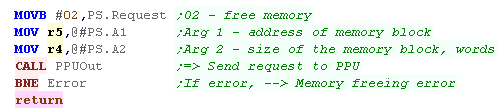 |
| PPUOUT transfers each PPU command to the SUB CPU | 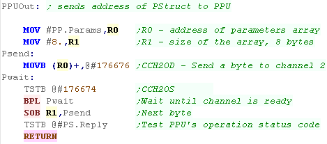 |
| We need to get the
SUB CPU (PP) to do the work of configuring the Scan Line TABle
which defines the screen |
 |
UKNC SLTAB entries
*** Thanks to aberrant_hacker for this
information on the UKNC!... he's working on a port of ChibiAkumas to the
UKNC... check it out here!
***
The STAB is the line definition table, it
starts at address 270, each line has two words, the first is the VRAM
address of that line, the second is a pointer to the next line, and a few
options... more options can be configured using a 4 word SLTAB definition.
There are 3 types of record, one uses 2 words
per record, the other two use 4 words... what record is next is defined by
the L and S bits of the previous line.
312 (1..312) lines is SECAM half-frame
309 (1..309) SLTAB records in total (lines 4..312 of SECAM's half-frame)
scanlines 1..19 are not visible due to the vertical blanking interval
scanlines 20..307 are visible (lines 23-310 of SECAM's half-frame)
scanlines 308..309 are not visible due to the vertical blanking interval
309 (1..309) SLTAB records in total (lines 4..312 of SECAM's half-frame)
scanlines 1..19 are not visible due to the vertical blanking interval
scanlines 20..307 are visible (lines 23-310 of SECAM's half-frame)
scanlines 308..309 are not visible due to the vertical blanking interval
| F | E | D | C | B | A | 9 | 8 | 7 | 6 | 5 | 4 | 3 | 2 | 1 | 0 | ||
|
2 word record |
V | V | V | V | V | V | V | V | V | V | V | V | V | V | V | V | V=Vram Address |
| A | A | A | A | A | A | A | A | A | A | A | A | A | S | L | C |
C=Toggle Cursor on/off L=Length
of next record (2/4 words) S= 4-word selector (Options/Palette) / 2-word address bit 2 A=Address bits 3-15 |
| F | E | D | C | B | A | 9 | 8 | 7 | 6 | 5 | 4 | 3 | 2 | 1 | 0 | ||
| 4 word record Options |
- | C | C | C | C | C | C | C | G | G | G | T | Y | R | G | B | YRGB=Cursor color & Brightness / T=Type (Char/Graphic) / G=Graphic Cursor pos / C=Cursor pos |
| - | - | - | - | - | - | - | - | - | - | S | S | - | R | G | B | RGB= Line Brightness S=Scale (640/320/160/80) | |
| V | V | V | V | V | V | V | V | V | V | V | V | V | V | V | V | V=Vram Address | |
| A | A | A | A | A | A | A | A | A | A | A | A | A | S | L | C |
C=Toggle Cursor on/off L=Length
of next record (2/4 words) S= 4-word selector (Options/Palette) / 2-word address bit 2 A=Address bits 3-15 |
| F | E | D | C | B | A | 9 | 8 | 7 | 6 | 5 | 4 | 3 | 2 | 1 | 0 | ||
| 4 word record palette |
Y | R | G | B | Y | R | G | B | Y | R | G | B | Y | R | G | B | Palette bit combos %011 %010 %001 %001 |
| Y | R | G | B | Y | R | G | B | Y | R | G | B | Y | R | G | B | Palette bit combos %111 %110 %101 %100 | |
| V | V | V | V | V | V | V | V | V | V | V | V | V | V | V | V | V=Vram Address | |
| A | A | A | A | A | A | A | A | A | A | A | A | A | S | L | C |
C=Toggle Cursor on/off L=Length
of next record (2/4 words) S= 4-word selector (Options/Palette) / 2-word address bit 2 A=Address bits 3-15 |
Functions for defining the SLTAB
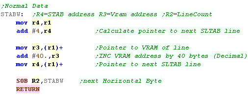
| We're going to create some functions which will define the 4 kinds
of line we'll use. The first is a normal 2 word line. This defines the VRAM address of the line in the first word, and a pointer to the next line, with settings of the line, in the second word. |
 |
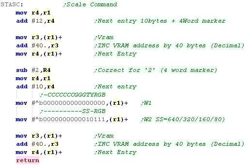
The second is a 'Scale command' (Options)... Here we're setting the Scale to 320 pixels... This command defines 2 lines, the first is a 'normal' 2 word line, but this defines the form of the second line... we tell the system the next line will have 4 words, and be an 'Options' line This is done by bits 4/5 of the second word. |
 |
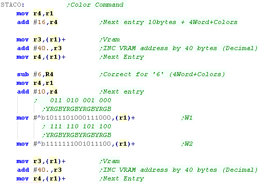
| The third sets the colors (palette) This command defines 2 lines, the first is a 'normal' 2 word line, but this defines the form of the second line... we tell the system the next line will have 4 words, and be an 'colors' line Each cluster of 4 bits defines a color, in the format YRGB - where Y is brightness. We're remapping 'Blue' (bit pattern %001) to a dark cyan. (Bit pattern %0011) |
 |
| The fourth is a 'filler' line... this just shows as single VRAM line, and can be used for 'invisible area' | 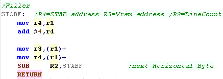 |
Defining our SLTAB
| We're going to need to get the SUB CPU (PP) to do our work, We send and execute this with the code we wrote last time! |
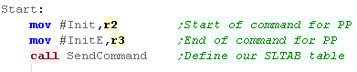 |
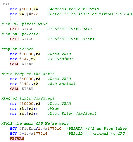
| We're going to actually define our table! The definition of our table will be at address 4000 in octal (in PP RAM)... we need to attach this to the start of the firmware SLTAB which appears at 270 (Vram address) and 272 (Pointer to next record) The first four lines we define set the scale and color. The next 32 are the top 'unused' area of the screen. Then we define 240 actual screen lines - we define these from 40000+... Note: This is within the CPU addressable ram area - so we won't need the RAP device! Finally we create a final entry that points to itself - this is the end of the screen. |
 |
The Keyboard
hardware
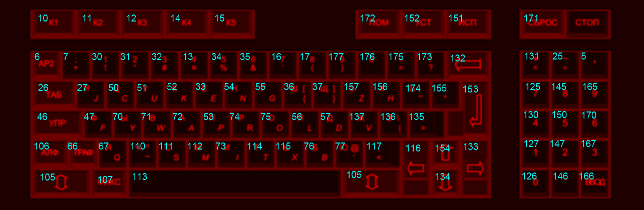
| Each key on the UKNC keyboard has a 'keycode' which uniquely
identifies it. This is passed in entirely when a key is pressed down, or partially when a key is released. |
 |
|||||||||||||||||||||||||||
| We can read the keyboard only from the PPU, The best way is by
writing our own Keyboard interrupt handler, and copying it's address
to memory address #300 in octal... This will cause it to execute
each time a key is pressed or released. We can then read port 177702 to get the details of the key that was pressed. Bit 7 will be zero if a key was pressed down... Bits 0-6 will give the full keycode of the key pressed down. Bit 7 will be 1 if a key was released up... Bits 0-3 will give the partial keycode of the key released - this means it is not possible to 100% uniquely identify the key that was released. |
|
Reading from
the keyboard
| We're going to set up a
keyboard handler on the SUB CPU, however it will write its results
to the main CPU's ram via the RAP device - allowing us to use it's
results easily! We'll transfer two bytes - the first is the raw data from the keyboard (For testing), and a 1 byte representation of the directions, and possible fire buttons (for our games) |
 |
| We'll transfer the program to the SUB CPU in the same way as
before, The first program will just have one task... Set up
the interrupt! To do this, we just need to put the address of our interrupt handler in address 300 (in octal) of the memory of the SUB CPU (peripheral cpu - not main CPU memory!) |
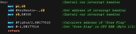 |
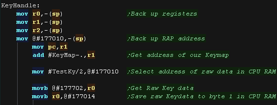
| We're using the RAP device to write to MAIN CPU RAM from the SUB
CPU The main cpu uses 2 banks for alternating bytes, so we halve the destination address, and write this to port 177010 We then read in the data from the keyboard hardware from port 177702 We send this raw data via the RAP device to the first byte with port 177014 |
 |
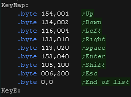
| We're going to process this data, and convert it into a simulated
'Joystick' We'll return a single byte, where each direction will be a bit in the format %P321RLDU - with keys Up Down Left Right, Space Enter and Shift for fire, and Escape for a pause button. We use a Keymap to do this, which uses pairs of bytes, the first is the Keycode, the second is the bitmask. |
 |
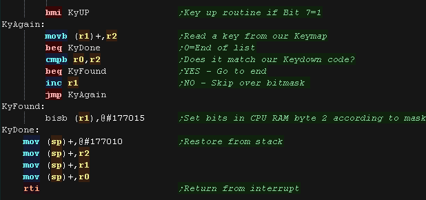
| if bit 7 of our read in byte is a zero, a key has been pressed
down. We scan through the KeyMap until we find a match (or we get to the zero at the end of the list) If we find a match We set the bit from the second byte with BIS We set the second byte via the RAP device with port 177015 |
 |
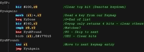
| if bit 7 is one then a key is released. Once again we scan the keymap, BUT only 4 bits of the keycode are returned when a key is released, so we use 'bic #360,r2' to ignore the other 3 bits of the tested keycode. For any matches, We clear the bits with BIC, because there are only 4 bits returned by the hardware, multiple keys could match. |
 |
| Space and Enter
aren't really the best fire buttons as there's some 'keyclash'
with the other keys! Still it's only a test, and you can easily choose your own keys just by changing the 'Keymap' to something better. |
 |
Our Sprite drawing routine
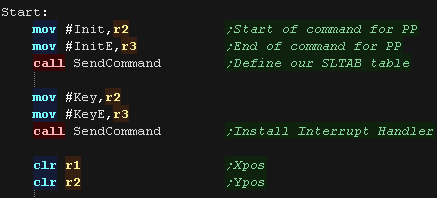
| At the start of our program we need to set up the screen by
running the INIT command on the sub cpu. then we need to install the keyboard interrupt handler with the KEY command. we use R1,R2 as our X,Y pos for our smiley |
 |
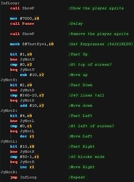
| The main loop of our program will show the sprite to the screen,
pause a moment, then remove it (by showing it a second time) We then read in from TestKy - which is set by the interrupt handler. We test each direction bit in the Testky byte. If a direction is pressed, we check if we're already at the edge of the screen, if not we move in that direction. We repeat for each direction. We then loop, running the whole procedure again. |
 |
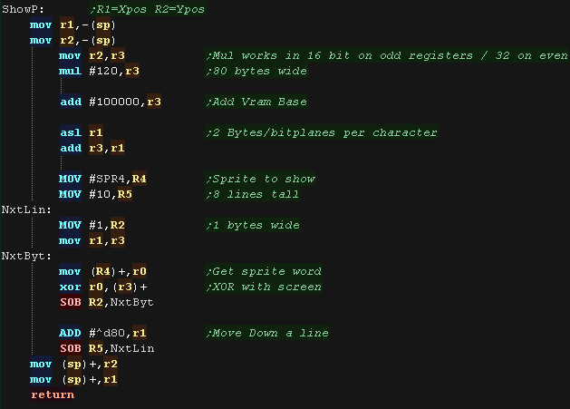
| Our Showsprite routine will show our smiley at X,Y position R1,R2 We use XOR, meaning the sprite is inverted with the screen ram... this means if we draw it twice to the screen the second time will remove it. The VRAM base is 100000 in octal, each line is 320 pixels wide (40 chars) and there are 2 one byte bitplanes... so to calculate a VRAM destination the formula is: In decimal: VRAM = 32768 + (80 * Ypos) + (2 * Xpos) In octal: VRAM = 100000 + (120 * Ypos) + (2 * Xpos) |
 |

Our Example
| Our example allows us to type in the octal value for a register,
it hen shows it back as text! This is intended to help you write your own test programs, or try out the effect of various commands on registers! |
 |
Showing a
register
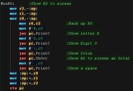
| The 'MonR0' function will monitor the R0 register, showing its
contents to the screen, using 'PrintC' to show characters. First we show a text label to the screen. We need to backup R0 while we do this, so we move it into R2. Now we show the characters 'R0:' to the screen, then run the 'ShOct' function to show the R0 register's contents to the screen. All registers are backed up and restored via the stack, so they are unchanged upon return. |
 |
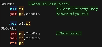
| The 'ShOct' subroutine will show all the digits of our octal
number. The maximum value for a 16 bit value in octal is 177777 . This means we need to show one 1 bit number, followed by five 3 bit digits. |
 |
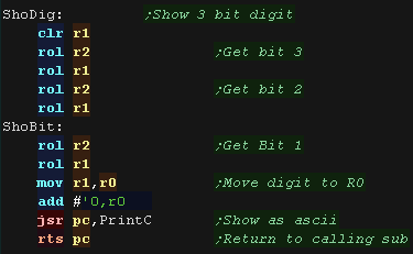
| Our show digit and show bit routines shift 1 or 3 bits from our
source (R0 has previously been moved to R2). We move the bits into R1 and add the character '0' to covert it to ASCII. We then print the character to the screen with 'PrintC'. |
 |
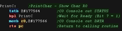
| The actual print character routine first checks 177564 (in octal)
to see if the console is ready to receive data. If the top bit of the byte is 0 then the port is currently busy. We test this with BPL (Branch if PLus). When the console is ready, we send the character to port 177566 (in octal). |
 |
Reading an octal value
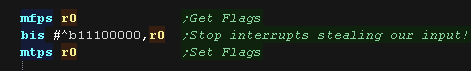
| First we need to disable interrupts. This is because otherwise the RT-11 operating system will steal our key presses! We do this by setting bits 5-7 of the flags, setting the priority to 7. |
 |
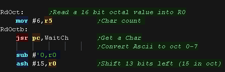
| The 'RdOct' function will read in 6 characters into register R0. We call subroutine 'WaitCh' to read in a character and convert it to a number by subtracting ASCII '0'. We then shift the 3 bits we want to the far left of the word (shifting 13 bits left / #15 in octal). |
 |
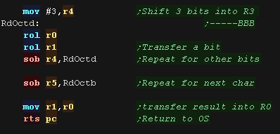
| Next we shift the 3 bits we want into our temporary destination
register R1, we repeat for the other characters, then move R1 into
R0. |
 |
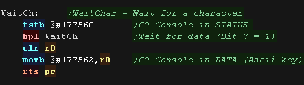
| The actual wait character routine first checks 177560 (in octal)
to see if the console has any data to send. If the top bit of the byte is 0 there's nothing waiting. We test this with BPL (Branch if PLus). When there is data waiting, we read the character from port 177562 (in octal). |
 |
| View Options |
| Default Dark |
| Simple (Hide this menu) |
| Print Mode (white background) |
| Top Menu |
| ***Main Menu*** |
| Youtube channel |
| Patreon |
| Introduction to Assembly (Basics for absolute beginners) |
| Amazon Affiliate Link |
| AkuSprite Editor |
| ChibiTracker |
| Dec/Bin/Hex/Oct/Ascii Table |
| Alt Tech |
| Archive.org |
| Bitchute |
| Odysee |
| Rumble |
| DailyMotion |
| Please note: I wlll upload more content to these alt platforms based on the views they bring in |
| 68000 Content |
| ***68000 Tutorial List*** |
Learn 68000 Assembly  |
| Hello World Series |
| Platform Specific Series |
| Simple Samples |
| Grime 68000 |
| 68000 Downloads |
| 68000 Cheatsheet |
| Sources.7z |
| DevTools kit |
| 68000 Platforms |
| Amiga 500 |
| Atari ST |
| Neo Geo |
| Sega Genesis / Mega Drive |
| Sinclair QL |
| X68000 (Sharp x68k) |
| 8086 Content |
| Learn 8086 Assembly |
| Platform Specific Series |
| Hello World Series |
| Simple Samples |
| 8086 Downloads |
| 8086 Cheatsheet |
| Sources.7z |
| DevTools kit |
| 8086 Platforms |
| Wonderswan |
| MsDos |
| ARM Content |
| Learn ARM Assembly |
| Learn ARM Thumb Assembly |
| Platform Specific Series |
| Hello World |
| Simple Samples |
| ARM Downloads |
| ARM Cheatsheet |
| Sources.7z |
| DevTools kit |
| ARM Platforms |
| Gameboy Advance |
| Nintendo DS |
| Risc Os |
| Risc-V Content |
| Learn Risc-V Assembly |
| Risc-V Downloads |
| Risc-V Cheatsheet |
| Sources.7z |
| DevTools kit |
| MIPS Content |
| Learn Risc-V Assembly |
| Platform Specific Series |
| Hello World |
| Simple Samples |
| MIPS Downloads |
| MIPS Cheatsheet |
| Sources.7z |
| DevTools kit |
| MIPS Platforms |
| Playstation |
| N64 |
| PDP-11 Content |
| Learn PDP-11 Assembly |
| Platform Specific Series |
| Simple Samples |
| PDP-11 Downloads |
| PDP-11 Cheatsheet |
| Sources.7z |
| DevTools kit |
| PDP-11 Platforms |
| PDP-11 |
| UKNC |
| TMS9900 Content |
| Learn TMS9900 Assembly |
| Platform Specific Series |
| Hello World |
| TMS9900 Downloads |
| TMS9900 Cheatsheet |
| Sources.7z |
| DevTools kit |
| TMS9900 Platforms |
| Ti 99 |
| 6809 Content |
| Learn 6809 Assembly |
| Learn 6309 Assembly |
| Platform Specific Series |
| Hello World Series |
| Simple Samples |
| 6809 Downloads |
| 6809/6309 Cheatsheet |
| Sources.7z |
| DevTools kit |
| 6809 Platforms |
| Dragon 32/Tandy Coco |
| Fujitsu FM7 |
| TRS-80 Coco 3 |
| Vectrex |
| 65816 Content |
| Learn 65816 Assembly |
| Hello World |
| Simple Samples |
| 65816 Downloads |
| 65816 Cheatsheet |
| Sources.7z |
| DevTools kit |
| 65816 Platforms |
| SNES |
| eZ80 Content |
| Learn eZ80 Assembly |
| Platform Specific Series |
| eZ80 Downloads |
| eZ80 Cheatsheet |
| Sources.7z |
| DevTools kit |
| eZ80 Platforms |
| Ti84 PCE |
| IBM370 Content |
| Learn IBM370 Assembly |
| Simple Samples |
| IBM370 Downloads |
| IBM370 Cheatsheet |
| Sources.7z |
| DevTools kit |
| Super-H Content |
| Learn SH2 Assembly |
| Hello World Series |
| Simple Samples |
| SH2 Downloads |
| SH2 Cheatsheet |
| Sources.7z |
| DevTools kit |
| SH2 Platforms |
| 32x |
| Saturn |
| PowerPC Content |
| Learn PowerPC Assembly |
| Hello World Series |
| Simple Samples |
| PowerPC Downloads |
| PowerPC Cheatsheet |
| Sources.7z |
| DevTools kit |
| PowerPC Platforms |
| Gamecube |
| Work in Progress |
| ChibiAndroids |
| Misc bits |
| Ruby programming |
Buy my Assembly programming book
on Amazon in Print or Kindle!


Available worldwide!
Search 'ChibiAkumas' on
your local Amazon website!
Click here for more info!


Buy my Assembly programming book
on Amazon in Print or Kindle!
Available worldwide!
Search 'ChibiAkumas' on
your local Amazon website!
Click here for more info!
Buy my Assembly programming book
on Amazon in Print or Kindle!
Available worldwide!
Search 'ChibiAkumas' on
your local Amazon website!
Click here for more info!
Buy my Assembly programming book
on Amazon in Print or Kindle!
Available worldwide!
Search 'ChibiAkumas' on
your local Amazon website!
Click here for more info!
Buy my Assembly programming book
on Amazon in Print or Kindle!
Available worldwide!
Search 'ChibiAkumas' on
your local Amazon website!
Click here for more info!
Buy my Assembly programming book
on Amazon in Print or Kindle!
Available worldwide!
Search 'ChibiAkumas' on
your local Amazon website!
Click here for more info!
Buy my Assembly programming book
on Amazon in Print or Kindle!
Available worldwide!
Search 'ChibiAkumas' on
your local Amazon website!
Click here for more info!
Buy my Assembly programming book
on Amazon in Print or Kindle!
Available worldwide!
Search 'ChibiAkumas' on
your local Amazon website!
Click here for more info!
Buy my Assembly programming book
on Amazon in Print or Kindle!
Available worldwide!
Search 'ChibiAkumas' on
your local Amazon website!
Click here for more info!
Buy my Assembly programming book
on Amazon in Print or Kindle!
Available worldwide!
Search 'ChibiAkumas' on
your local Amazon website!
Click here for more info!
Buy my Assembly programming book
on Amazon in Print or Kindle!
Available worldwide!
Search 'ChibiAkumas' on
your local Amazon website!
Click here for more info!