You should know Z80 already, If you don't please go through the Basic Z80 Assembly Lessons first!
| Function | Purpose | Registers unchanged |
| CLS | Clear the screen. | All may have changed |
| Locate | Move the text cursor to a new (X,Y) location where H=X and L=0 and the top left corner of the screen is (0,0) | BC,HL,DE unchanged |
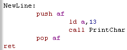
| NewLine | Move the cursor to the start of the next screen line | BC,HL,DE unchanged |
| PrintChar | Print the character in A to the screen | BC,HL,DE unchanged |
| WaitChar | Wait for a keypress, and store it's character in A when we get it | BC,HL,DE unchanged |
| PrintString | Print a string of characters from address HL ... string is CHR(255) terminated | BC and DE unchanged... HL now at end of string |
This will give us enough to test our ASM programs, and give us a foundation to build future lesson upon... later we can create better own routines that work the same but don't need the firmware... but that's more complex and will be too much for now!
Lets make a start! we'll go through each system, and look at how we can make the commands work
 |
Basic Text Functions on the Amstrad CPC: |
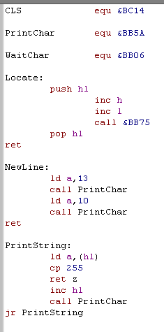
| The CPC version is pretty straight
forward! We use firmware call &BC14 to clear the screen (CLS). PrintChar is done by a firmware call to &BB5A WaitChar is done by firmware call &BB06 too... When it comes to Locate - we have a firmware call, but it considers the top left to be (1,1) so we have to INC H and L by 1 to make it work the same as on all systems. NewLine on the CPC is performed with Chr(13) (carriage return) and chr(10) (NewLine) - we just get the PrintChar call to do the work for us! PrintString is also straight forward, using the PrintChar command to print each character to screen. And that's it! |
 |
| As with the Basic
Series... the CPC is kind of the Benchmark for this development
series... and will continue to be unless someone builds a better
Z80 emulator with built in Assembler! The CPC is fairly kind to us too.. making these simple jobs... well... simple! |
 |
 |
Basic Text Functions on the ZX Spectrum: |
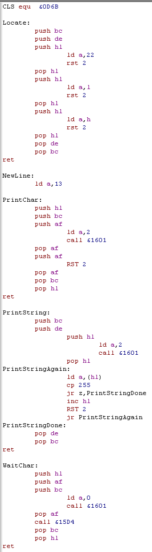
| The ZX spectrum is a little more
tricky! Firstly it corrupts all the registers, so we need to use PUSH & POP to back things up and make sure it works the same as the Amstrad! CLS is ok, we can Call &0dD6B to clear the screen Locate is odd! RST 2 (Call &0010) will send a character to the screen - and we move the text cursor by sending a special character to the screen! The basic command 'AT' is Character 22 (yes the word 'AT' is a character!) we print this to the screen, then print the co-ordinates Y first, then X!... weird eh! The Spectrum Firmware accesses hardware via Channels - we connect to a Channel device, and send to or read data from that channel. The Spectrum Text screen is split into 2 bits, the main top part is Channel #2 - which we will use for the PrintChar command... we set A to 2 and Call &1601 (CHAN_OPEN) to open channel 2... then we use RST 2 to put char A on the screen PrintString works in the same way, we open Channel 2, then send each character through it with RST 6 WaitChar opens a connection to Channel 0 (the bottom of the screen and Keyboard)... a Call to &15D4 will read in a character from the keyboard. On the ZX spectrum a new line is achieved with just CHR(13) - we put our NewLine command just above PrintChar to save a call!... the Speccy is the odd one out here, Chr(13)+Chr(10) is more typical |
 |
 |
The spectrum is a bit tricky to work with!
it has odd screen and key functions return strange values on 48k
systems... and it corrupts all the registers! Still, it's perfectly usable, and later we'll write our own 'direct hardware' routines, and skip all these problems! |
 |
Basic Text Functions on the MSX: |
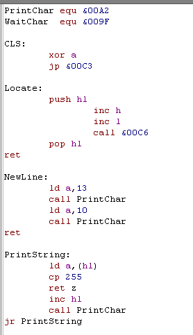
| The Spectrum gave us a hard time,
but the MSX is much kinder! PrintChar is handled by firmware call &00A2 WaitChar is handled by firmware call &009F CLS has a firmware call of &00C3... but it requires us to set A to Zero for it to work right. Locate is also handled by a firmware call, and like the CPC, the top corner is (1,1) - so we INC H and L NewLine on the MSX is Chr(13)+Chr(10) (Carriage return + NewLine) PrintString is handled simply with the PrintChar firmware call.... and we're done! Simple! |
 |
| The MSX Operating
system makes development really quick and easy! It does have disadvantages in places.. with regards to speed and memory usage... but for this job of getting started, it's great! |
 |
 |
Basic Text Functions on the TI-83: |
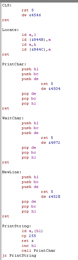
| Being the most limited system, it's
no surprise the the TI-83 has some strange stuff in store
for us! On the TI-83 we use RST 5 to call firmware functions - on the TI it's called BCALL - it pages in firmware rom and calls the address stored in the two bytes after the command... we're going to need it a lot! That said, it's pretty easy to make it do what we need - we just need a lot of PUSH POP's to protect our registers! CLS is handled by the firmware function called ClrScrnFull at &4546... notice we refer to it in a DW after the RST 5 ... this is how we make the TI-83 BCALL a function Locate is unique on the TI too! The current cursor position is held in to memory addresses, we just load the new values into those addresses and we're done! PrintChar is done by firmware function PutC at &4504 and WaitChar is handled by GetKey at &4972... we also use this for out PrintString command! Newline is not done by any kind of character printing... the firmware has a special command for that too! NewLine function &452E does that nicely! And that's it!... the firmware has handled all our requirements very nicely! |
 |
 |
The TI-83 is
the most basic system we develop for... but if we can make
something work with the TI-83... we can probably do it with
anything! it's like our 'Canary'... if our code doesn't die on the TI... it's probably well designed! |
 |
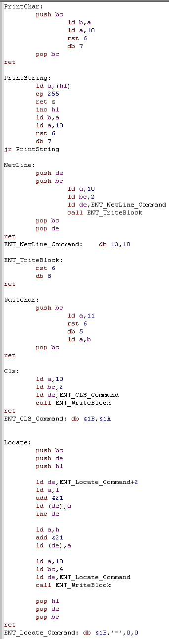
Basic Text Functions on the Enterprise: |
| The enterprise is quite similar to
the spectrum way of doing things! It uses Channels to connect to
hardware, and special Charcodes for Text functions This code fragment relies on an INIT routine setting two channels up for us... it assumes a Screen has already been opened on Channel 10 , and Keyboard open on Channel 11... see the source downloads to see how it works! On the Enterprise... RST 6 is the EXOS call... A will contain the Channel, and the command will appear in a single byte after the RST6 PrintChar is achieved by EXOS command 7 (see DB 7)... we load B with the character, A with the screen channel (10) and call RST 6 PrintString is the same, we use EXOS command 7 to print each character as needed Newline on the Enterprise needs CHR 13 and CHR 10 - so we could use PrintChar... but instead we use WriteBlock EXOS command 8... which we need to tell it the number of bytes in BC, the memory address of the data in DE... and of course the channel in A WaitChar reads from the keyboard Channel... which we've defined as 11... EXOS command 5 will wait for a character from the Channel (from the keyboard)... it's returned in B... so we need to move it back to A CLS is done with some special control codes... CHR(27) (&1B) is defined as 'Escape' which tells the hardware special commands are coming!...CHR(26) (&1A) means "Clear the screen and reset the cursor position'... again we use a WriteBlock Command to save some commands Locate is also done with Escape codes... the commands are 'Escape = Y X' where Y and X are the co-ordinates - strangely on the EP128 we have to add &21 to convert our 0,0 based co-ordinates to what the Enterprise wants... then we use WriteBlock to send the string! Complex, but not bad... and EXOS doesn't alter the other registers... so at least no PUSH POPping! |
 |
 |
The 'Channel'
nature of the Enterprise means this takes a lot of code... and
while the Enterprise OS does not corrupt registers... we need
practically all of them to communicate with the OS! Still it does the job nicely, and later we can use a slightly modified version of our Amstrad code to access the screen and keyboard directly! |
And there we go!... Later we'll look at making an example of using these scripts, but I have to finish my Z80 Devkit first... and that's taking a lot of time!
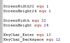
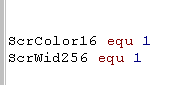
| WinApe can't do very advanced conditions, We would like to do IF ScreenWIdth > 32 as a compiler definition, but Winape won't allow us! So to work around it, we define ScreenWidth32 for IFDEF's, and ScreenWidth as 32 for ranged CP statements. |
|
|
Reading Key input on the ZX Spectrum: |
| On all of our systems, we're going to add some definitions to
the header, We'll need these in later lessons to allow our code to function differently depending on the different systems We're defining screensize functions, and the Keys for Enter and Delete |
 |
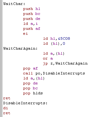
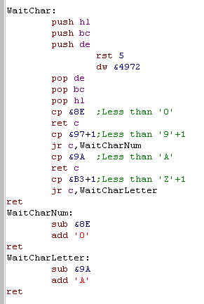
| The WaitChar function we wrote on
the Spectrum last time wasn't great... it often returned 'Command
Characters' rather than letters... so this week we'll change it! This version uses the Firmware updated Variable at &5C08... the firmware updates this each interrupt call. We clear it to 0... then wait for something to be pressed and return it... Of course this would wait forever if interrupts were already disabled... so we use the "PO trick" we learned in Lesson M1... if we LD A,I... PO will be set if interrupts were disabled!... this allows us to turn interrupts on... and back off again if needed! |
 |
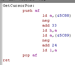
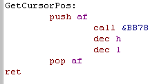
| Here's the new command we're adding this week! GetCursorPos will
return the position text will print next... in the same HL format
as our Locate command! On the speccy we can get these from memory locations &5C88 and &5C89 Unfortunately, for reasons best know to itself, the Speccy stores these relative to the bottom right corner, so we have to do some subtraction to get them in the 'Top-Left' relative format we want! |
 |
|
If we're going
to use IFDEF command, you should make sure the EQU definitions
appear at the top of your code.. or WinApe may get confused! if the definition isn't BEFORE the first IFDEF.. During the first assemble scan, they don't exist, but on the second they do, and WinApe messes up all our labels!!... To Fix it, just put them in the header, before other code, and things will be fine! |
|
Reading Proper letters and numbers on the TI-83: |
| As with the spectrum we define our Screen size, and Enter and Delete keys | 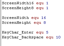 |
| On the TI-83 our GetChar command
was returning all kind of weird things! We need to get proper numbers and letters for future lessons, and a big lookup table seems wasteful! Fortunately, even though they don't map to Ascii.. 1-9 and A-Z are at least consecutive! We can fix these important ranges, just by checking if the keypress is within those ranges, and remapping them to the proper symbols... other keys will still return weird stuff.. but they're not important to us for now! |
 |
| The TI-83 may punish us when keyreading, but the GetCursorPos couldn't be easier!!! | 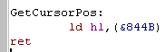 |
|
Getting the Text Cursor Position on the MSX: |
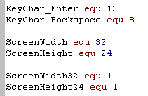
| As with the other systems, the MSX
needs some definitions. However, we have no changes to make to our Keyreader! |
 |
| Our new GetCursorPos command can get the screen location from &F3DC... but it's (1,1) based... so we need to decrease H and L to get the (0,0) base we want! | 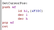 |
|
Getting the Text Cursor Position on Enterprise 128: |
| The Enterprise uses a 40 char wide screen, and a weird key for Backspace, but that's about it for the definitions! | 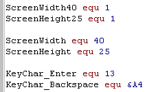 |
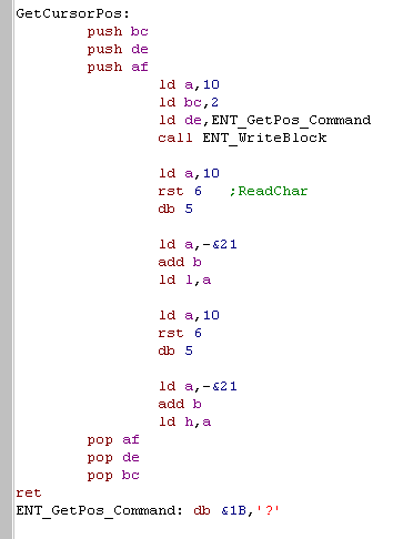
| But it makes us work for our
GetCursorPos! To read cursor pos on the Enterprise, first we send " [ESC] ? " to the screen... then we read two bytes in FROM the screen!!! Re first will be the Y pos, and the second will be the X pos... but like with our LOCATE command... the Enterprise adds &21 to the co-ordinates... We have to subtract &21 from both to get the (0,0) based co-ordinate we want... It's a bit of a 'hassle' but it works fine, so it's all good! |
 |
|
Getting the Text Cursor Position on Amstrad CPC: |
| The CPC is pretty easy, so we've left it pretty much last... Here are the screen and key definitions ! | 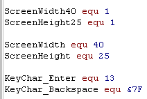 |
| &BB78 on the CPC is know
as TXT_GET_CURSOR - we can just call it and it will return
the cursor position, but we need to decrease H and L, to get the
(0,0) based figures we want. Not much work on the CPC this week! |
 |
And now, Ladies and Gentlemen, tonights feature presentation....
 |
Basic Text functions on the Sam Coupe: |
| The Sam Coupe has a 32x24 screen in it's default text mode, so that's how we'll use it. | 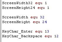 |
| Our INIT routine will load 1 into address &5ABB... this will turn off the 'Scroll' message, the rest of our work will be done by the CLS routine | 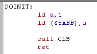 |
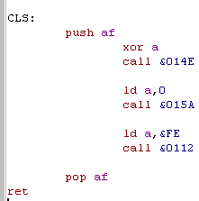
| ... and here it is! &014E is know as JCLSBL... it will clear the whole screen if we set A to 0 next we call &015A .. known as JMODE... we just want text mode so we set A to 0 (Though basic actually calls this mode 1!!) Finally we want our output to go to the screen, so we load A with &FE - known as channel 'S' - the main screen area... A call to &0112 (JSETSTRM) will do the job! |
 |
| PrintChar can be handled by just calling RST 2... but we have to protect a lot of registers! | 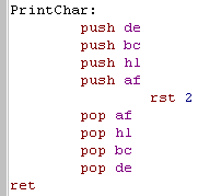 |
| The Sam Coupe just needs a CHR(13)
to start a new line - just like the spectrum! |
 |
| Our Locate command just needs to write it's values to memory addresses &5A6C, and &5A6D... and that's it | 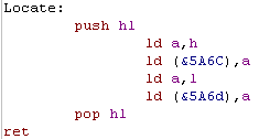 |
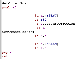
| unfortunately, when we try to get
it back for GetCursorPos.... the Sam Coupe firmware plays a trick
on us! When we do a NewLine... the X position will reset to &FE! How annoying... To fix this, we just check if the Xpos is anything over &F0... and reset it to zero... and the problem is solved! |
 |
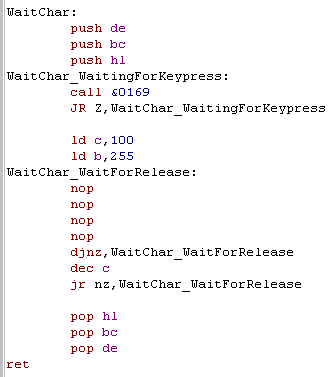
| We're going to call &0169
(JREADKEY) to get input from the Keyboard... this returns NZ when
a key is pressed. Unfortunately(?) it returns very quickly... so we need to pause a bit to make sure we don't instantly read in a load of letters... We could do a HALT, but that would fail if interrupts were disabled, so instead we loop around a bunch of NOP's for a while. Of course we could just wait until the key was lifted again... but we want it to repeat if it's held down long enough! |
 |
| There seem to be
some strange people who consider the Sam Coupe to be a successor
of the ZX spectrum!... because Sam Coupe screen mode 1 is identical to a spectrum... and it's other functions are superior. As it has more memory it can load in a fake ROM and simulate a 48k speccy pretty easily! Fun Fact: the Sam Coupe clocks DOWN to 3mhz from it's usual 6 when in 'Spectrum screen mode'...weird eh! |
|
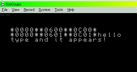
| We'll use these in a later
multiplatform lesson, but lets try a little test program now... See LocateTest.ASM in the samples download! This will show some locations to the screen, then read in text, clearing the screen when BACKSPACE is pressed... and starting a new line on ENTER |
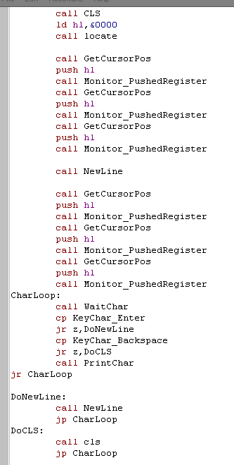 |
| Of course, this little test will
work the same on every system, because it uses our common
functions... But lets see it on the Sam Coupe! the two first lines dump HL from the Get Char Pos, H being the X pos, and L being Y Then we can type our text onscreen, hit enter to start a new line, or press backspace to CLS. We'll do some far better stuff soon using these functions in the Multi-platform Series!!! |
 |
|
The content of this week's lesson may seem boring, but now we have enough to do some proper text reading, and we'll be using these in the Multi-platform series to make some really cool stuff! |
| First lets take a look at the functions we're going to define
for our 'multiplatform
code' The Amstrad CPC and Enterprise have 2 screen modes - one is 4 color, and the other is 16 color, but half the resolution... this code supports either, just enable "ScrColor16" if you want to use the 16 color mode Also, while the CPC & Enterprise support 320x200 at 4 colors, you may want to use a smaller 256x192 screen - which will match the Spectrum and MSX, and will be a little faster! |
 |
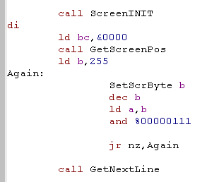
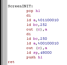
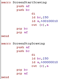
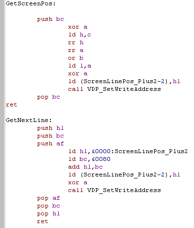
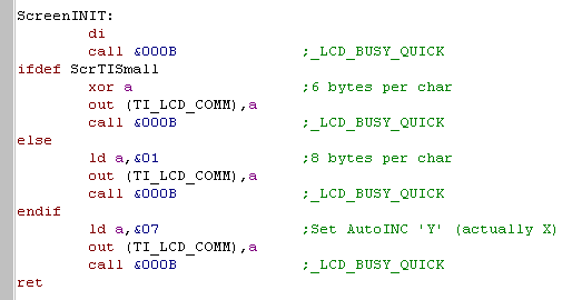
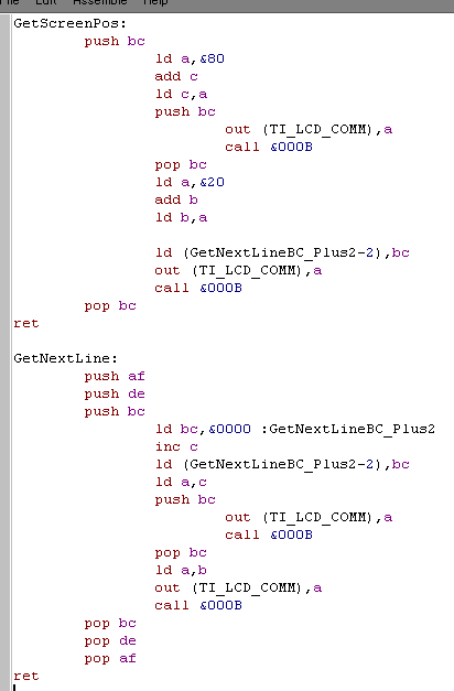
| To start up the bitmap screen we
use the ScreenINIT function. Then we need to select the line we want to send data to with GetScreenPos... we pass it an X,Y co-ordinate in BC... where B is X is in BYTES , and C is Y in LINES Then we can use the SetScrByte to send byte data to the screen (The format must match the system)... the screen position will automatically move along to the next byte in a left->right pattern. When we need to move down a line, use GetNextLine... note the X position is reset to the position when you last used Get ScreenPos. |
 |
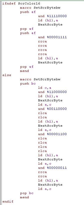
| There is another option... SetScrByteBW will take a 1
bit-per-pixel bitmap (BW) and plot it to the screen, in a common
way on all our systems... we will use this for drawing a common
bitmap font to all our systems! Set ScrByteBW always takes the byte from A! |
 |
| How the data will look onscreen will depend on the system, and color depth you're using! |   |
|
The examples
we're going to look at today work fine, but they're not the
fastest! If you're making your own sprite code or something, you should use these as a template, and create your optimized versions for each platform to get full speed! |
|
Bitmap graphics on the Amstrad CPC: |
| First we need to set up the screen, we can get the firmware to do this, by calling &BC0E, just set A to 1 or 0 depending on the mode you want! | 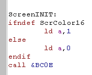 |
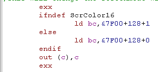
| If you don't want to use the
firrmware at all, you achieve this in a different way! Set B to &7F to send data to gate Array... Set C to 128 plus the mode number you want... and do an OUT command! If interrupts are enabled you'll need to set shadow register BC' to this value... otherwise the firmware interrupt handler will turn it back! |
 |
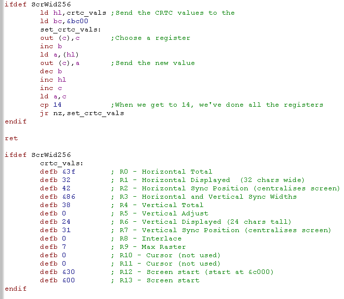
| If you want a 320 pixel wide
screen, you're done! but if you want to work at 256x192 (or
128x192 in mode 0) then there's some more settings needed! We need to define the screen layout, by setting up the 14 CRTC registers of the CPC to resize and re-position the screen! |
 |
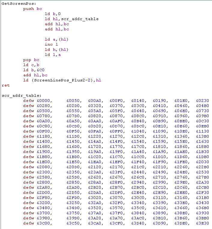
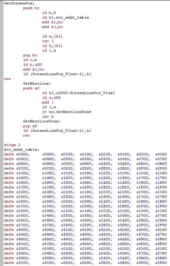
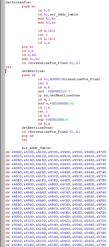
| The first stage of getting data to
the screen is to set HL to the correct memory location onscreen. We use GetScreenPos This example uses a Lookup table to get the screen position based on Y co-ordinate, and then adding the X byte to that... HL will now contain the byte required! Note: if your screen is 256 pixels wide the Lookup table will be different, but the procedure is the same! |
 |
|
Using a lookup
table isn't the only option - and if you're short of memory, you
may want to use an alternative, for example, you could move down
200 times to get the bottom line, or use a formula to calculate
the memory position of a line... A lookup table will be fastest, but if memory is limited, then other options are also viable! |
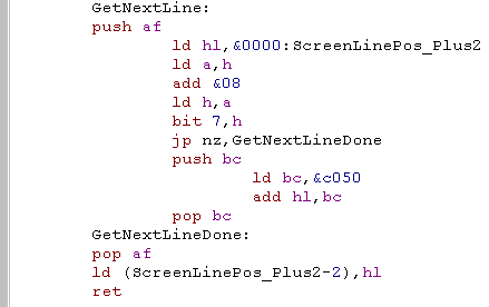
| We will often want to move down a
line, so we can continue drawing a sprite or whatever, we've got a
routine that will do this On the CPC the next line can be calculated by adding &0800 to the byte position... unfortunately, every 8 lines you'll end up going over &FFFF, and need to roll round to &C050... so we check bit 7 to see if this has happened, and adjust if needed... If your screen memory was located at &8000 you would want to use bit 6,h instead. We store the last calculated ScreenLinePos so we can quickly return to the left hand side of our sprite or symbol when moving down a line. |
 |
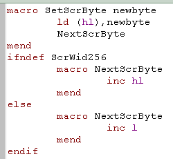
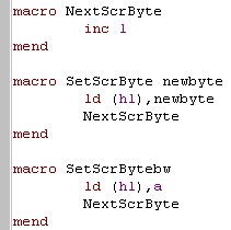
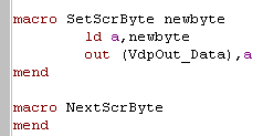
| When it comes to Setting bytes
we're using a Macro... unlike a Call, macros are code fragments
which are inserted by the assembler wherever they are used... we
do this, because the commands could be totally different depending
on the target system, but doing a call every screen byte will be
slow. We're defining SetScrByte to set a byte... and NextScrByte to more along one byte... Note: if we're using 256 pixel wide screens we only need to inc l .. not inc hl... this saves a few CPU cycles so is faster! |
 |
| The last command is SetScrByteBW...
this takes a 2 bit Black and white bitmap, and renders it to
screen in the same format on all of our systems! The bits are organized in L->R format, where bit 7 is leftmost and bit 0 is rightmost (Spectrum format)... on the CPC we have to reorganize the bits quite a bit to achieve this, and in 16 color mode it's even harder! |
 |
|
Bitmap graphics on the Elan Enterprise 128: |
| On the Enterprise the byte data is
the same as the CPC, but the line organization, and setting up the
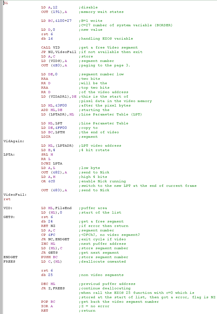
screen is very different The Enterprise can have 128k or more of memory, BUT the screen must be in one of the four first 64k banks.... on the EP64 there are 4 banks FC,FD,FE,FF ... on the EP128 there are 8 banks F8, F9,FA,FB as well as the 4 the Ep64 has What we should do is tell the Enterprise operating system we want 16k memory segments, and until we get back a bank we can use for the screen... then free up all the ones we didn't really want! |
 |
|
Well that was pretty
tough, but we're not done yet! We have to define a table in the memory bank which will define the screen, like the screen, this also needs to be in the first 64k of memory, it's usually pretty small, so it's probably easiest to store it around &CF00 or equivalent with your screen data. |
| The screen definition is called the
Line Parameter Table (LPT)... it's made up of multiple sections. Each "Section" has 16 bytes... 1. The first byte is the negative of the number of lines we're going to define, so if we want 200 lines, it should be -200 2. the next defines the screen mode and other screen options. 3-4. These define the left and right margins of the line... that is, the area used by the screen border. 5-6. These are the memory address of the byte data... note this is relative to the 64k internal banks (FC-FF) not the visible memory to the Z80 7-8. These are unused. 9-16... these are the RGB palette colors... in 4 color mode the layout is (g0 | r0 | b0 | g1 | r1 | b1 | g2 | r2)... so green and red is defined by a 3 bit color definition... but blue only has 2 bits... the remaining 8 colors of 16 color mode are a brighter copy of the first 8 colors, defined by Setting bits 0-4 of "FixBias" on port &80 using out (&80)... we'll look at palettes later! |
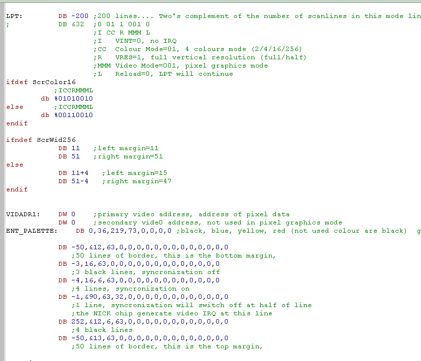 |
| In this example we're just defining one block of 200 lines, and the top and bottom of the screen, but that's just a basic example... if you want you can slice the screen up and add 200 such 16 byte blocks, and change the palette and even screen mode every single line of the screen!... and this is all done by the hardware, so no CPU power is used! | |
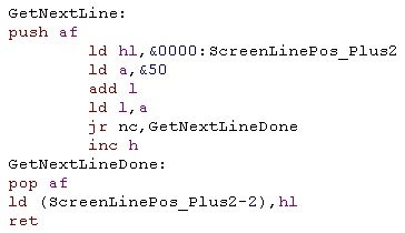
| On the enterprise, getting the next
line is easier because the lines are directly below each other...
as each line is 80 bytes, we just add &50 (Dec 80) to get the
line below... of course it's &40 (64) if your screen is 256
pixels wide. We add to L first... and if it overflows, we INC H... this is faster and uses less registers than doing ADD HL,BC or something like that. |
 |
| SetScrByte , NextScrByte and ScrByteBW are IDENTICAL on the enterprise to the CPC, because the byte layout is identical |
|
Bitmap graphics on the Sam Coupe: |
| On the Sam Coupe the screen is 24k in
size... what's worse, unlike other systems where switchable
banks are 16k in size, on the SAM they are 32k... this makes it
hard for us to access the screen memory with other things... These tutorials will bank in the screen ram in the low half of screen memory - but that means we'll have to use IM2 or disable interrupts |
|
| Our program is running at &8000
, so our only option is to bank in the memory at
&0000-&7FFF... but this means we'll need to change the
stack pointer, and keep interrupts disabled the whole time. As we're going to mess with the stack pointer, we back up the return address in hl first we tell the screen hardware at port 252 what screen mode we want (bits 5-6) and where in memory it is (bits 0-4) then we page in that memory using port 250 where bits 0-4 define what memory appears at &0000-&7FFF Finally we set up a new stack pointer, and put the return address back!... phew! |
 |
| GetScreenpos and GetNext line on
the SAM are basically the same as on the Enterprise... Unlike the CPC the SAM's screen lines are directly below each other, so each as each pixel is 4 bit, and each line is 256 pixels, each line is 128 bytes... To move down a line we add &80... and if L overflows we inc H as well. |
 |
| The Byte commands are the same as the enterprise, not too much to see here! | 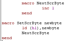 |
| The SAM coupe screen byte layout is not the same as the CPC! two consecutive bits in mode 0 are ------12... on the SAM these are positioned ---1---2... this means we have to do a lot of bit-shifts to get our 2 bit bitmap in the correct format for the screen. as each byte only contains 2 pixels, we have to do this 4 times! | 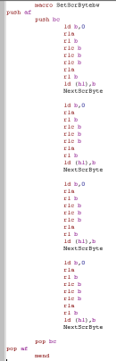 |
| Because of the Sam Coupe's memory
layout if you need to enable interrupts, you'll need to restore
the original low memory bank. I've created two sample macros, which will page in the screen memory, or return the original low memory bank... but be careful! The Stack pointer will have to be above &8000! |
 |
|
Paging in the screen
memory to &0000-&7FFF isn't ideal, but is what we'll do
in these tutorials, When you're writing your own game you may want to bank it into &8000-&FFFF, but as our program runs from &8000 this isn't possible here. We'll cover how to do memory banking in detail in a later lesson! |
|
Bitmap graphics on the ZX Spectrum |
| The screen memory functions on
the ZX Spectrum are similar to what we've seen on the Amstrad
CPC... however unlike the CPC, the Spectrum screen is even more
complex! each 8 lines is spilt into a 'chunk'... and the screen is also split into 3 chunks... and the section of the HL address we need to change varies depending on which of these 'Chunks' we're in. I think this is to make drawing 8 line characters quick - as you can move across the screen with INC L, and down (within 8 lines) with INC H..., but it makes everything else a pain!... the GetNextLine function here will handle it for you, and it's about as efficient as is possible. The bits in HL that make up the XY co-ordinate are shown below:
|
 |
|||||||||||||||||||||||||||||||||||||||||||||||||||
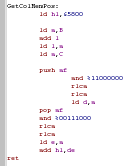
| The ZX Spectrum is basically 1 bit per pixel, but we can
define basic colors for each 8x8 square. To make this easy I've written a GetColMemPos... this will take a location in the same line-byte format as GetMemPos, and will return a byte address in the Color table... The color info on the spectrum is stored from &5800-&5AFF Each Color byte is defined in the following format:
FOREground and BACKground colors are defined by 3 bits each... values from 0-7:
The 'Bright' Bit will make both foreground and background color brighter. |
 |
|||||||||||||||||||||||||||||||||||||||||||||||||||
| The Spectrum may make things
difficult for us when we're getting screen locations, but
because it's 1 bit per pixel, Our Set ScrByteBW command is super
simple!... Also, moving within the X co-ordinate can just be done with INC L.. so everything here is very fast! |
 |
|||||||||||||||||||||||||||||||||||||||||||||||||||
|
Systems like the MSX, Enterprise and Sam Coupe can work in the same way as the spectrum screen... but with only 2 colors per square, the result isn't so great to look at... so in these tutorials we won't be covering those modes... we're aiming for 4 and 16 colors in general, but the spectrum can't do that! |
|
Bitmap graphics on the MSX2 |
|
The MSX VDP (Video Display Processor) handles graphics on the screen of the computer, it works fastest when filling or copying block areas of the screen, however it can also work by addressing screen memory 'bytes' in a similar way to the other systems, while this is rarely as fast as using faster 'area based' commands, it will be sufficient for us to make a start! |
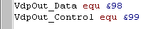
| We access the VDP via it's ports, the main ones we'll need
today are the 'Control' port &99... which we use to
set the memory address in video ram we want to send data to...
and the 'Data' port &98, where we send the new values to
write to memory |
 |
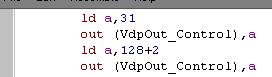
| The VDP has 46 'registers'... these are settings we can set,
and allow us to command the VDP To set one, we typically send the new value we to the Control port, then the register number to assign the value to plus 128.... For example, if we want to set register '2' to 31, we send 31 to the control port, then 128+2 to the control port... The register will now have the correct value! Don't worry if this seems hard, we'll make some functions to do the dirty work! |
 |
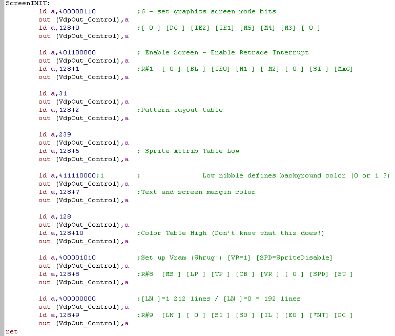
| We have to set a variety of
registers to set up the screen in 16 color mode, don't worry about what these are, as you won't need to change them again! |
 |
|
If you
really want to know the 'ins and outs' of all the options of
the MSX VDP check out the "V9938
-
Technical Data Book Programmer�s Guide" We'll cover some more advanced options later, but if you want to jump ahead, definitely get it and take a look! |
| The MSX 16 color screen has a visible
range of 256x192... however it's 128k vram means internally
it's 256x1024... pixels 193-1024 are offscreen and not usually
show, but we can load sprites into these hidden areas, and
copy them into the visible area, or use this space for
alternate screen buffers... We won't do any of that yet, but its important to know for when we're setting memory addresses! |
|
the MSX screen is 256 pixels wide, Each byte contains 2 pixels, in the same format as the sam coupe, so each line is 128 bytes wide. We're going to use the function "VDP_SetReadAddress" to tell the VDP what memory we want to write to... as the machine has 128k of memory, we won't be able to just use HL to specify the memory address, so we'll use AHL as a 17 bit memory address.. This function will convert the address into the format required by register 14 (direct memory access) so we can start sending data |
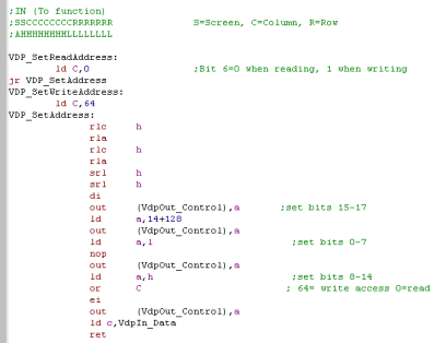 |
| The GetScreenPos function will
convert the co-ordinate to the correct memory address and use
this "VDP_SetReadAddress" command to get the address, When it comes to getting the 'next line' it's not possible to do this automatically, so we recalculate the new memory address, and use the VDP_SetReadAddress again |
 |
| When we want to set the bytes in
video memory, we just OUT the data to the data port (&98) We don't even need to move along one byte, the VDP does that for us! |
 |
| Sending the 1 bit data is pretty much the same, we have to shift the bits around to get them in the correct format for the MSX, but we just OUT the final byte to the screen in the same way! | 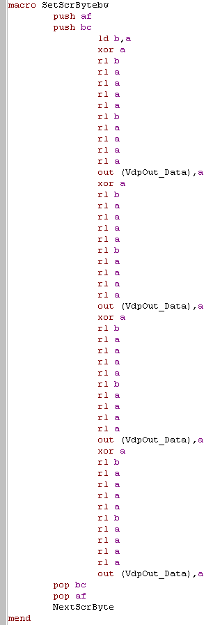 |
|
Bitmap graphics on the TI-83 |
| The Ti-83 uses a command port, and a data port like the MSX,
but that's where the similarity ends! The Ti-83 screen is just 96x64, just 12 characters wide, but it has a 'narrow mode' where only 6 bits of each byte sent are used ,allowing us to use smaller fonts and get 16 characters on a line... we'll support this with the defined symbol 'ScrTISmall' |
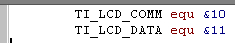  |
| We tell the LCD what we want to do with these ports, unfortunately, it's not very fast, so we have to 'Wait' for it, by calling 'LCD_BUSY_QUICK' at &000B... if we don't things will go strange! | |
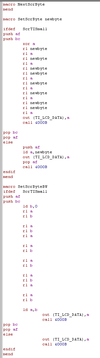
| Our set up is pretty simple, we
just send 0 or 1 to the command port, to set narrow (6 bit) or
normal (8 bit) mode respectively. We send 7 to the screen, this set's what the TI call's 'Autoinc Y' (but everyone else would call Autoinc X)... rather annoyingly in the TI documentation, Y goes across the screen and X goes down! Grr! |
 |
| We set the X,Y position of the
location the next write will appear, by sending 2 bytes to the
command port... We add &80 to the Vertical Y co-ordinate, and send it, and &20 to the Horizontally X co-ordinate - &80 and &20 tell the LCD hardware that these bytes are co-ordinates, not other commands When it comes to moving to the next line, we remember the last chosen co-ordinate and r-eposition the drawing cursor to the line below. |
 |
| If we're just normal bytes to the
screen, we just OUT them to the data port, then call &000B
to wait for the LCD to catch up! If we're using the 6 bit screen mode, then we need to skip 2 bits from the written data, we skip 2 of the middle bits, to try to avoid making fonts look weird! |
 |
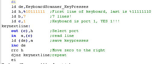
| First we should learn a bit
about the way the keyboards work! The keyboard is made up of two 'membranes'... lets assume each had 8 lines, so 8 on the top membrane, and 8 for the bottom... This would support a keyboard of 64 keys! The line on each membrane goes through multiple keys, but the combination of top and bottom membrane line is unique for each key When a key is pressed, the top and bottom one would make a circuit, and the software would register the key! One strange thing to note... the data we read in will be '1' when the key is not pressed... and '0' when it is...this seems strange, but it's because pressing the key 'shorts' the line |
 A keyboard membrane (Image from Wikipedia) |
 a hypothetical membrane! Lets pretend RED is the top layer's wires, and BLUE is the bottom |
| Unfortunately, because some of the keys share wires, there is a chance a key will 'Clash'.. this is where 3 of the buttons are on the same lines... and the hardware can't tell which of 4 possible buttons were pressed. Even modern keyboards suffer keyclash! | 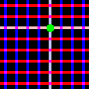 When the GREEN Key is pressed, the membranes join and the hardware registers the key is pressed! |
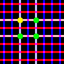 But if the 3 GREEN keys are pressed, the hardware thinks the YELLOW key was also pressed, it can't tell what keys were really down! this is KEYCLASH! |
|
Keyclash
is like life! It sucks, but you just have to make the best
of it! You can't stop it happening, so you just have to pick controls which won't clash too much for your game... for a single player game with one fire, you'll probably be fine, but ChibiAkumas has 3 fires buttons, and simultaneous 2 player... so keyclash is a real problem! |
|
Keyreading on the Amstrad CPC |
| On the
Amstrad CPC, The Keyboard is actually attached to the sound
chip, via the 8255 chip... It's all rather confusing, but fortunately, the 'keyreading' code is pretty standard, we can just copy paste it, and use it for what we need. The Joysticks on the CPC are part of the keyboard... joystick 2 is literally the same as some of the regular keys! |
|
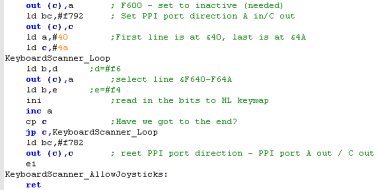
| The PPI has special commands we need to send it &F6C0 will select a register (Registers are settings in the PPI/AY) &F600 sets the PPI to 'Inactive'... we need to do this at certain times to get it to work &F4xx will send data to the PPI &F6xx will recieve data from the keymatrix &F7xx will change the settings of the PPI... we need to do this to change the ports to Read or Write. Again, don't worry too much about this unless you want to change the code, you can just use the code in this example exactly as it is! |
The 8255 PPI:
|
|||||||||||||||||||||||||||||||||||
| FIrst we need to tell the PPI we want to send data, we also get HL ready with our destination for the data. | 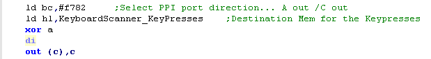 |
|||||||||||||||||||||||||||||||||||
| Now we need to select 'REG 14' of the AY sound chip... the AY actually has some IO ports... and they handle the keyboard! | 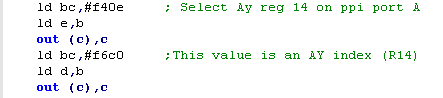 |
|||||||||||||||||||||||||||||||||||
| We set up the PPI so we can read
data in, Now we start reading from lines &40-&4A - which make up all the rows of the keyboard matrix, we use INI which will write them into HL INI also corrupts B on the CPC, but we're resetting it, so it doesn't matter Once we're done we need to reset the PPI port directions. |
 |
|||||||||||||||||||||||||||||||||||
| There is a keymap defined to allow us to convert the keypresses to ASCII | 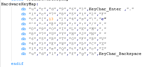 |
The CPC KeyMatrix:
| 0 | 1 | 2 | 3 | 4 | 5 | 6 | 7 | |
| &40 | C-U | C-R | C-D | F9 | F6 | F3 | F-ENT | F. |
| &41 | C-L | CPY | F7 | F8 | F5 | F1 | F2 | F0 |
| &42 | c | [ | RET | ] | 4 | SHIFT | \ | c |
| &43 | ^ | - | @ | P | ; | : | / | . |
| &44 | 0 | 9 | O | I | L | K | M | , |
| &45 | 8 | 7 | U | Y | H | J | N | |
| &46 | 6 J2-U | 5 J2-D | R J2-L | T J2-R | G J2-F1 | F J2-F2 | B J2-F3 | V |
| &47 | 4 | 3 | E | W | S | D | C | X |
| &48 | 1 | 2 | ESC | Q | TAB | A | CAPS | Z |
| &49 | J1-U | J1-D | J1-L | J1-R | J1-F1 | J1-F2 | J1-F2 | DEL |
|
Keyreading on the ZX Spectrum |
|
The Spectrum version is
easier, we just need to understand the port addresses to read in
the keys... Also, with the exception of the Kempson, Cursor and Sinclair joysticks are just keyboard joysticks, so we don't need to do anything special to read them! |
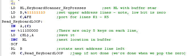
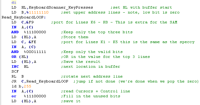
| Keyreading is even easier on
the spectrum, we can just read in the keypresses from the
ports, by setting C to &FE, and all the bits except one in
B to 1.. we then shift this 0 to the left to get the next row! Each line on the Speccy only has 5 keys... so we or %11100000 to fill in the blanks... if we didn't it would cause problems for our multiplatform code! |
 |
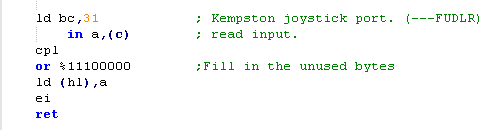
| The Kempson joystick can be
read from port 31 (&1F)... it supports 4 directions and
one fire, though I've heard it's possible to support more fire
buttons... Unlike the keyboard, the bits are inverted, so an unpressed key is 0... and a pressed key is 1, so we do a CPL to make things match the keyboard matrix Again, though, we have to OR %11100000 to ignore any unused keys. A word of warning! reading from port 31 if no kempson port exist will return random data.. so it needs to be disabled by default! |
 |
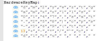
| As with the CPC, We have a defined keymap for ASCII Conversion | 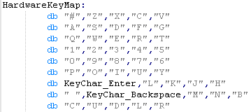 |
The ZX Spectrum KeyMatrix:
| C= &FE | |||||
| B=... | 0 | 1 | 2 | 3 | 4 |
| %11111110 | SHIFT | Z | X | C | V |
| %11111101 | A | S | D | F | G |
| %11111011 | Q | W | E | R | T |
| %11110111 | 1 | 2 | 3 | 4 | 5 |
| %11101111 | 0 | 9 | 8 | 7 | 6 |
| %11011111 | P | O | I | U | Y |
| %10111111 | ENTR | L | K | J | H |
| %01111111 | SPC | DEL | M | N | B |
The Kempson KeyMatrix:
| BC= &1F (31) | |||||
| 0 | 1 | 2 | 3 | 4 | |
| Kempson | J1-R | J1-L | J1-D | J1-U | J1-F |
|
Keyreading on the Sam Coupe: |
| The
Sam
Coupe keyboard is an upgraded version of the Spectrum one!
This allows the SAM to easily emulate a Speccy for games, but
causes os a little extra work when reading the keys, Still, its a lot easier than the CPC! |
|
| The Sam Coupe keyboard matrix is
based on the Spectrum... just with an extra 3 lines added to
each row.. the extra 3 lines are read from port &F9 Our reading procedure is basically the same as the Spectrum, but we have to add in the extra 3 bits from port &F9 We load in the extra 3 lines, store them to the memory address in HL (our buffer) We then load in the other 5, and OR back in the stored value in HL Finally we load in the special line fron &FFFE... this is the cursors and control key. The joystick ports on the sam coupe map to the keyboard matrix too, so we don't need to read them separately... Joy 1 maps to numbers 6-0, Joy 2 maps to 1-5 |
 |
| Once again, we need to define the keymap! | 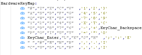 |
The Sam Coupe KeyMatrix: (keys
in Red are same as Speccy... Magenta
are Sam extras)
| Bit-> | C= &F9 | C= &FE | ||||||
| B=... | 7 | 6 | 5 | 4 | 3 | 2 | 1 | 0 |
| %11111110 | F3 | F2 | F1 | V | C | X | Z | SHIFT |
| %11111101 | F6 | F5 | F4 | G | F | D | S | A |
| %11111011 | F9 | F8 | F7 | T | R | E | W | Q |
| %11110111 | CAPS | TAB | ESC | 5 JOY2-L | 4 JOY2-R | 3 JOY2-D | 2 JOY2-U | 1 JOY2-F |
| %11101111 | DEL | + | - | 6 JOY1-L | 7 JOY1-R | 8 JOY1-D | 9 JOY1-U | 0 JOY1-F |
| %11011111 | F0 | " | = | Y | U | I | O | P |
| %10111111 | EDIT | : | ; | H | J | K | L | ENTR |
| %01111111 | INV | . | , | B | N | M | DEL | SPC |
| %11111111 | RIGHT | LEFT | DOWN | UP | CTRL | |||
| Lesson
P7 - Keyreading on the MSX, Enterprise and TI-83 We're going to move on to our other main systems, they are a little bit easier than the Amstrad, but they still have a few tricks for us! |
 |
 |
 |
|
Keyreading on the MSX |
|
On the MSX,
Reading the Keyboard is pretty easy, but reading the Joystick
is pretty tough, We also have to do quite a bit of extra work to avoid messing with the other settings shared by the ports |
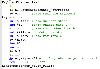
| The keyboard row is selected by
port &AA... bits 0-3 select the row number, but the other
bits have other functions (like Caps LED and cassette), so we
first read in the current state, and set the new keyboard row. To actually read in the keystate of the row we read in from port &A9... then we just move on to the next row! |
 |
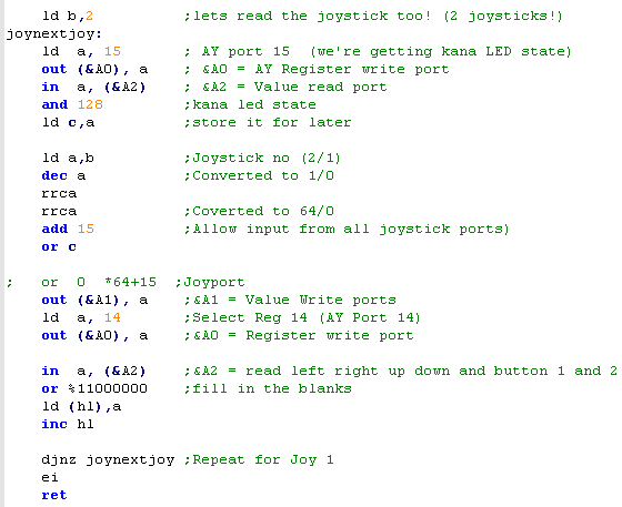
| The Joystick is connected to the
PSG soundchip on register 14 and 15 We control the chip with 3 ports: &A0 - Register Select Write Port &A1 - Value Write Port &A2 - Value Read Port PSG Port 15 selects which joystick to read from - if bit 6 is 1 (64) reading will occur from joystick 2... we should also set bits 0-3 to set the keyboard to read (15) ... Bit 7 also handles the 'Kana LED' on Japanese keyboards.... We read in the state of port 15 to keep the led state... shift the joystick number to set port 6 ... and add 15 to announce we want to read. next we select PSG port 14, and read in the keypresses... bits 6 and 7 are unrelated to joystick reading, so we fill them with 11 We then repeat the whole procedure for the other joystick! |
 |
| The enterprise also has the hardware keymap | 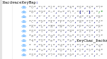 |
Keyboard Matrix:
| &AA | bit 7 | bit 6 | bit 5 | bit 4 | bit 3 | bit 2 | bit 1 | bit 0 |
|---|---|---|---|---|---|---|---|---|
| row 0 | 7 & | 6 ^ | 5 % | 4 $ | 3 # | 2 @ | 1 ! | 0 ) |
| row 1 | ; : | ] } | [ { | \ � | = + | - _ | 9 ( | 8 * |
| row 2 | B | A | DEAD | / ? | . > | , < | ` ~ | ' " |
| row 3 | J | I | H | G | F | E | D | C |
| row 4 | R | Q | P | O | N | M | L | K |
| row 5 | Z | Y | X | W | V | U | T | S |
| row 6 | F3 | F2 | F1 | CODE | CAPS | GRAPH | CTRL | SHIFT |
| row 7 | RET | SELECT | BS | STOP | TAB | ESC | F5 | F4 |
| row 8 | → | ↓ | ↑ | ← | DEL | INS | HOME | SPACE |
| row 9 | NUM4 | NUM3 | NUM2 | NUM1 | NUM0 | NUM/ | NUM+ | NUM* |
| row 10 | NUM. | NUM, | NUM- | NUM9 | NUM8 | NUM7 | NUM6 | NUM5 |
Joystick Matrix:
| Bit | 7 | 6 | 5 | 4 | 3 | 2 | 1 | 0 |
| Button | Casette | JapaneseKeyLayout | Fire 2 | Fire 1 | Right | Left | Down | Up |
|
Keyreading on the Enterprise 128 |
|
The
Enterprise has a fairly simple keymap... the joystick is the
same,it's just read from a different port... however there's a
complication. Reading the basic fire would be simple... but the EP128 actually supports 3 fire buttons, so we have to read in more lines... In fact, in theory the EP128 could support more, but the emulator doesn't cover it, and 3 is probably enough! |
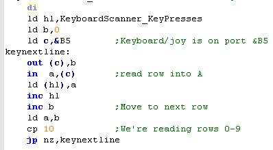
| Reading from the keyboard on the
enterprise is easy! There are 10 rows, from 0-9, we just send the number of the row we want to port &B5, we then read in from port &B5 to get the status of the keys in that row! |
 |
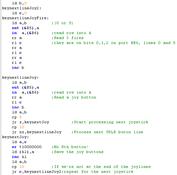
| Reading the Joystick in is also
done from port &B5...however to select the row we use port
&B6! Each row only has 1 bit in use, EXCEPT for the fire button row... which can support up to 3 fire buttons! We shift 3 bits off from the first row, then 1 bit from the next 4 rows... saving the result to HL after setting unused bit 7 to 1 with an or We then repeat the whole procedure for the 2nd joystick... when we get to row 10, we're done! |
 |
| Finally, we have the hardware keymap | 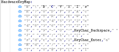 |
Key and Joystick map:
| Row OUT &B5 |
IN &B5 | IN &B6 | |||||||||
| bit 7 | bit 6 | bit 5 | bit 4 | bit 3 | bit 2 | bit 1 | bit 0 | bit 2 | bit 1 | bit 0 | |
| 0 | LShift | Z | X | V | C | B | \ | N | J1-F3 | J1-F2 | J1-F1 |
| 1 | Ctrl | A | S | F | D | G | Lock | H | J1-U | ||
| 2 | Tab | W | E | T | R | Y | Q | U | J1-D | ||
| 3 | Esc | 2 | 3 | 5 | 4 | 6 | L | 7 | J1-L | ||
| 4 | F1 | F2 | F7 | F5 | F6 | F3 | F8 | F4 | J1-R | ||
| 5 | Erase | ~ | 0 | - | 9 | 8 | J2-F3 | J2-F2 | J2-F1 | ||
| 6 | ] | : | L | ; | K | J | J2-U | ||||
| 7 | ALT | Enter | Left | Hold | Up | Right | Down | Stop | J2-D | ||
| 8 | INS | Space | Rshift | . | / | , | Delete | M | J2-L | ||
| 9 | [ | P | @ | O | I | J2-R | |||||
|
Keyreading on the TI-83 |
| The keyboard is connected to port
1 on the TI, we select the row, and read the data back using
this port, Like the spectrum, we set one bit to 0, and the others to 1, to choose the row we want to read. We write this data out, then read in the line contents, and save them to the array |
 |
| As usual we have a keymap. |
 |
| Bwcause on the TI the number and letter keys A-Z use the same keys, we could probably benefit from a second keymap, and some kind of handling of a 'Shift' key, but that's outside of the scope of what we're doing at this stage, right now we're just reading the hardware! | |
Keymap on the TI-83:
| Row Out &1 |
IN &1 | |||||||
| bit 7 | bit 6 | bit 5 | bit 4 | bit 3 | bit 2 | bit 1 | bit 0 | |
| %10111111 | Del | Mode | 2nd | Y= | Window | ZOOM | Trace | Graph |
| %11011111 | Alpha | Math | x-1 | x2 | Log | Ln | Sto | |
| %11101111 | X, T, θ, n | Apps | Sin | , | 7 | 4 | 1 | 0 |
| %11110111 | Stat | Prgm | Cos | ) | 8 | 5 | 2 | . |
| %11111011 | Vars | Tan | ( | 9 | 6 | 3 | (-) | |
| %11111101 | Clear | ^ | � | � | - | + | Enter | |
| %11111110 | Up | Right | Left | Down | ||||


| We
want to do draw the same 'bitmap' as on the regular systems,
but we have to work within the limitations of the TileMap... We could also use sprites, but sprites are more limited in number... and we'll cover them on a later day! |
|
| The Sega mastersystem and Game Gear VDP is very similar to the
MSX GPU... we have to select a video memory address using
the VDP command port &BF... we add &4000 to the
address to tell the VDP we want to WRITE (or add &C000 to
point to palettes) then we send the data low byte, then high ... then we send our data to port &BE to write it to memory... Of course, we need the data to be in the correct format for the destination! |
|
||||||||||||||||||
| On the Gamegear the Pattern data
is 16 colors, on the MSX and Sam Coupe, the memory layout was
simple, each nibble would color one pixel... on the SMS/SGG (and
even 4 color gameboy) things work differently... a byte contains
8 pixels worth of color information, and 4 consecutive bytes
will make up the 'bits' of the 16 colors.... If we think of a color being made up of bits B0 ,B1,B2 and B3... with decimal values of 1,2,4 and 8.... each of the 4 bitplanes will add up to make the colors... the same is true on the Gameboy, however as it's a 4 color system, there are only two bitplanes! |
8
pixels we want to set: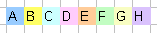 Bitplanes compared to nibbles 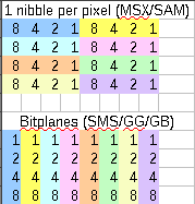 |
||||||||||||||||||
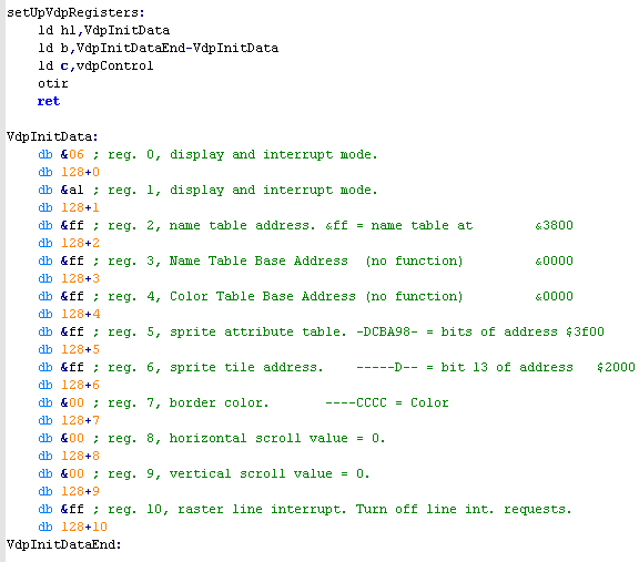
| Firstly we need to initialize the
VDP hardware, and set the 16 color screen mode (the SMS/GG can
also mimic an MSX1!) and set up the default memory
options.... On the SMS/GG we can reposition some of the memory locations, but it's not something we'll need here, so we'll just set everything to the defaults. |
 |
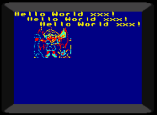
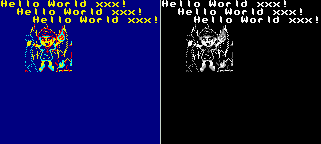
| Here's what our example does...
we will define a font in the first 96 tiles, and use some of the
others to draw the 'Chibiko' Vampire... the Chibiko character is 48x48 pixels, so we fill the area we want to put the image with 6x6 different (consecutive) tiles then set those tiles to the chibiko bitmap data. We're not going to cover the code that draws this example in this lesson, so , take a look at 'GBGG_BmpTest.asm' if you want to jump ahead! |
 |
||||||||||||
| We can create the bitmap data using my 'AkuSprite' editor (included in Sources.7z)... use the SMS function for SMS or GG... the data format is the same! | 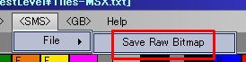 |
||||||||||||
| When we want to send data to the graphics chip we need to send
the address we want to write to to the control port (&BF) The SMS/GG has 16k of ram, so addresses are in the range &0000-&3FFF... however we OR in &4000 ... this tells the VDP we want to WRITE, not read data.... Note if we set the write address to &C00xx... we will define palette color xx (on the gamegear each palette has 2 bytes) |
 |
||||||||||||
| We're going to define the first
64-96 tiles using the 2 color font we used on the other
systems... we set all 4 bitplanes to the same bits - this has
the effect of setting the font to color 15.... |
 |
||||||||||||
| When we want to define 'real' (16 color) tiles, we will need to calculate the tile memory location... we can do this by multiplying the Tilenum by 32 (8 lines, 4 bytes/bitplanes per line =32 bytes per tile) | 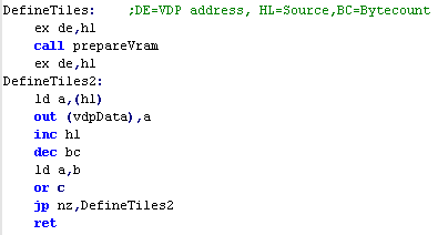 |
||||||||||||
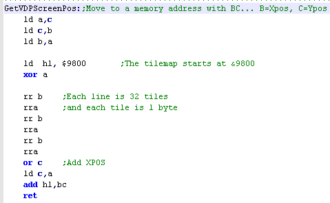
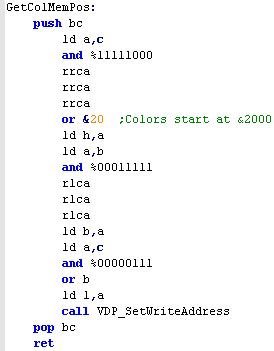
| the GetVDPScreenPos will work
like our Locate command, taking a XY co-ordingate in BC, it will
move the VDP write pointer to the correct position in the Tile
Map This will allow us to simulate a text Locate command... and generally allow tile changes by tile XY, co-ordinate The Tile map starts at &3800, each line is 32 tiles wide... and each tile takes 2 bytes.... Note the X offset of 6, and Y offset of 3 on the GameGear... this is because of the smaller screen of the GameGear... the result is that BC=&0000 is the top left corner on GG or SMS |
 |
||||||||||||
The 2 bytes that define each tile are in the format ---PCVHN NNNNNNNN
|
---PCVHN NNNNNNNN |
|
Note... there are 2
palettes... palette 2 is always allocated to the sprites... but
either palette can be used by the background tiles... We can also have the background go in front of the sprites... but of course there only a single tilemap, so the possibility for parallax is limited. |
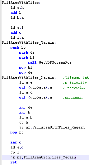
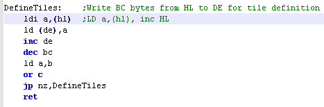
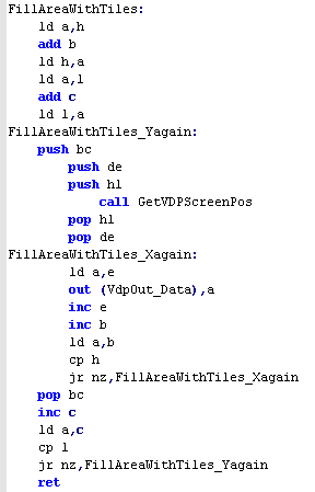
| When we want to draw the Chibiko bitmap, we will use the
'FillAreaWithTiles function... this takes an XY position
in BC, a Width and Height in HL, and a start tile number in
DE... if we call the routine with BC set to &0303 , HL set to &0606 and DE set to 128... the following tiles will be set on screen
|
 |
|
To show my Chibiko bitmap, we just need to set the 36 tiles between 128-163 to the bitmap data of the chibiko bitmap - the AkuSprite editor will do this for us! |
| We've looked
at the tilemap here... but you may need sprites too! Learh about hardware sprites here! |
|


| The Gameboy memory is Memory mapped, so it's part of the
always-accessible area Normal tile definition (pattern) data on the gameboy is stored between &8000-&8FFF. The gameboy uses 2 colors per tile, so each 8x8 tile is 16 bytes... The actual tiles that are shown onscreen are stored between &9800-&9BFF |
|
| The Gameboy
Color actually has a second bank of memory between
&9800-&9BFF! When paged in it allow us to select one
of the 8 GBC palettes - it also allows us to use the extra 256
patterns on the GBC and XY flip the tile, or put the tile in
front of the sprites! However, none of these features are available on the GB! |
|
| Just like the GameGear and
Mastersystem, the Gameboy uses Bitplanes to define it's pattern
and sprite colors from 0-3... this means each line of the
pattern has two bytes. Each byte contains 8 pixels worth of color information, and 2 consecutive bytes will make up the 'bits' of the 4 colors.... If we think of a color being made up of bits B0 ,B1... with decimal values of 1,2.... each of the 2 bitplanes will add up to make the colors... the same is true on the GameGear and Master system, however as they are 16 color systems, there are four bitplanes! |
8
pixels we want to set: Bitplanes compared to nibbles |
| Here's what our example does...
we will define a font in the first 96 tiles, and use some of the
others to draw the 'Chibiko' Vampire... the Chibiko character is 48x48 pixels, so we fill the area we want to put the image with 6x6 different (consecutive) tiles then set those tiles to the chibiko bitmap data. We're not going to cover the code that draws this example in this lesson, so , take a look at 'GBGG_BmpTest.asm' if you want to jump ahead! This example can compile for Gameboy Color or regular Gameboy... On the Gameboy Color the example will use palette 0, on the GB it will use a palette of Black, two Greys, and White |
 |
| We can create the bitmap data using my 'AkuSprite' editor
(included in Sources.7z)... the GB function will save for GB or
GBC... Note Raw Bitmap does not export palette selection... it will use the first 4 colors of the default palette, you'll have to set your palette in ASM if you want to use different colors for different sections of the bitmap |
 |
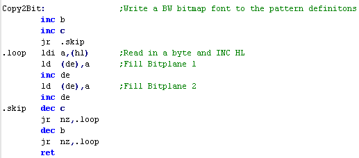
| We're going to define the first
64-96 tiles using the 2 color font we used on the other
systems... we set both bitplanes to the same bits - this has the
effect of setting the font to color 3.... Note, we use the GBZ80 special command LDI, this is the equivalent of "LD a,(hl).. INC HL" in a single command! Of course, this code could not compile for a Z80 system, which is why we won't usually use it, but as this is gameboy only code, we'll use it here |
 |
| When we want to define 'real' (4
color) tiles, we will need to calculate the tile memory
location... we can do this by multiplying the Tilenum by 16 (8
lines, 2 bytes/bitplanes per line =16 bytes per tile)... we then
add &8000, as this is the start of the tilemap memory
address... We just need to copy the memory, but as the GBC has no LDIR command, we have to do the job ourselves! we do however have the LDI command! |
 |
| The GetVDPScreenPos will work
like our Locate command, taking a XY co-ordingate in BC, it will
move HL to the correct position in the Tile Map This will allow us to simulate a text Locate command... and generally allow tile changes by tile XY, co-ordinate The Tile map starts at &9800, each line is 32 tiles wide... and each tile takes a single byte.... The byte data is just a Tile number 0-255, so we write the tile numbers we want to HL after calling this function |
 |
|
That's it
for the Gameboy, but the Gameboy Color has one byte
of extra info! We have to page in the extra rambank, but the address for the extra info is the same as the regular tile! The extra Vram also holds the definitions of tiles 256-511... their memory address is also the same as the regular gameboy's tiles 0-255 |
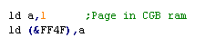
| To page in the GBC VRAM Bank we just write 1
to &FF4f... and to page it out we write 0 to the same
address.. This has no effect on the non color gameboy, but as the GBC data has the same addresses as the Tilemap, we cannot write color data on the regular gameboy, or with no GBC-VRAM to page in, we'd overwrite our tile choices! |
 |
||||||||||||
The meaning of the GBC tile info bits is shown to the right
--->
|
PVH_RCCC |
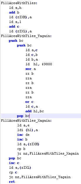
| When we want to draw the Chibiko
bitmap, we will use the 'FillAreaWithTiles function...
this takes an XY position in BC, a Width and Height in HL,
and a start tile number in DE... Note we use zIXH and zIXL... these are temporary stores for data.. the GBZ80 has no IXH or IXL, so we use these as an 'equivalent' Just like the GetScreenPost command, we work out the correct location, and write one byte (a tile number) to each location using the LDI (GBZ80 Load and Increment) if we call the routine with BC set to &0303 , HL set to &0606 and DE set to 128... the following tiles will be set on screen
|
 |
|
To show my Chibiko bitmap, we just need to set the 36 tiles between 128-163 to the bitmap data of the Chibiko bitmap - the AkuSprite editor will do this for us! |
| Need
more than just the tilemap? No problem! Check out this
tutorial here
for spritey goodness! |
|
| The MSX1 VDP memory works
differently depending on the screenmode, but today we'll be
using it in this setup. We need to define Tile Patterns for our Font and Chibiko bitmap, set colors in the Colormap, and define the Tilemap to get them showing onscreen. Patterns are just 1bpp... so 2 color... colors are defined by the Pixel Line... not tile, so each 8x8 tile has 8 color lines... each a single byte containing a foreground and background color (&FB) |
|
| Notice
the
weird 'gap' between &800 and &17FF?.. well the MSX1
can have two extra sets of pattern definitions... although the
MSX1 always uses a tilenumber between 0-255, the screen can
split into 3 'thirds'... each third will use a separate
tilemap (the 2nd at &800 and 3rd at &1000)... this is
how we faked a bitmap mode before! I suppose if you wanted to have your UI in the bottom third (with font definitions and lives etc)... and the top two thirds the playing area (with common tile definitions?) it would work quite nicely! |
|
| Once again, we're showing the
text and Chibiko bitmap... note we've not set any color
information in this example.. If you want to see colored tiles, please take a look at my GrimeZ80 project, which uses this tile code, and Tile color palettes! |
 |
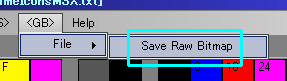
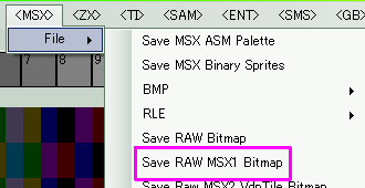
| We can create the bitmap data
using my 'AkuSprite' editor (included in Sources.7z)... For this
example you want to use 'Save
RAW MSX1 Bitmap' This will export the bitmap as a black and white bitmap in the correct order for the MSX1 VDP's tilemap ... however this does not output color information (My Sprite Editor currently has no MSX1 palette support... it was manually entered as data for the GrimeZ80 project) |
 |
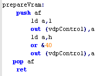
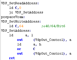
| on the MSX, we have to set up the
VDP's registers so that when we out data to the VDP it will be
written to memory. On the MSX1, we do this by OUTing the HL memory address to the Control port... we add &40 to the address to tell the VDP we want to WRITE not read data. |
 |
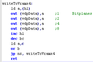
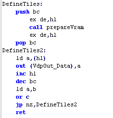
| When it comes to defining tiles,
we just need to specify the source data in HL... the number of
bytes in BC... and the memory destination in DE... As each tile has 8 1 byte line, and the tile patterns start at &0000... We calculate the memory address by multiplying the TileNumber by 8 |
 |
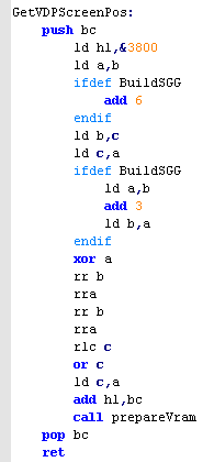
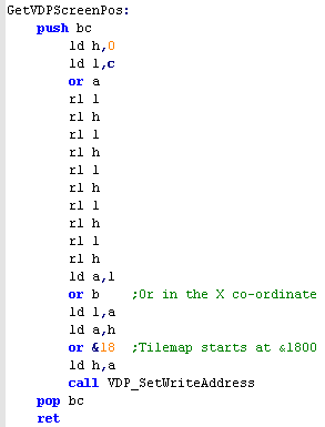
| The GetVDPScreenPos will work
like our Locate command, taking a XY co-ordingate in BC, it will
move HL to the correct position in the Tile Map This will allow us to simulate a text Locate command... and generally allow tile changes by tile XY, co-ordinate The Tile map starts at &9800, each line is 32 tiles wide... and each tile takes a single byte.... The byte data is just a Tile number 0-255, so we write the tile numbers we want to HL after calling this function |
 |
| When we want to draw the Chibiko
bitmap, we will use the 'FillAreaWithTiles function...
this takes an XY position in BC, a Width and Height in HL,
and a start tile number in DE... Note we use zIXH and zIXL... these are temporary stores for data.. the GBZ80 has no IXH or IXL, so we use these as an 'equivalent' Just like the GetScreenPost command, we work out the correct location, and write one byte (a tile number) to each location using the LDI (GBZ80 Load and Increment) if we call the routine with BC set to &0303 , HL set to &0606 and DE set to 128... the following tiles will be set on screen
|
 |
||||||||||||||||||||||||||||||||||||||||||||||||||||||||||||||||||||||||||||||||||||||||||
| This example doesn't use color,
but we have a function to get the correct address location to
write color data... MSX1 color can be set for each 8x1 pixel area (8 pixels wide, 1 line)... we choose a memory location by specifying a XY co-ordinate in BC with a value 0-32 in B, and 0-191 in C Color definitions start at memory address &2000... the 8 lines of color definitions for each 8x8 block are lumped together, so we separate out the last 3 bits of C, and add them last. Each byte defines a foreground and background color... foreground in the first nibble, background in the second... &FB The color palette is fixed, and there are no brightness or other limitations (unlike the speccy!)
|
 |
|
The MSX1's color
graphics are rather odd really, as it uses as much data for the
color map as the bitmap... if you want to see it used 'properly'
please take a look at the Grime
Z80 project... which has line level color info for it's
tiles... of course you can always cheat, and set all 8 lines of a tile to the same color, like ZX spectrum color attributes! |