Learn
Multi platform Z80 Assembly Programming... With
Vampires!
Platform Specific Lessons
<- Back to the Main
Contents & Basic Z80 Assembly Lessons

|
Lesson
P41
-
CRTC Rupture for Interrupt based splitscreen
We're going to take things to another level, and learn how to
exploit the CRTC to do clever tricks...
First we'll take a look at rupture, which allows for CPC
Hardware Splitscreen.
|
 |
CPC_CRTC_Rupture_Interrupt.asm |
|
 |
The CRTC in detail... Know your
Enemy!
We've looked at the CRTC before, but we've not looked at it in enough
depth for what we're going to do now... we need to look at things in a
bit more detail!
Secrets of the CPC screen
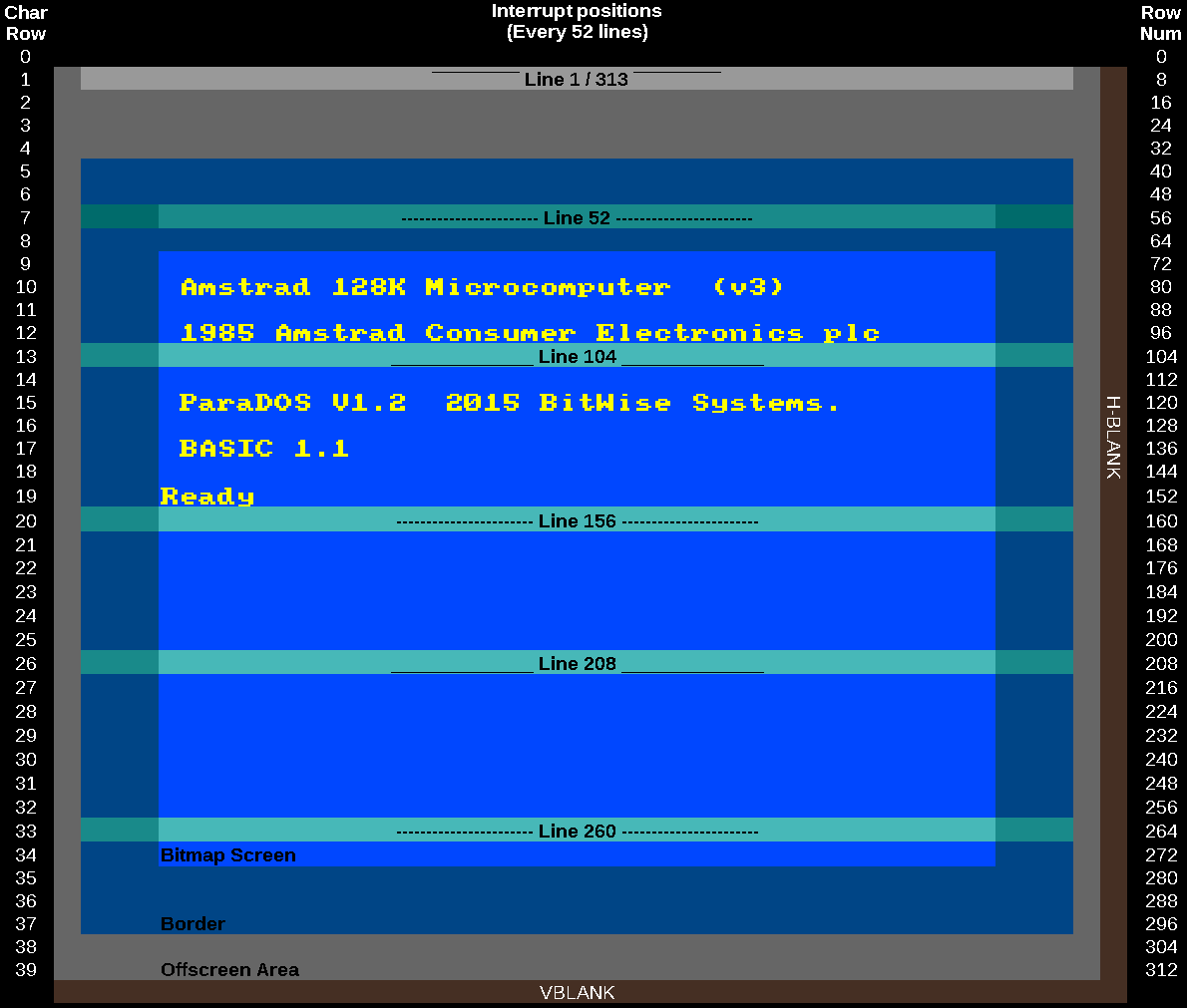
We all know the 'Bitmap Screen'
area of the CPC screen where our text and gameplay occur...
and we all know too well the 'Border' area which doesn't
really do much... but there's some more areas we need to know
about...
As the beam of the CRT draws, the 'Offscreen area' is areas
that are not visible on the screen, above, below or to the
sides of the screen.
the Hblank area is to the right of the visible screen, the
Vblank area is at the bottom...
The screen is divided into 8 pixel tall character blocks... so
the total screen (including invisible areas) is 39 characters
tall
Interrupts ALWAYS occur every 52 pixel lines, so they don't
divide equally to character blocks...
|
 |
While an
interrupt happens every 52 lines, we CAN trick the interrupt
into happening earlier using a trick called RVI (Rupture:
Vertical, invisible)
This combines multiple lines into one, and makes the
interrupt happen faster, but it's VERY complex to get
working, and we can't look at it yet.
|
 |
CRTC Registers
The CRTC has 18 registers we can read and write to, but it also has
some INTERNAL registers that we' can't change, but we can see them
within WinApe, and we'll need to know what many of them do when it
comes to using complex CRTC tricks
It's also important to note that some CRTC chips have limitations that
others do not... we need to try to make sure our code works the same
on ALL CRTC chips
| Reg
Num |
Abbrev |
Name |
Range |
Bits |
Default
Value |
256x192 |
384x272(26k) |
Details |
CRTC
Limitations |
| &00 |
HTOT |
Horizontal
Total |
0-255 |
DDDDDDDD |
63
(&3F) |
63 |
63 |
Physical
width of screen -1 � Leave alone! |
|
| &01 |
HDISP |
Horizontal
Displayed |
0-255 |
DDDDDDDD |
40
(&28) |
32 |
48 |
Logical
width in Chars (8 pixels in mode 1) |
|
| &02 |
HSYNC |
Horizontal
Sync
Position |
0-255 |
DDDDDDDD |
46
(&2E) |
42 |
51 |
Logical
Xpos |
2:
HsncPos+HsyncWid must be < Htot |
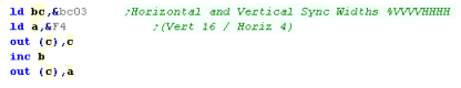
| &03 |
V/HWID |
Horiz.
and Vert. Sync Widths |
0-15,0-15 |
VVVVHHHH |
142
(&8E) |
134
(8,6) |
142
(8,14) |
Hsync /
Vsync area size � Leave alone! |
1+2:
Vhei fixed to 16 |
| &04 |
VTOT |
Vertical
Total |
0-127 |
-DDDDDDD |
38
(&26) |
38 |
38 |
Physical
height
of screen -1 � Leave alone! |
|
| &05 |
VADJ |
Vertical
Total Adjust |
0-31 |
---DDDDD |
0 |
0 |
0 |
Scanline
Offset |
|
| &06 |
VDISP |
Vertical
Displayed |
0-127 |
-DDDDDDD |
25 |
24 |
34 |
Logical
Height in Chars (8 Pixels) |
|
| &07 |
VSYNC |
Vertical
Sync position |
0-127 |
-DDDDDDD |
30 |
31 |
35 |
Logical
Ypos of screen |
|
| &08 |
|
Interlace
and Skew |
0-3 |
------DD |
0 |
0 |
0 |
0/2=off
1/3=on � Leave alone! |
|
| &09 |
MR |
Maximum
Raster Address |
0-31 |
---DDDDD |
7 |
7 |
7 |
Scanlines
per Char row � Leave alone! |
|
| &0A |
|
Cursor
Start Raster |
0-127 |
-DDDDDDD |
0 |
0 |
0 |
unused |
|
| &0B |
|
Cursor
End Raster |
0-31 |
---DDDDD |
0 |
0 |
0 |
unused |
|
| &0C |
DISPH |
Display
Start Address |
0-63 |
xxPPSSOO |
00 /
16 /
32 / 48 |
00 /
16 /
32 / 48 |
12+1
/ 28 /
44+1 / 60 |
PP=Screen
Page (11=C000)
S=Size(11=32k else 16k) O=Offset |
|
| &0D |
DISPL |
Display
Start Address |
0-255 |
OOOOOOOO |
0 |
0 |
0 |
O=Offset |
|
| &0E |
CURH |
Cursor
Address |
0-63 |
--DDDDDD |
0 |
0 |
0 |
unused |
|
| &0F |
CURL |
Cursor
Address |
0-255 |
DDDDDDDD |
0 |
0 |
0 |
unused |
|
| &10 |
LPH |
Light
Pen Address |
0-63 |
--DDDDDD |
0 |
0 |
0 |
Read
Only |
|
| &11 |
LPL |
Light
Pen Address |
0-255 |
DDDDDDDD |
0 |
0 |
0 |
Read
Only |
|
| internal |
VCC |
Vertical
Character
Count |
|
|
|
|
|
Ypos of
drawn line |
|
| internal |
R52 |
Raster
52 interrupt timer |
|
|
|
|
|
Time
since last interrupt |
|
| internal |
HDC |
Horizontal
Display
Counter |
|
|
|
|
|
Current
Hpos |
|
| internal |
HCC |
Horizontal
Character
Count |
|
|
|
|
|
Xpos of
drawn line |
|
| internal |
VMA |
Video
Memory Address |
|
|
|
|
|
Address
of current screenpos |
|
| internal |
VLC |
Vertical
Line Count |
|
|
|
|
|
Line of
character block being drawn |
|
| internal |
VSC |
Vertical
Sync Counter |
|
|
|
|
|
Winape
emulator function � Time synce vsync |
|
| internal |
VTAC |
Vertical
Total Adjust Counter |
|
|
|
|
|
Time
since end of frame |
|
| internal |
HSC |
Horizontal
Sync
Counter |
|
|
|
|
|
Cycles
during Hsync |
|
| internal |
VDUR |
VDU
Raster |
|
|
|
|
|
Winape
Emulator function � offset within display |
|
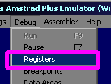
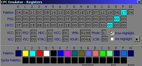
We can see the internal registers
within Winape
Select Registers
from the Debug menu
We can also turn on ROW
HIGHLIGHT - this will show a line on the screen when
the emulator is paused, which shows what the beam is currently
drawing |
 |
 |
 |
Remember,
the Memory address and screen size are only read in at the
start of a new screen, and some tricks (like mode changes and
RVI) need to be synchronized to the end of the line
We'll need to keep an eye on HCC and VCC to do this, and ROW
HIGHLIGHT will help make things more clear.
|
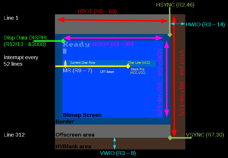
Registers and how they affect the
screen.
The position of the screen, the
borders, and the Vblank locations are all controlled by the
registers,
The current location of the beam is stored in the internal
registers...
The physical size of the screen is fixed, and there are limits
to what the CRTC can do within the screen... but there are
some tricks we can do to exploit the CRTC and get it to do
things it usually wouldn't! |
 |
If
we mess with Hblank or Vblank areas, or VSYNC there's a very
good chance we're going to end up with an unstable screen!
This can also happen if our screen width (HTOTAL) is too
big,
This is just part of the difficulty of these CRTC tricks,
we're going to have to do some of the work of the CRTC
ourselves if we want to do this kind of thing.
|
 |
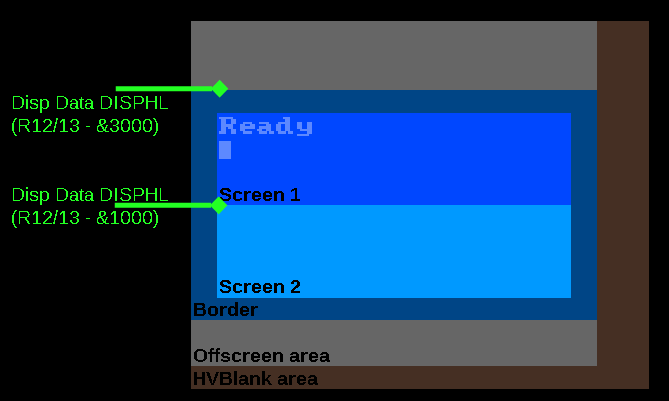
Rupture... two screens are better than one!
We can change colors at any
point during the screen, to get more than 4 colors on a Mode 1
screen (Like in ChibiAkumas)
We saw last week that EGX switches the screen mode every line
to simulate a new screen mode...
But what if we want to have two areas of the screen that
hardware scroll independently? we'd probably want to change
registers R12 and R13 to set the display base... but
unfortunately the CRTC only reads in this address when it
starts drawing the screen...
But we can Cheat!... we define a short screen... then as soon
as it finishes, define a new screen.... this will trick the
CRTC into starting again... re reading in all the registers,
and starting a whole new screen... this is known as Rupture
(also known as Horizontal Rupture)
Unfortunately it's not so easy, we're going to have to trick
the CRTC, and do a lot of the work of laying out the screen
for it... so that we get the screen we want!
Lets take a look! |
 |
Horizontal Rupture... the theory.
There's a few steps we need to do to get Rupture working!
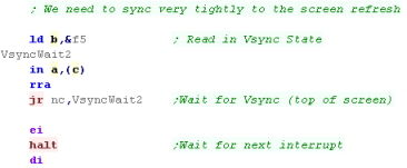
1. Synchronize with
the screen redraw... We need to be very precise in our timing
and change the screen layout during the redraw procedure
2. Set the VSYNC
position (R7) to 255... this is impossible but we need to
stop VSYNC occurring while we're messing... we're going to fire the
VSYNC manually later once we're done
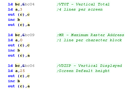
3. Set the height
of the screen in VTOT (R6)
4. Set the Memory
address of the screen (R12+R13)
5. Wait for the beam
to get to the bottom of the screen
6. Repeat from stage
3 for the next screen
7. Once all the screens are done, Set the VSYNC position (R7) to
0... this forces the VSYNC to occur.
8. Wait for the
screen redraw to start again... repeat from step 1
We're going to have to repeat this procedure every single frame the
CPC draws - this is why Rupture is such a pain!
The Rules!
1.The screen must be a total of 312 lines otherwise the screen
won't synchronize
2.Our timing must be precise or we're going to make a mess!
3.A new screen cannot start before an old one ends.
4.Our screen height will be R6 * (R9+1).... R9 is the character height
(usually 8)... we can change this, but setting it to 0 will cause
problems on some screens - it's best left alone at this stage.
We can only set the base address of the screen (in R12,R13) to an
address from &C000-&C7FF... the other areas will be used for
following lines within a character block.
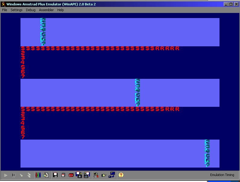
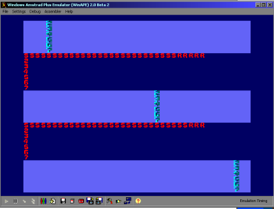
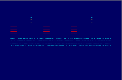
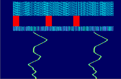
A 'Simple' Example!
We're going to create a simple
example... it will split the screen into 5 sub-screens! (one
per interrupt)
Each screen can have base memory address... and a different
screen mode!... though please note defining screen modes will
slow down your game (just rem them out if you don't need them)
Because the interrupts are handling the stability of the
Rupture effect, you won't need to worry about timing, just
don't disable interrupts!
The example code will show some changing text, and also effect
horizontal and vertical scrolling!
|
 |
 |
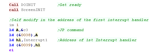
The Code
We're going to need to set things up for the Rupture,
We going to use self modifying code to change the interrupt
handler every time an interrupt occurs...
We load a Jump, and the first interrupt address... Interrupt1
We now turn on interrupts, and start our code! |
 |
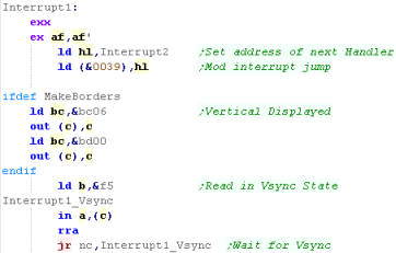
Interrupt 1...
At the start of each interrupt, we self-modify the jump, so the
next interrupt will call Interrupt2 instead
We now have some code which will fake the top and bottom
borders... as we are defining the screen ourselves,
the borders only exists because of this code..
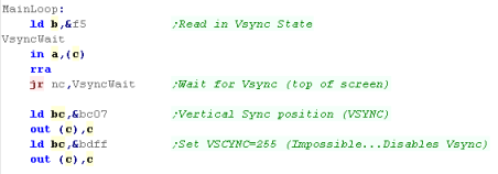
We now need to wait until the screen reaches the VSYNC state,
we do this by checking Bit 0 of port &F5xx. |
 |
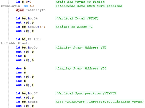
We now wait a little while for
the VSYNC area to finish, and the beam to start scanning the
actual screen... The first part will be the Off-Screen area
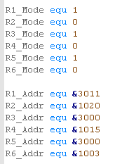
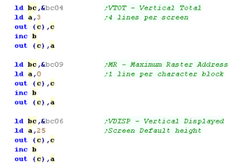
First we want to set the height of the 'screen' (The first
rupture section), we use Reg 4 to do this... we're going to set
this to 4... this results in a screen 5 character blocks
tall.... giving a screen with a total of 5x8= 40 pixel tall
screen
We're now going to set the High and Low Memory addresses using
Reg 12 and Reg 13... the format is a little odd... effectively,
we need to bit shift the top byte by 2 bits, so if we want our
screen to start at &C000 we need to set Reg 12 to &30
(&C0 shifted right twice)...
Note that we're using the settings of R2_Addr here... we're
always defining the settings for the NEXT strip during the
CURRENT interrupt
Finally we're going to set the Vsync position in Reg 7 to 255...
this effectively means VSYNC cannot occur, we'll re-enable it
after our last rupture |
 |
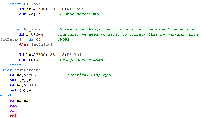
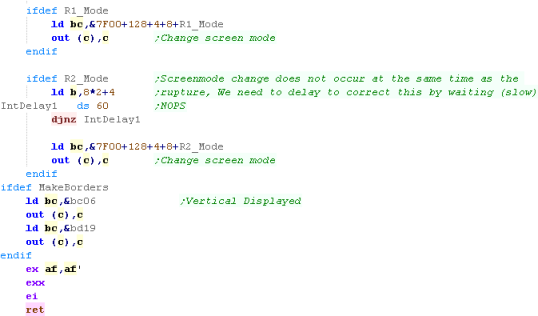
Our newly defined screen will
only start being drawn after the current one completes...
The Interrupt happens slightly before this, which is great for
our splitscreen, but if we want to change Screenmode for the
block, then it won't line up with the rupture...
Unfortunately the only way we can fix this is by making screen
mode changes, then waiting in NOPs... this wastes our CPU power,
but it DOES allow us to align the rupture and screen mode
change.
Once again, if we're simulating screen borders, we now want to
set a proper screen size using Reg 6
|
 |
 |
Now We've
done the first interrupt, we've covered all the complex
stuff... the other 5 interrupts are just using the same kind
of commands to repeat the procedure for another 4/5
'screens'...
Having so many screens is probably excessive, you'd probably
only want 2 in reality... one for your status, and one for the
game - or one for player 1, and one for player 2!
|
| Each interrupt sets the screen settings for the
FOLLOWING interrupt block, so Interrupt 1 sets 2's mode and
address... so if you want to reprogram things you'll need to
bear this in mind... |
 |
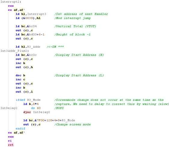
Interrupt
2-5...
Interrupts 2 to 5 are all the same, and just a simpler
version of what we just saw.
Like before, We switch in our new interrupt handler,
Next we define the new screen height with Reg 4
Now ew set the new Screen memory address with Reg 12+13
Finally we wait, then change our screen mode if needed....
Note... there is NO messing with borders, or VSYNC position this
time... those were just for Interrupt handler 1! |
 |
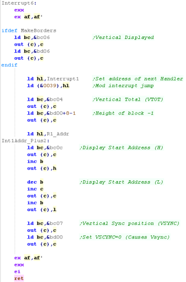
Interrupt 6...
Time for the last interrupt!... it's a little different.
We need to define the next interrupt handler, this time we're
using Interrupt 1
If we want borders, then we want a border to appear , so we
define it with Reg 6
As before we define the height of the block with Reg 4.... the
Screen memory address with Reg 12+13... we've seen this in
Interrupt 2-5
The next bit is different... Now we need that VSYNC to occur...
we want to make the Vsync occur now, so we set Reg 7 to Zero...
The VSYNC will occur, then the settings we just set will be used
for the top of the new screen
|
 |
Different
CRTC versions have different limitations, and some don't like
things other's are OK with... This example should work ok on
all of them...
|
|
|
Lesson
P42
-
Advanced CRTC Rupture
We used Rupture last time to do split-screen, but it's possible
to use Rupture along with other registers to build a visible
screen that is constructed from
Last time all our blocks were the typical 8 pixels tall, This
time we're going to work with 4 pixel strips instead by altering
Reg 9
|
|
CPC_CRTC_Rupture_Advanced.asm |
|
|
Rupture of less than 8 pixels
Many parameters such as Screen address can only change every
screen...but a screen can be any height... even one single
character block, and as we can even change the height of
character blocks we can have whatever we want,
In this example we'll use 4 character blocks just 1 pixel tall!
We'll use 3sets of 4 lines to build up the entire screen - a
full overscan screen is being made from just a few hundred bytes
of ram! |
3 sets of 4 lines used to build screen
 |
While we can set the screen base for the start of each screen,
we can only set the base aligned to one of the original 8 pixel
character blocks... this limits us to addresses like
&C000, &C800, &D000, &D800, &E000,
&E800, &F000, &F800
Of course similar screen bases exist for ranges &0000-3FFF,
&4000-7FFF and &8000-BFFF
|
Resulting screen
 |
We can change the base by 1 character block (effectively a 2
byte horizontal scroll) but due to the limitations of R12 and
R13, it's impossible to start a screen from one line down (for
example &C050 cannot be the start of a screen)
|
CRTC Registers:
|
7 |
6 |
5 |
4 |
3 |
2 |
1 |
0 |
| Reg
12 � DispH |
- |
- |
P |
P |
S |
S |
O |
O |
| Reg
13 � DispL |
O |
O |
O |
O |
O |
O |
O |
O |
P=Page S=Screen-size
(16k/32k) O=Offset
Resulting Screen Address:
|
F
|
E
|
D
|
C
|
B
|
A
|
9
|
8
|
|
7
|
6
|
5
|
4
|
3
|
2
|
1
|
0
|
| Screen
Address |
P |
P |
L |
L |
L |
O |
O |
O |
|
O |
O |
O |
O |
O |
O |
O |
- |
P=Page L=Line
in Charblock (Automatic - Cannot be set) O=Offset
|
|
Because we
can only set the start of the screen to a limited number of
memory locations, it can be difficult to get the screen to do
exactly what we want with R12 and R13...
There is a solution... RVI (Rupture, Vertical - Invisible)...
this creates a mini hidden screen at the start of a line a few
pixels wide... the visible screen then starts on the next line
- effectively manipluating the 3 bits that connot be set with
R12+R13
|
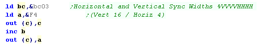
Initialization
We're going to set the Hsync
width as small as we can - this reduces the 'black areas' of the
off-screen parts - and will help stop 'black areas' when we have
an excessive offset
|
Normal Hwid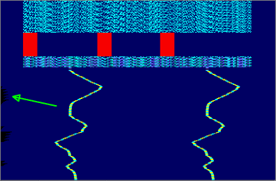 |
Reduced Hwid
|
|
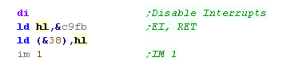
We need to ensure interrupts are controlled, when an interrupt
occurs we're just going to immediately return,
This program is very time sensitive, so our interrupt handler
just returns as quickly as possible |
|
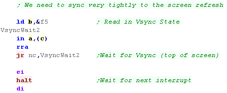
| We need to sync exactly with the screen, we're going to ensure
we're consistently aligned to the interrupts by checking port
&F5 and waiting for a new screen to start. |
 |
The Main Loop
When our loop starts, we need to wait again for the first Vsync
of a new screen...
When the new screen starts, we set the Vsync point to 255 - this
is impossible, effectively ensuring that a Vsync cannot occur
during our drawing of the screen |
 |
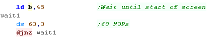
We need to wait a little while for the end of the Vsync,
We will then start defining our physical screen |
 |
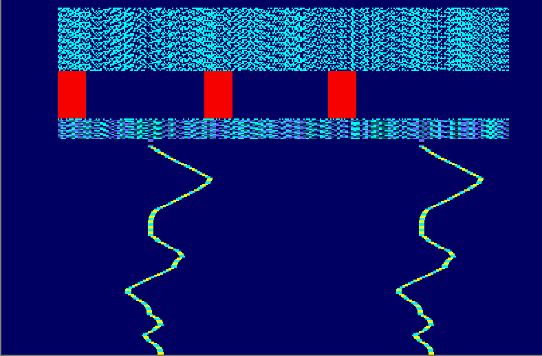
We are going to define some rather odd screens!
Each 'character block' is just one line tall (defined by setting
Reg 09 to &00)...
Each 'Screen' is just 4 character blocks tall (defined by setting
Reg 04 to &03)...
This has the effect of making each screen just 4 pixels tall, and
allows us to change screen address every 4 lines!... because we
disabled Vsync, we can start a new screen after each one of these
tiny screens! |
 |
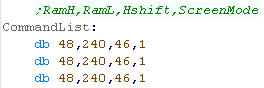
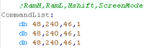
We're going to use a 'Command list' for the main loop,this list
contains entries, one for every 4 pixel tall screen (so 280 lines
in total)
The command list contains 4 bytes...
The first two are the address of the 4 pixel tall screen (loaded
into Reg 12 and 13)... the next is the Hsync position (Reg 2) -
effectively this moves the horizontal position of the 4 pixel
strip onscreen
The final byte is a screen mode - we can change screen mode every
4 pixels if we wish! |

|
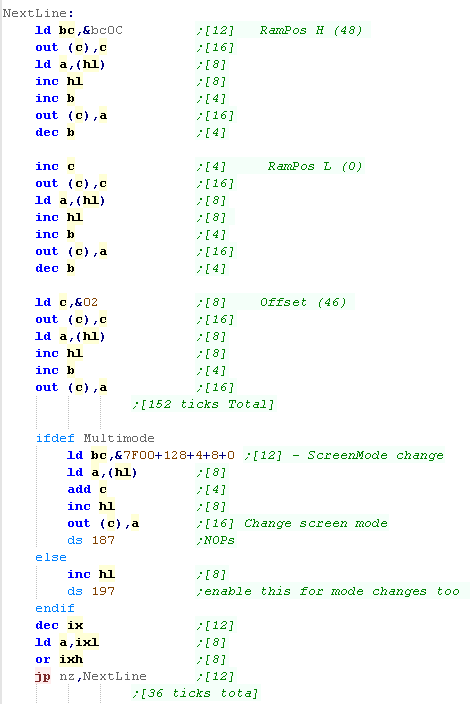
During the main loop, we load each
of the 3 screen parameters, and OUT them to the video registers...
If we 're changing the screen mode, we then Out this to the gate
array...
Once this is done, we perform a delay until the next 4 pixel
screen starts... we define a large number of NOP commands (Byte
&00) with a DS command.
We repeat this whole procedure for every 4 pixel screen. |
 |
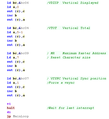
Once the screen has finished
drawing, we need to reset the screen settings so we can cause a
Vsync.
Once we've done this, a vsync will occur, and when it does we can
start the procedure again! |
 |
This
may seem pretty logical, but the trouble is the timing of the 4
pixel tall screen creation has to be EXACT, and it takes all the
CPU time.
If we were making a game, we'd effectively have to fit the
entire game-play code into the NOP sections
|
|
|
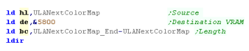
In this
example we'll look at the options of ULA NEXT, this allows the
bits of the color attributes (&5800-&5AFF) to be
reconfigured... alternatively we can just alter NEXT colors
0-31 to change the default colors the regular ULA gives.
|
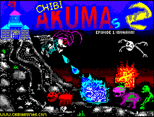
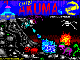
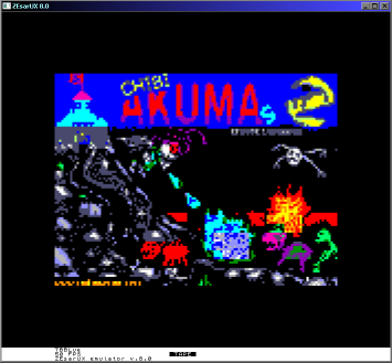
ULA - The options!
Here's our Chibiakumas default screen... this is using the
classic spectrum coloring options!
|
 |
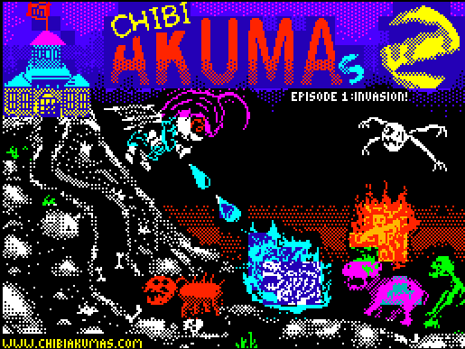
| ULA NEXT Recolor... 3 bit Fore / 4 bit Back (actually 5bit - 1
unused) |
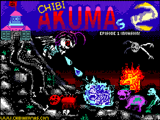
ULANEXT Alt ColorMap... 4 bit Fore / 4 bit Back |
 |
 |
This version has been recolored! 3 bits have been used for the
foreground color, and 4 bits for the background...
We can now select any color from the 256 color Spectrum Next
palette
the result in this case is nicer colors, but the 'dark' colors
have been lost, as we're only using 3 bits for the background...
but the bitmap data is unchanged, so we can easily support ULA+
and classic spectrum with the same bitmap file |
This version has been totally recolored... 4 bits used for
foreground and background - meaning the color information is NOT
the same as the classic spectrum...
We can now use 16 colors for the foreground - and if we want, a
totally different 16 for the background...
Note: This screen was a crude test... a far better screen could
be made with more time and work! |
Spectrum NEXT registers used in this
example
We're going to need a variety of Spectrum
NEXT registers in today's example...
Number
|
R/W
|
Bits |
Default
|
Description |
| &14 |
R W |
RRRGGGBB
|
&E3 |
Sets the "transparent" colour for Layer 2, ULA
and LoRes pixel data. (in RGB) |
| &40 |
R W |
PPPPPPPP |
&00 |
Palette select (0-7=inks , 8-15 Bright, 16-23:
paper, 24-31 Bright paper) |
| &41 |
R W |
RRRGGGBB |
&FF |
Change Palette RGB |
| &42 |
R W |
MMMMMMMM |
&0F |
ULA Next Mode mask (Applied to color attrib...
result is INK entry (umasked bits +128 for PAPER) |
| &43 |
R W |
IPPPSLUN |
&10 |
Palette option P=palette for rw S=sprite L=layer
2 U=ula N=ulanext |
| &44 |
R W |
RRRGGGBB
-------B |
&00 |
Define palette in 9 bits / P=Priority in layer 2 |
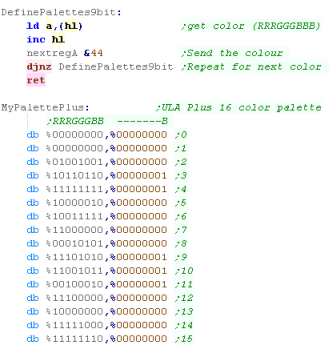
The Key to ULANext is &42 This
defines a set of rightmost bits (Eg %00000111 or %00011111) to define
the INK color number - which is taken from the NEXT Palette... the
remaining bits will be used for the Background color... which is taken
from NEXT palette entries 128+
|
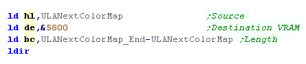
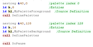
We're going
to use a command called NextReg a lot in this example... it's
a special Z80 opcode added to the processor, we've created a
macro to allow our assembler to support it.
It compiles to db &ED,&91,\reg,\val
|
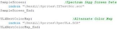
Let's use the NEXT ULA!
In this example, we're going to use the ChibiAkumas screen
shown above, it's been converted to a binary SCR file 7K in
size...
We're also going to use an alternative set of Color Attributes -
768 bytes in size these fill the &5800-&5AFF... and will
replace the classic color attributes with a special one -
allocating 4 bits to foreground colors, and 4 bits to background
- for a 16 color palette...
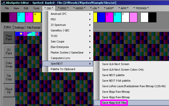
These files were created with my free open source AkuSprite
editor |
 |
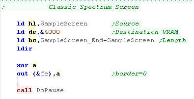
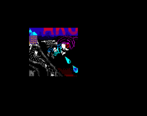
Standard Spectrum Screen:
First we're going to copy the Screen bitmap over the visible
screen (showing the image)
We'll set the border to black, then we'll pause so the user can
see the image.
 |

|
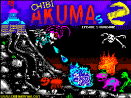
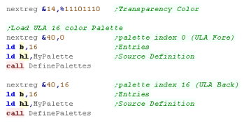
ULANext Relcolored Standard Spectrum Screen:
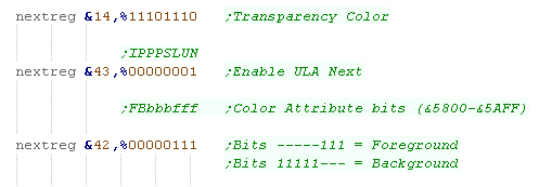
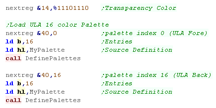
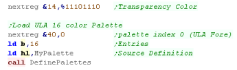
OK, we're going to make some changes - firstly we'll change the
Transparent color with NextReg $14- normally it's bright
magenta, but we may want to use magenta in our palette, so we'll
change it to a different color we won't need
Next we need to enable ULA Next... we do this with bit 0 of
NextReg $43
Now we need to tell the hardware how to use the Color attribute
map... we'll set the Low 3 bits to the Foreground - which
defines the remaining bits as the background |
 |
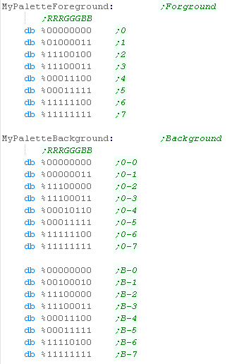
We've allocated 3 bits to our foreground - so we need 8 colors
for our foreground palette (at palette entry 0)
We've allocated 5 bits to our foreground - our picture uses 8
background colors plus the Bright bit (flashing bit is unused...
4 used bits) - so we need 16 colors for our background palette
(at palette entry 16)
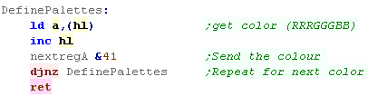
We select the palette entry with NextReg $40 and use a
DefinePalettes function to set the colors |
|
The enhanced version will have nicer color, but we have no
dark foreground colors due to the 3 bit foreground palette
 |
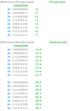 |
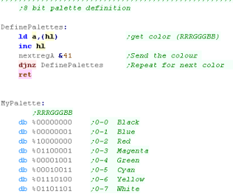
| We've defined a 1 byte per color palette in the format
%RRRGGGBB... we define it by writing color bytes to NextReg $41 |
 |
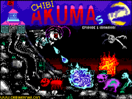
ULANext 4 bit per color Dedicated ColorMap
Spectrum Screen:
We're going improve the colors using a special ULAnext set
of color attributes... we copy the new ULA color info over the
normal one in screen memory
This will result in a total mess on an classic spectrum!
 |
 |
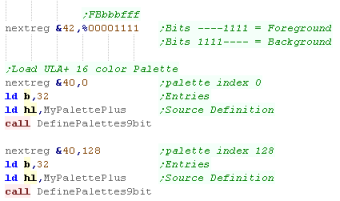
Lets fix that mess!
we need to reprogram NextReg $42 with the new rules!.... 4 of
the bits are our foreground definition... 4 are the background
We need to write the new palette... it's 16 colors, and we've
used the same colors for the foreground and the background... we
use NextReg $40 to select Palette entry 0 for the foreground,
and Palette entry 128 for the background
This time we're using 9 bits per color %RRRGGGBB B so we use an
alternative Palette definition routine (DefinePalettes9bit) |
 |
When we use 9 bit palettes, we write two bytes per color to
NextReg $44... the 9th bit - the low blue bit - is in Bit 0 of
the second byte.
The finished screen can be seen here!
 |
 |
Having
completely configurable 16 colors for foreground and
background adds a lot of potential, but we're still stuck with
the design limitations of 2 colors per 8x8 block.
Still, if we want to support classic Spectrums in the same
code, it's an easy way of giving the game a little improvement
without too much extra work.
|
|
Recolored Classic ULA
| Classic ULA |
Recolored ULA |
|
 |
| The Classic ULA Colors as seen on the Standard Spectrum |
We've used an alternate 16 color palette for the Dark &
Bright colors...
We could have used a different palette for the foreground and
background,
but in this example we've used the same palette for both! |
|
Recoloring
the ULA in this way works far better, and is far easier than
the ULA Next option we looked at last time...
In fact, after seeing this effect, there's not a lot of
benefit to the ULANext option - especially considering the
loss of backwards compatibility
|
The Source Code
on the NEXT The Classic ULA will use the first colors of the
Next Palette
Colors 0-15 will be the Dark and Bright Foreground Colors....
Colors 16-31 are the Dark and Bright background colors... we
select the first color to change with NextReg &40
If we don't want Magenta to be the transparent color, we
probably want to set that to a different color with Reg &14
|
 |
Our palette setting code is the same as last time...
if we're using 1 byte per color, we write to NextReg &41
if we're using 2 bytes per color (9 bit), we write to NextReg
&44
|
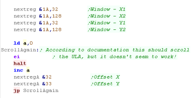
 |
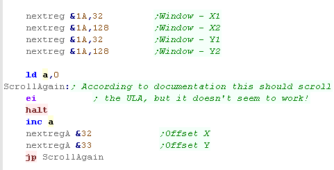
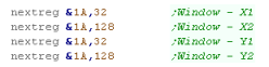
We can hide parts of the ULA with NextReg &1A... four
writes to this address will define a window, hiding the rest of
the ULA
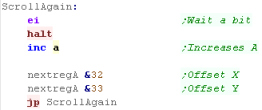
According to the documentation, we should be able to use NextReg
&32 and &33 to define an 'Offset' allowing the ULA to
scroll... it works with LowRes mode, but not the ULA... so maybe
there's a bug in the Emulator?
|
 |
The ULA
offset didn't work as expected when the Author of these
tutorials tried to make it work... maybe he's to dumb to
understand it, or maybe it's an emulator bug or mistake in the
documentation...
But fear not!... When things become clearer, this
documentation will be updated!
|
|
Radasjimian / Low Res Mode
Low Res mode is a linear format,
each line is 128 bytes wide (128 pixels)... and each line is
128... each pixel is 256 color and takes a single
byte... so to move down a line we just add 128
The Screen memory is split into
two separate areas of standard Ram:
Section
|
Lines
|
Ram
|
Top Half
|
0-47 |
&4000-&57FF |
Bottom Half
|
96-9 |
&6000-&77FF |
To the right you can see a re-scaled version of the MSX
chibiakumas screen - though it's only 16 color.
|
 |
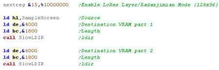
Using Lo Res mode is really easy! All we do is set the top bit
of NextReg &15 - this enables Lo Res Mode...
It uses two &1800 byte large banks of ram at &4000 and
&6000... so to copy our bitmap we do two LDIR commands |
 |
| We set up colors for the LowRes Mode in the same way as usual
on the Next.... in the case of the sample screen, it only uses
16 colors |
 |
We can use Next register &1A to define a 'window' - this
will hide parts of the lowres screen
We can see the result below:
  |
 |
We can scroll the window with the registers &32 and
&33, these set the offset of the layer
 |
 |
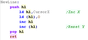
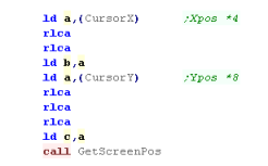
Fonts and Screen Position
When we want to write data to the screen, we can use the
GetScreenPos function... We pass a (X,Y) co-ordinate in BC, and
it returns an address in HL
Because the screen is 128 bytes wide, our formula is:
Address= ScreenBase+Ypos*128+Xpos
if the Ypos is <48 then the Screenbase is &4000, if it's
48 or over then the screenbase is &6000... we move to the
&6000 area by adding &8 to the top byte |
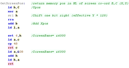 |
| If we want to move down a screen line, all we do is add 128 to
the current memory position. |
 |
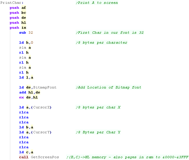
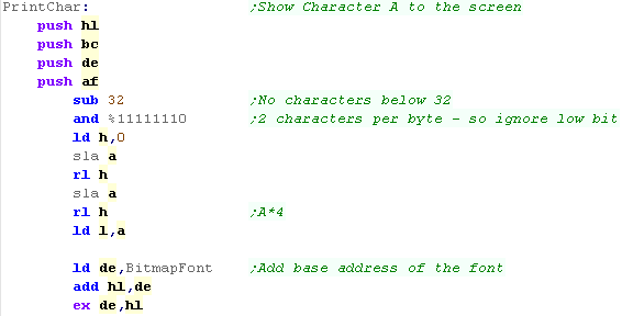
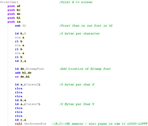
Lets create a PrintChar command - to show the Accumulator from
our bitmap font!
We'll use the 1bpp font we used in the main tutorials... it has
no characters below character 32, and uses 8 bytes per
character...
We subtract 32 from A, and multiply it by 8 to calculate the
offset in our font of the character we want...
Next we load the X,Y pos of the 'cursor' from address CursorX
and CursorY... each character is 8x8 pixels, so we multiply both
by 8, and use GetScreenPos to calculate the address the
character should be printed. |
 |
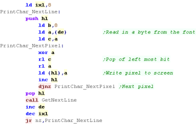
We need to convert our 1bpp font into 8bpp screen bytes... we
do this by reading each byte of our font from DE,
Our Screen address is in HL... we back this up with a PUSH HL
We shift a bit off the left of the byte, and put it into a
screen byte... we repeat this 8 times (with B as a counter)...
we've done one line...
Now we need to do the next line... we restore the old address
with POP HL... and call our GetNextLine function we wrote
We now use IXL as a counter for the 8 lines of our font. |
 |
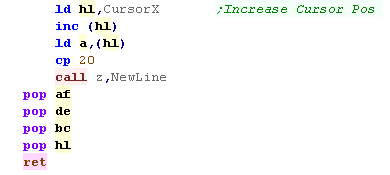
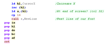
We've printed the character, but we want to increase CursorX
so the next character will be printed to the right of the
last...
we also need to check if we've reached the end of the line, and
move down a line with the NewLine function |
 |
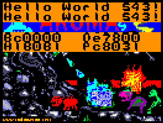
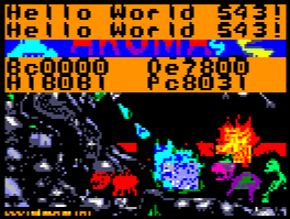
The font is crazy big, but you can see the result here!
for practical purposes, you'd probably want a 5x5 font or
something like that. |
 |
Lowres mode is... well, Low res! but it gives
an extra 256 color layer - so you could use it for a
parallax effect with Layer 2...
We'll look at options for combining layers in a later
episode!
|
|
 |
Lesson
P45
- 256 color mode on the Elan Enterprise
The Enterprise mimics Mode 1 and 0 of the Amstrad CPC... these
provide 320x200 with 4 colors or 160x200 at 16 colors...
But the Enterprise offers an extra mode... 80x200 at 256 color! |
|
 |
 |
|
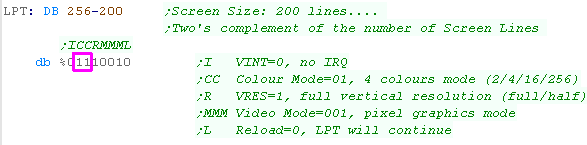
Using 256 Color mode (Mode 3)
| To change the screen mode we need to alter bits 5,6 of
the 2nd byte of the LPT... we need to set these to '3' which
will define the 256 color mode. |
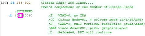 |
| In this mode the 'palette' in the LPT has no effect, and every
byte of the screen ram IS a color definition of the pixel - in
the same format as the palette used. |
Pixel bytes:
| Bit 7 |
Bit 6 |
Bit 5 |
Bit 4 |
Bit 3 |
Bit 2 |
Bit 1 |
Bit 0 |
| G0 |
R0 |
B0 |
G1 |
R1 |
B1 |
G2 |
R2 |
|
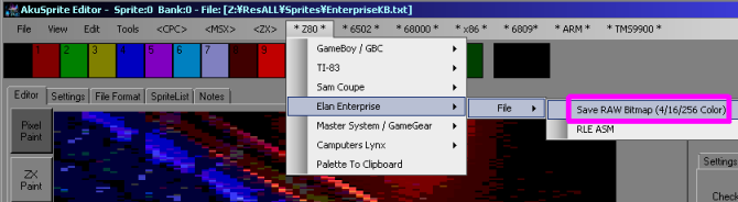
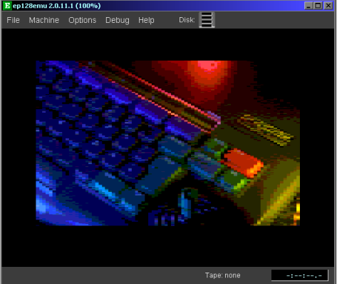
We can see the results to the right!
We can export a valid bitmap with the Akusprite Editor, just
change the view mode to "ENT 80x200 256 color" and use the Save
Raw Bitmap option
 |
 |
|
We're going
to learn how to use a 4 pixel wide 'half nibble' font on the
Enterprise..
This tutorial is based on the 'Simple Hello World' Episode,
and we won't cover again the bits that are unchanged... if
you've not seen that episode, please see it Here
|
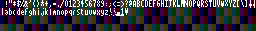
4 pixel wide font for low resolution
screens and saving RAM
Because our screen is pretty narrow, our normal 8 pixel wide
font would just allow 10 characters per line of the screen!.
Instead we'll use just one nibble (4 bits) per character,
halving the total size of our font, down to just 384 bytes for
our 96 character font! |
 |
We call our PrintChar routine to draw a character to the
screen...
Our font has two characters per byte... so when we work out the
byte address in our font for the character, we first ignore the
low bit... we then shift A two times to the left, effectively
multiplying it by 4
We then add the base address of our Btimap font... the result is
DE now contains the address of our character in the font. |
 |
We need to calculate the screen address... we use CursorX and
CursorY bytes to store the next character position...
We multiply CursorX by 4 - as our font is 4 pixels wide... and
CursorY |
 |
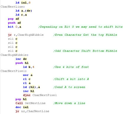
OK, we need to draw our character...
We use IXL as a counter for the 8 lines of the font... we load a
line from the font into C from DE
Next we need to get back the character number we wanted to print
- and see if it's odd or even...
If it's Even, we print the left most 4 bits (the high nibble
%XXXX----)
If it's Odd, we print the right most 4 bits (the low nibble
%----XXXX)... we do this by bit shifting left 4 times with 4x
SLL C before each line...
To convert 1bpp to 8bpp, we shift one bit out of C into A, and
show A to the screen, we repeat this 4 times to show the 4 pixel
wide font...
We use GetNextLine to move our destination HL address in screen
memory down a line, and repeat for the next line of the font. |
 |
| Once we've printed the character, we move the CursorX for the
next character print. |
 |
| We've
used the font here for a half width effect, but if you're
really hard up for ram on a system like the Camputers Lynx,
you could double up the bits in the font, for a 'chunky' 8x8
font, and save 384 bytes of font memory. |
|
Setting up the Tilemap
| First we need to set up the palette... We select the tilemap
palette... then use the DefinePalettes function we wrote before. |
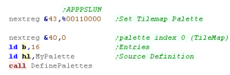 |
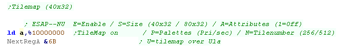
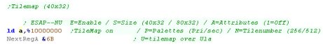
We need to turn the Tilemap on with bit 7 of reg &6B - we
can also specify the size of the tilemap with bit 6 - we're
setting it to 40x32
Bit 5 controls Attributes - when this is 0 each tile is defined
by two bytes (the first is tilenumber, and the second being flip
and palette option)... when it's 1 each tile is just one byte -
the tilenumber... we'll allow attributes! |
 |
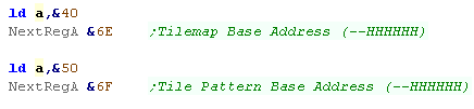
We need to define the address of the tilemap with &6D, and
tile pattern data with &6E
Each uses 6 of the 8 bits - the top two are ignored - the
Tilemap is always in page 5 of ram.
We're defining the tilemap at &4000, and the pattern data at
&5000 |
 |
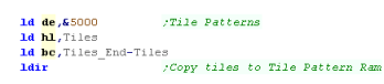
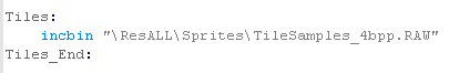
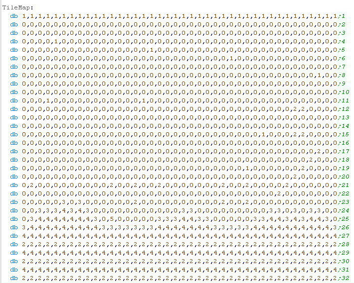
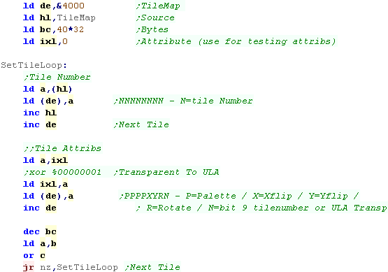
Defining Tile patterns
We define the 'TileMap' which will select the tile number to
show in each position on the screen.
We're going to need to copy this to the correct Ram area in
screen.
With Attributes enabled, Entries in the tilemap take 2 bytes in
the format below:
|
7
|
6
|
5
|
4
|
3
|
2
|
1
|
0
|
Byte
1
|
N |
N |
N |
N |
N |
N |
N |
N |
| Byte
2 |
P |
P |
P |
P |
X |
Y |
R |
U |
N = Tile Number / U
= ULA over Tilemap (or N bit 9) /
R = Rotate Tile / Y =
Y-Flip / X = X-Flip / P
= Palette |
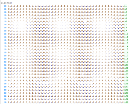 |
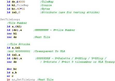
When it come to filling the tilemap, we need to read from our
'Tilemap' label (shown above), and copy the bytes to &4000+
Our tilemap is 40x32, so we set BC to 1280 (&500)
We use IXL to set the second attribute tile for each byte...
really this is just so we can test attributes in this example..
After writing each tilenumber we write IXL - we can filip some
of the bits of IXL after each write if we want to test the
attributes!
|
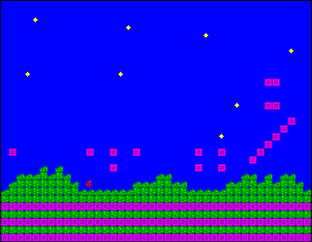
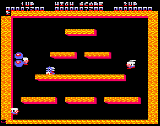
 |
The tilemap will be visible onscreen.
|
 |
Bit 0 of
the attribute can either be 'ULA over tilemap' (Transparency)
or bit 8 of a tilenumber (for 512 tile)... it just depends on
the setting of NextReg &6B
Remember the Tilemap can only be in Page 5 (with the regular
screen) - so if we using the Tilemap AND ULA, we're going to
have too little memory to worry about losing the extra 256
tiles!
|
|
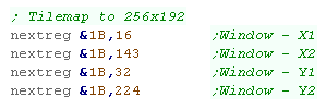
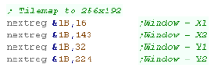
Scrolling and sizing the tilemap
Like with other layers, we
can define a 'Window' to change the visible area of the
tilemap...
By default the Tilemap is bigger than the classic 256x192 ULA,
but we can resize it to match the normal speccy screen |
 |
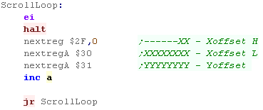
| We can also scroll the tilemap with Nextreg's &2F,&30
and &31 |
 |
| We can scroll and scale the tilemap |
 |
|
The Tilemap
allows us to have good color graphics, and change and redraw
things more quickly than a bitmap layer - so is a great choice
for background graphics in our game - with sprites for our
characters...
We can also use Layer 2 as... well a Layer 2(!) for parallax
effect.
|
|
Lesson
P47-
Using 16 color Mode 0 to simulate 2x 4 color Layers
Some games from the 80's were known to use a trick where the 4
bits of color depth in Mode 0 were split into pairs...
effectively giving 2 layers of 4 colors...
By ANDing and ORing new data in - sprites could change, without
removing the background behind!... Lets check it out!
|
|
CPC_Bitmap_Multilayer.asm |
|
|
|
We're looking
at today's example on the CPC, but the exact same technique will
work fine on any system with 16 colors, and fully configurable
palette.
The Enterprise has 16 colors, however as the 2nd 8 are copies of
the first 8, it's unlikely this trick would work on that system.
|
Working with multiple Layers - The
theory
This concept seems a little odd, and it's probably not the first
one you want to consider for having sprites over background
graphics, but it's at least worth knowing about!
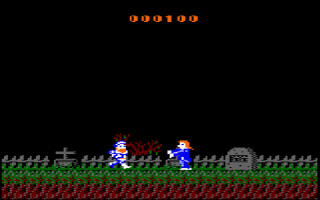
This technique was used in Ghosts n Goblins and Bubble Bobble back
in the 80's
We're splitting the color bits in 2 - so the result is 4
background colors and 4 (possibly different) foreground colors.
Our base Colors for Layer 1 will be Colors
0,1,2,3.... For Layer 2 they will be Colors
0,4,8,12
Colors where the foreground and background overlap
(Colors 5,6,7,9,10,11,13,14,15) will need to be set to the
same color as the foreground layer color (Though we can effect
transparency by using a different color! See Later!)
Color
|
Bits
|
Foreground
Layer Color |
Background
Layer Color |
| 0 |
00 00 |
0 |
0 |
| 1 |
00 01 |
0 |
1 |
| 2 |
00 10 |
0 |
2 |
| 3 |
00 11 |
0 |
3 |
| 4 |
01 00 |
1 |
0 |
| 5 |
01 01 |
1 |
1 |
| 6 |
01 10 |
1 |
2 |
| 7 |
01 11 |
1 |
3 |
| 8 |
10 00 |
2 |
0 |
| 9 |
10 01 |
2 |
1 |
| 10 |
10 10 |
2 |
2 |
| 11 |
10 11 |
2 |
3 |
| 12 |
11 00 |
3 |
0 |
| 13 |
11 01 |
3 |
1 |
| 14 |
11 10 |
3 |
2 |
| 15 |
11 11 |
3 |
3 |
|
 |
ScreenMode 0 uses a weird combination of bits, Each byte has two
pixels - the 8 bits split into two pairs - 4 for the left
pixel, and 4 for the right... we'll need to split them into a
'Layer 1' and a 'Layer 2':
| Bits |
7 |
6
|
5
|
4
|
3
|
2
|
1
|
0
|
| Left
Pixel |
7 |
|
5 |
|
3 |
|
1 |
|
| Right
Pixel |
|
6 |
|
4 |
|
2 |
|
0 |
| Layer
1 |
7 |
6 |
|
|
3 |
2 |
|
|
| Layer
2 |
|
|
5 |
4 |
|
|
1 |
0 |
|
|
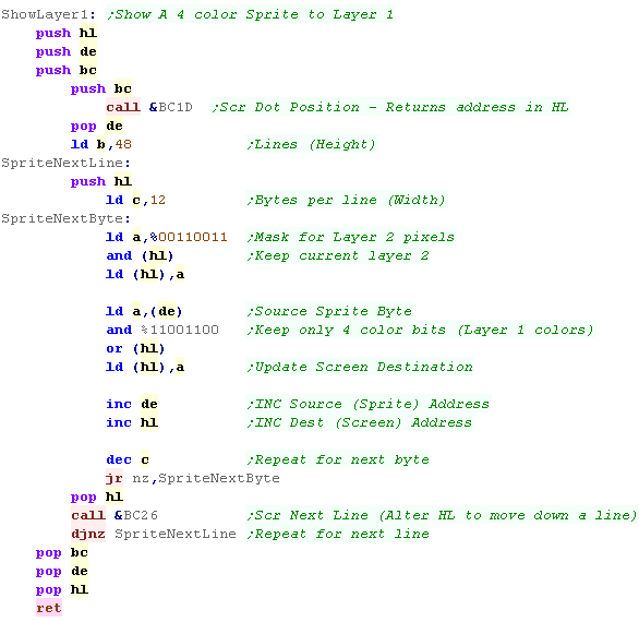
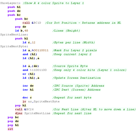
Sprite Drawing Code
We're going to need a pair of sprite drawing routines - one for
each layer.
Here's the version for Layer 1 (the background layer using colors
0-3)
Before writing data to the screen We're going to need to mask the
current screen data, keeping bits %00110011 (the bits for layer 2)
-
And then OR in new new sprite data for layer 1... we AND the
sprite data with %11001100 to make sure there's no extra data in
the sprite... you can skip this if your sprite only has 4 colors.
The code here uses the firmware for screen bitmaps functions. |
 |
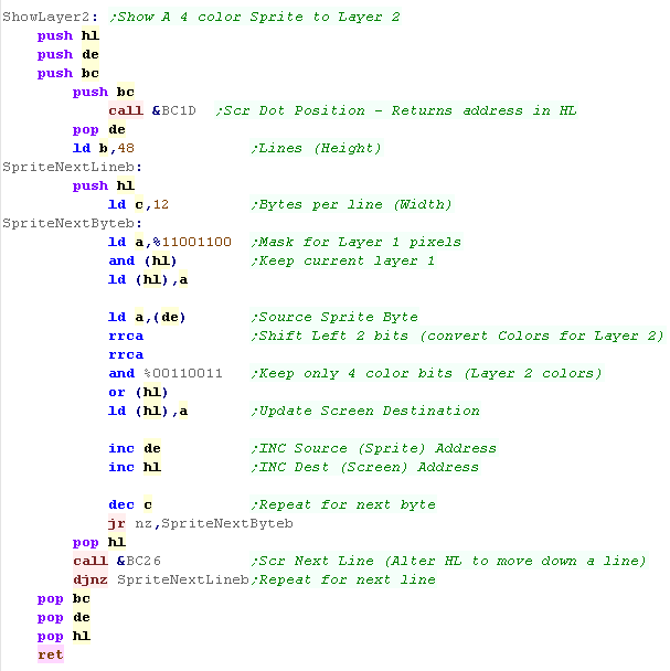
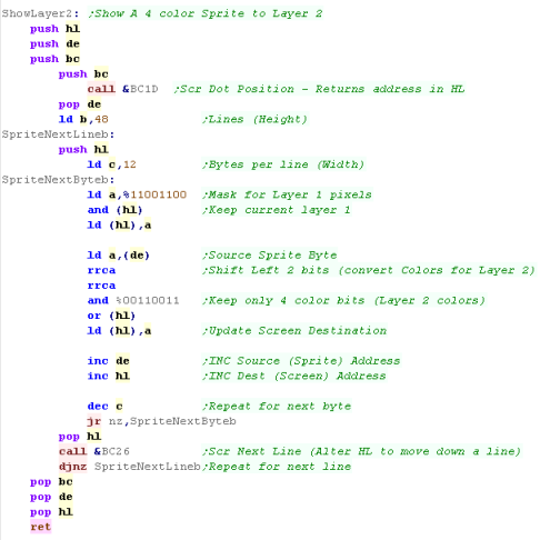
Thre's an alternate version for the foreground layer - the bitmask
for the background has been changed to %11001100 (Keep Layer 1)
We have to bitshift the sprite data 2 bits to the right, to
convert the bitmap for the Layer 2 colors (0,4,8,12)... we mask
the bits with %00110011 to remove any unwanted colors from the
sprite.
|
 |
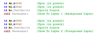
| We can use these functions to draw our sprite to the screen...
we set DE to the Xpos, HL to the Ypos and BC to the sprite data we
want to show. |
 |
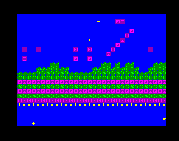
When the two sprites we draw overlap - with color 0 transparent,
the 2nd layer (using colors 0,4,8,12) will take priority,
because of the color palette we've used
If we clear the layer 2 sprite (by writing a blank sprite) ... the
layer 1 sprite will be intact!
The same is true for layer 1 |
  |
If we draw a sprite to Layer 2 and it overlaps an existing
sprite, the layer 2 sprite will be erased!
The same is true for layer 1 |
 |
if we set the Overlap Colors 5,6,7,9,10,11,13,14,15 (The colors
made when the two layers overlap) to a different color - we can
effectively make the layers transparent!
In this example, we've used a palette that will make an 'Anaglyph
3d effect' (Red-Cyan glasses)
Layer 1 is Red shades... Layer 2 is Blue/Cyan shades... The
Overlap colors are Greys and White (Cyan=Green+Blue....
Red+Green+Blue=White) |
 |
Losing half your screen resolution is a high
price to pay, but if you want nice sprites and backgrounds,
and don't want to spare memory on any kind of screen buffers,
it can give you an 'easy' way of moving sprites round the
screen, without having to worry about redrawing your
background.
And it's a bit of fun, don't you think?
|
|
 |
Lesson
P48
- All MSX2 Bitmap Commands - Part 1/2
The MSX V9938 VDP has a wide range of 'Commands'... these will
make the VDP perform a variety of graphics task... depending on
the command, we need to set different registers, and in some cases
we need to check the status registers too...
Lets try each command and learn how they work
|
|
MSX2_Bitmap_AllFunctions.asm |
|
|
Direct Memory access with port &98
Accessing memory directly allows us to write or read bytes
consecutively into VRAM...
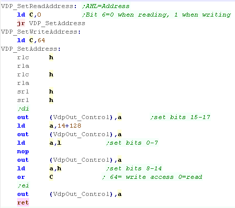
We're going to use the 'SetReadAddress' and 'SetWriteAddress' to
select a VRAM memory address.
The address is specified by registers AHL for addresses from
&00000-&1FFFF... 128k
We have to do some bitshifting, and set bit 6 of byte 3 to either
1 or 0, for Read or Write... we write the result the the control
port (&99) |
 |
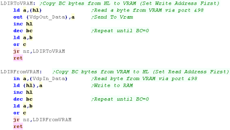
Once we've selected an address, we can read or write to ram from
port &98 (depending on bit 6 of the third byte we sent to the
control port)
We can use this to define a read or write function to transfer
bytes from consecutive addresses in VRAM |
 |
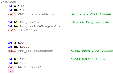
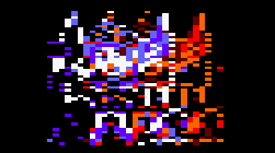
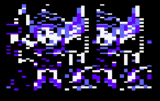
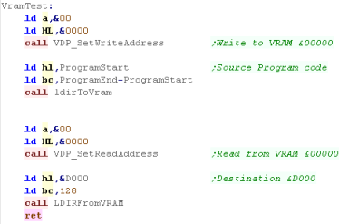
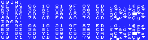
| In this example, we'll transfer part of our game code to VRAM,
then transfer it back to &D000 as a test |
 |
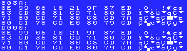
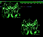
The results can be seen here our code will appear as corruption
(we can see our green sprite in the middle)
If we dump &D000 to screen, we can see it contains the same
data as &803A |

 |
You can use
direct RAM access while the VDP is drawing other things...
ChibiAkumas used this to draw the gradient background while the
VDP was clearing the blank areas.
You can even use VRAM to bank out bits of your program code,
then bank them back in later if you have spare VRAM but too
little RAM... for example you could page out the disk settings
and firmwaer ram at &E000-&FFFF to VRAM during your
game, and bring it back when you load the next lever.
|
|
Common Commands
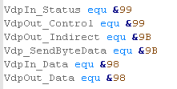
| We're going to need some ports to work with the VDP, and we'll
define them with symbols to make our code easier |
 |
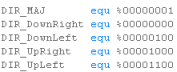
| Many of our functions can take a 'direction'... We're generally
best going left->right,top->bottom, but in cases where there
is an overlap (when we're copying a range to itself - eg a scroll
effect) the order we copy will affect the result... suppose we
copy (x,y)->(x+1,y)... if we work left to right - each line
will be filled with the first pixel... if we reverse the direction
- working right to left, the screen will be scrolled. |
 |
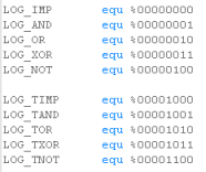
Some of our commands allow 'Logical' functions...
These will allow for operations like XOR, or for 'Transparency'...
when a pixel is color 0
Logical commands are significantly slower, so should only be used
when needed |
 |
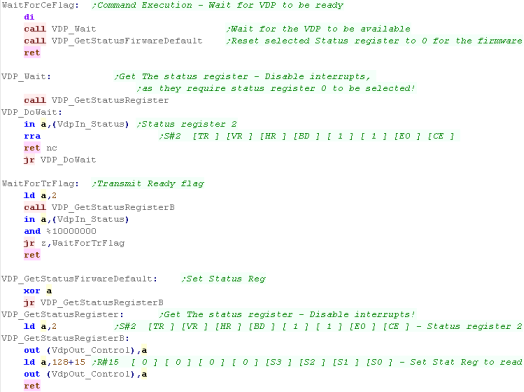
We're going to need to check TR (Transmit Ready - ok to
send/read data) and CE (Command Executing - vdp busy)
To do this we need to Select the status register number with
'normal' Register R15... then we read from the status port &99
to check the status of the register. |
 |
VDP Commands
The 9938 had a wide range of commands, you
can see them below, we'll take a look at all of them!... NOTE: many
commands work with bytes - and X co-ordinates must be even to work
correctly.
|
|
Command |
HMMC |
YMMM |
HMMM |
HMMV |
LMMC |
LMCM |
LMMM |
LMMV |
LINE |
SRCH |
PSET |
POINT |
STOP |
| Register |
|
Purpose |
Fill Vram From CPU |
Fast Copy (Y axis) |
Fast Copy |
Fill |
Logical Fill Vram
From CPU |
Logical transfer
data to CPU
|
Logical Vram to Vram |
Logical Fill |
Line |
Search (Xaxis) |
Pset |
Read Point |
Stop |
| R32 |
SX-L |
Src X
|
|
|
X |
|
|
X |
X |
|
|
X |
|
X |
|
| R33 |
SX-H |
Src X |
|
|
X |
|
|
X |
X |
|
|
X |
|
X |
|
| R34 |
SY-L |
Src Y |
|
X |
X |
|
|
X |
X |
|
|
X |
|
X |
|
| R35 |
SY-H |
Src Y |
|
X |
X |
|
|
X |
X |
|
|
X |
|
X |
|
| R36 |
DX-L |
Dest X |
X |
X |
X |
X |
X |
|
X |
X |
X |
|
X |
|
|
| R37 |
DX-H |
Dest X |
X |
X |
X |
X |
X |
|
X |
X |
X |
|
X |
|
|
| R38 |
DY-L |
Dest Y |
X |
X |
X |
X |
X |
|
X |
X |
X |
|
X |
|
|
| R39 |
DY-H |
Dest Y |
X |
X |
X |
X |
X |
|
X |
X |
X |
|
X |
|
|
| R40 |
NX-L |
Num X |
X |
|
X |
X |
X |
X |
X |
X |
X |
|
|
|
|
| R41 |
NX-H |
Num X |
X |
|
X |
X |
X |
X |
X |
X |
X |
|
|
|
|
| R42 |
NY-L |
Num Y |
X |
X |
X |
X |
X |
X |
X |
X |
X |
|
|
|
|
| R43 |
NY-H |
Num Y |
X |
X |
X |
X |
X |
X |
X |
X |
X |
|
|
|
|
| R44 |
CLR |
Color |
X (first pixel) |
|
|
X (Color) |
X (Color) |
|
|
X (Color) |
X (Color) |
X (Color) |
X (Color) |
|
|
| R45 |
ARG |
Argument |
X (Direction) |
X (Direction) |
X (Direction) |
X (Direction) |
X (Direction) |
X (Direction) |
X (Direction) |
X (Direction) |
X (Direction) |
X (Direction) |
X (Dest) |
X (Dest) |
|
| R46 |
CMD/ LOP |
Command/
Logical Op (x) |
X (&F0) |
X (&E0) |
X (&D0) |
X (&C0) |
X (&Bx) |
X (&A0) |
X (&9x) |
X (&80) |
X (&70) |
X (&60) |
&(5x) |
&(40) |
&00 |
|
|
|
|
|
|
|
|
|
|
|
|
|
|
|
|
| Readable Registers |
|
|
|
|
|
|
|
S7= Pixel Data |
|
|
|
S2=Status
S8/9 = X |
|
S7=Color |
|
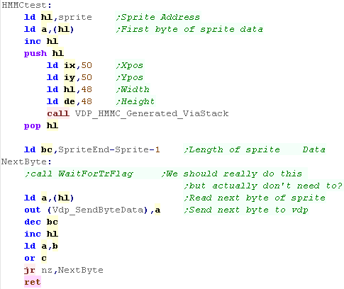
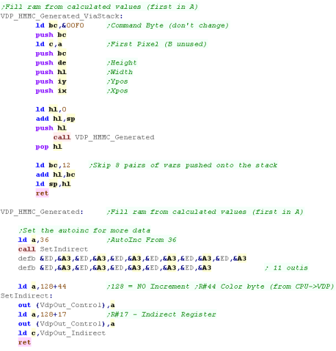
HMMC (High speed move CPU to VRAM) -
Copy data from CPU to VRAM
In this example, we'll transfer data from the Z80 (a sprite in
this case) to VRAM
This will probably be the best way to get sprites from our
disk/cartridge to the CPU
We need to transfer the first pixel with the command... then send
the rest to the VDP data port &99.
We'll select an (X,Y) position, a Width & Height to define an
area onscreen the data will go into.
In theory, We should wait for the TR Flag, but in practice, we
don't need to! |
 |
We need to send data to registers 36-46... we're going to write
11 registers...
We push all the values for these registers on the stack, then use
OUTI commands to send the data to the VDP
We need to set the indirect register to the first register we want
to change (36) before we start our OUTIs... we do this by writing
36 to the control port then 128+17.... the '128+' tells the
hardware to set the register number 17... the indirect register
will autoinc, so we'll write to 36,37, 38 and onwards
This will start the command...
Next we need to select register 44... but we want to stop AutoINC
this time... so we add 128. |
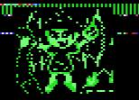
 |
| Our sprite will be transferred from RAM to the screen |
 |
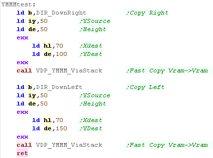
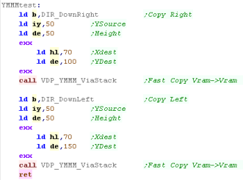
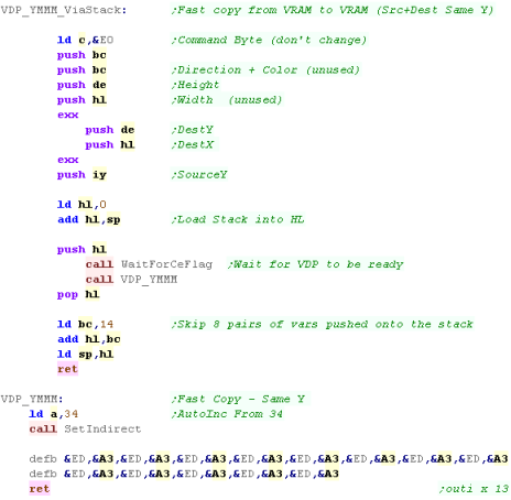
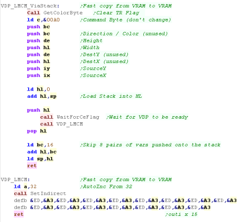
YMMM (High speed move VRAM to VRAM, Y
coordinate only) - Fast Copy (Same Y)
We're going to define a range to copy... Notice we define height
and Ysource... but not Width or Xpos...
Xpos is the same as Xdest... and the width is to the edge of the
screen... this of course means the direction we copy is quite
important!
Because the function is more limited, it's slightly faster than
the normal version. |
 |
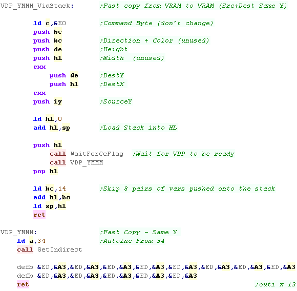
For this command We need to set Registers 34+
Like before, we push all the registers onto the stack, then
execute a series of OUTI's to send the data...
With this command the VDP will start and do all the work itself,
so we don't need to do anything after the command starts... the
Z80 can get on with other work...
But if we want to tell the VDP to start another job we'd have to
check the CE flag to make sure the task has finished |
 |
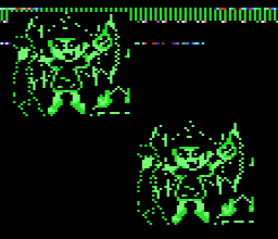
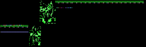
| The result can be seen here! |
 |
The
part of our code which does the OUTI from reg 34 (VDP_YMMM)
doesn't have anything specific to the YMMM command
There will be other commands that also write from Reg34, but
we'll keep separate versions to keep it clear in this example..
If you were using the code in your own program, some
optimization would be a good idea!
|
|
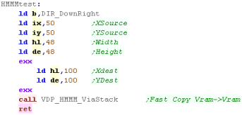
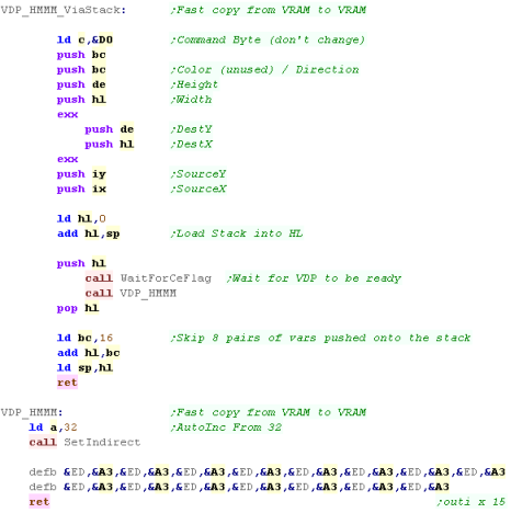
HMMM (High speed move VRAM to VRAM) - Fast Copy
We're going to copy a sprite from VRAM to a VRAM...
During our game this will do most of our sprite copying as it's
fast... however it will delete any background areas - so doesn't
allow transparency (See LMMM) |
 |
Were going to need to fill all the registers from 32-46...
We're going to use the shadow registers for DestX/Y as we don't
have enough registers for the regular parameters |
 |
| The sprite will be copied to a second position onscreen. |
 |
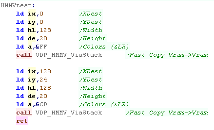
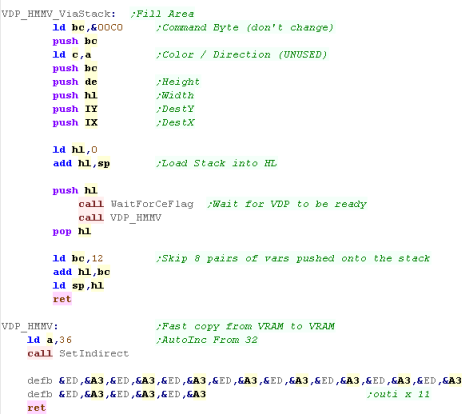
HMMV (High speed move VDP to VRAM) - Solid Fill
The tile is misleading, but this command effectively allows us
to fill areas with a single byte... this is the fastest way to
clear the screen (CLS)
We specify an XY pos for the fill, a width and height and a
color...
|
 |
| The HMMV command needs to fill registers 36+... Like most
commands it does not need any action after the fill starts. |
 |
| The requested areas will be filled. |
 |
|
If the nibbles
of the color bit do not match (in this example &CD) the
filled area will have vertical lines...
It would be nice to have a 'checkerboard' effect... where the
nibbles swapped every other line, but the VDP cannot do this, so
you probably want to just use solid colors (like &CC or
&DD)
|
| |
Lesson
P49
- All MSX2 Bitmap Commands - Part 2/2
We looked at many fast commands last time... this time we'll look
at the 'Logical' commands and a few other strange commands!
While slower, Logical commands allow for transparency!
|
|
MSX2_Bitmap_AllFunctions.asm |
|
|
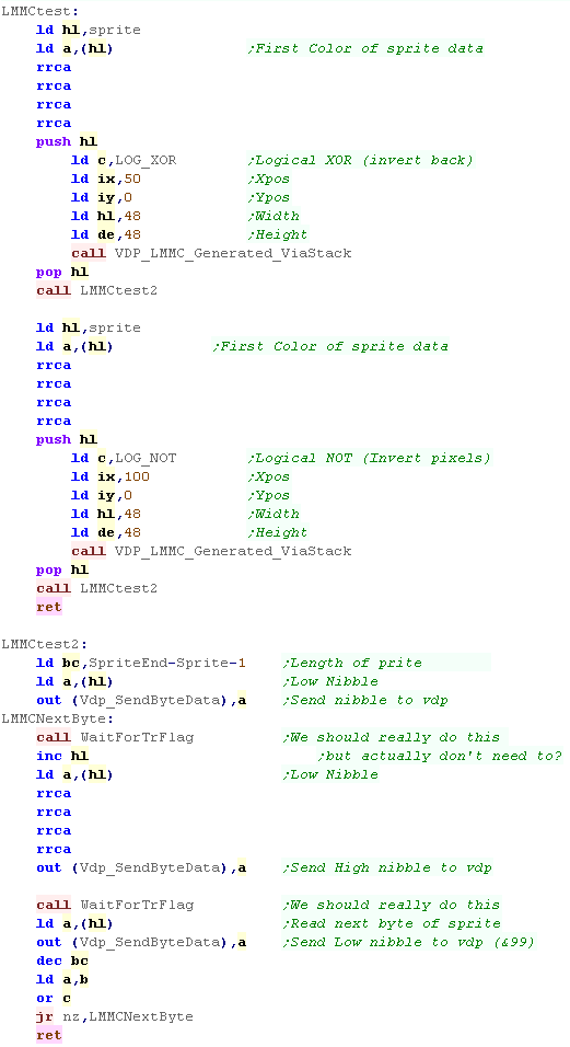
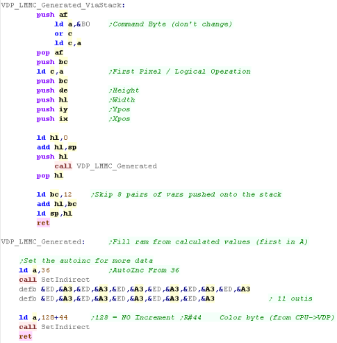
LMMC (Logical move CPU to VRAM) - Copy
data from CPU to VRAM
Like HMMC, LMMC transfers data from Z80 ram to the screen,
but this 'Logical' Version allows an operation to be passed in the
C register...
we're going to test with an XOR (invert background with pixels) or
NOT (Invert pixels)
Logical commands work in pixels, not bytes... so we need to pass
our colors in the low nibble of bytes... this means two writes to
the SendByteData port (&9B) for each byte in HL
|
 |
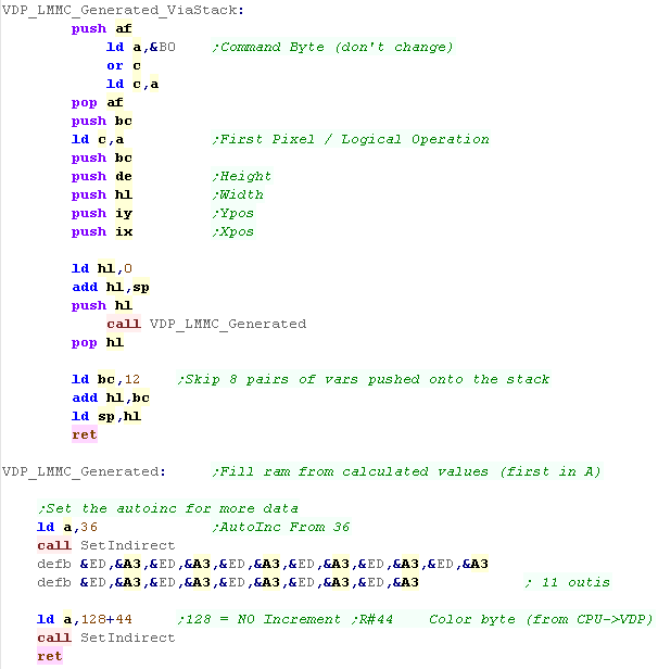
Like HMMC we need to send the values to Reg36 onwards...
Once we've prepare the registers, we need to select Register 44 so
the VDP can recieve the bit data |
 |
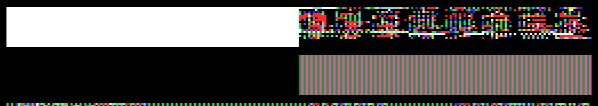
The two versions of the sprite will be shown...
The XOR one will be transparent (but background pixels will be
inverted)
The NOT one will be a color negative. |
 |
|
Logical
operations allow us to perform transparency... but this isn't
really the best way of doing transparency for games... LMMM is
faster as it's VRAM->Vram... we'll take a look at it soon!
|
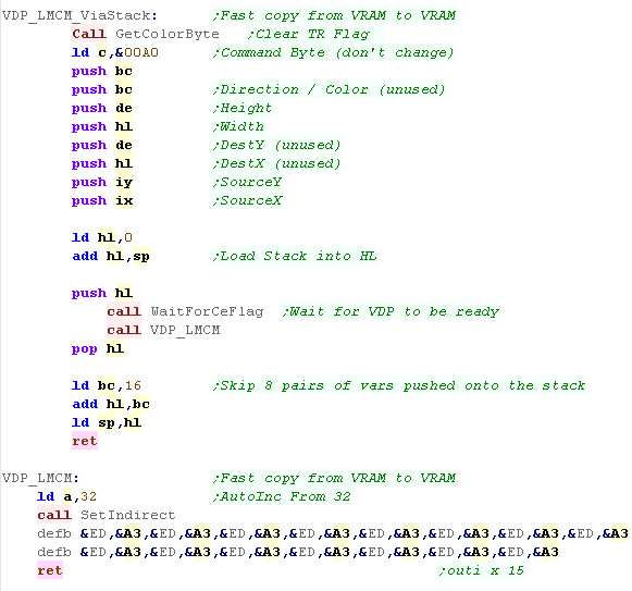
LMCM (Logical move VRAM to CPU) - Read
Pixels from VRAM to CPU
LMCM is the opposite of LMMC... it transfers data out of vram
into the CPU...
BUT... because it's a Logical operation, it copy each pixel - not
each byte...
We can specify an XY start pixel, a Width and a Height...
We can then read in color pixels from Status Register 7... in this
example we'll store them in ram. |
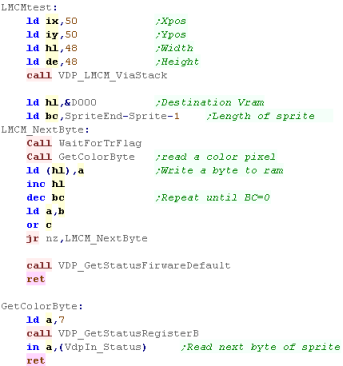 |
For this command We're going to need to populate registers 32+
We read in the colors from Status Register 7. |
 |
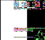
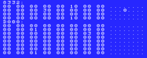
The Sprite was drawn to the screen, and read back to $D000
The data in $D000 will be the same as the sprite (originally at
$8332) except the two nibbles of each byte will be split up...
this is because we read back in PIXELS, not BYTES. |
 |
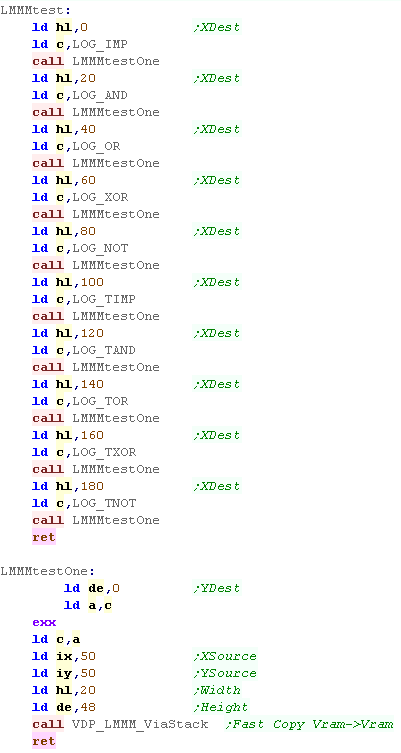
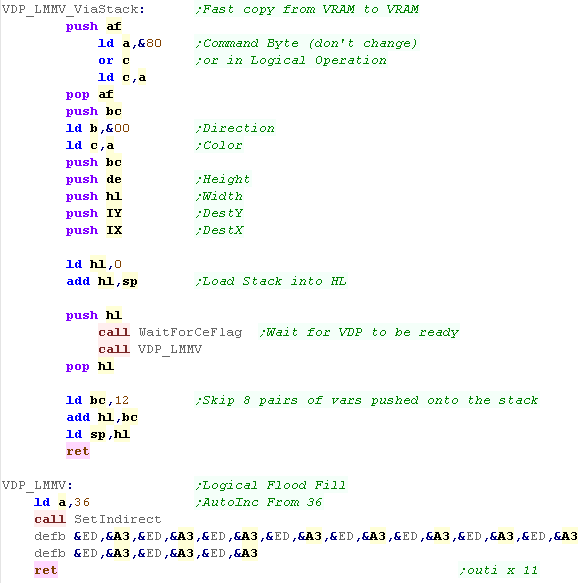
LMMM (Logical move VRAM to VRAM) - Logical Copy (good for transparent
sprites)
We're going to try out every single Logical operation on our
sprite, to see how the pixel data is effected.
We'll draw a strip of 20 pixels, and specify an operation with our
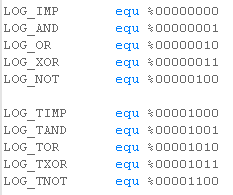
predefined symbols... the operation will be specified in C
The LOG_Txx options use color 0 as a transparent color. |
 |
Pretty much like before, we need to fill registers R32
onwards...
This time however, we need to change the bottom nibble of the
'Command byte' as it's the 'Logical Operation'... we OR in the
value in C to do this |
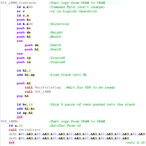 |
The result can be seen below - along
with the Logical operation and it's bits that are set in the low
nibble of the Command byte (Reg 46)
 |
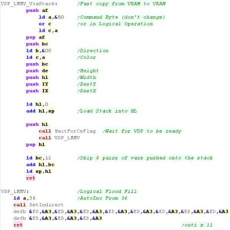
LMMV (Logical move VDP to VRAM) -
Logical Fill
Logical fill is slower than the high speed version, but it can
be used for effects that may be useful.
In this example, we'll fill areas of the screen with the standard
Implicit and XOR options. |
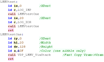 |
| Like the others, we need to set Registers 36 onwards |
 |
| The results will be shown to the screen. |
 |
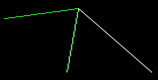
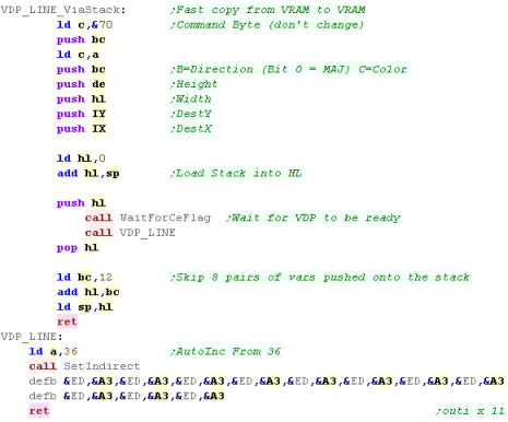
LINE - Draw a line
The VDP can draw lines for us...
The definition is slightly odd...
Usually NX is width - but for this command it's the length of the
Long Side
Usually NY is height - but for this command it's the length of the
Short Side
We specify a Direction as we often do, but in this case Bit 0 is
the 'MAJ' bit... setting this flips the Long side.
We also specify the typical XY position, and a color for the line
|
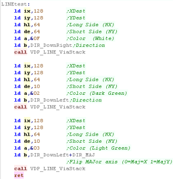 |
We need to set Regsiters 36 onwards...
We also need to set the Color byte, apart from that the rest of
the code is typical. |
 |
| The Three lines will be shown to the screen... The middle one
(light green) is flipped because of the MAJ bit. |
 |
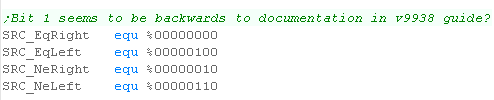
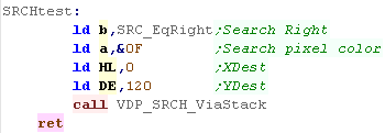
SRCH - Search line for a color
This function may be useful for a graphics package, for example
a fill routine.
It searches the current X line - either Left or Right - for a
color... we can find the color itself, or the first pixel that
isn't the color. |
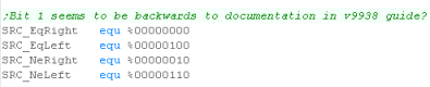
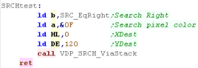 |
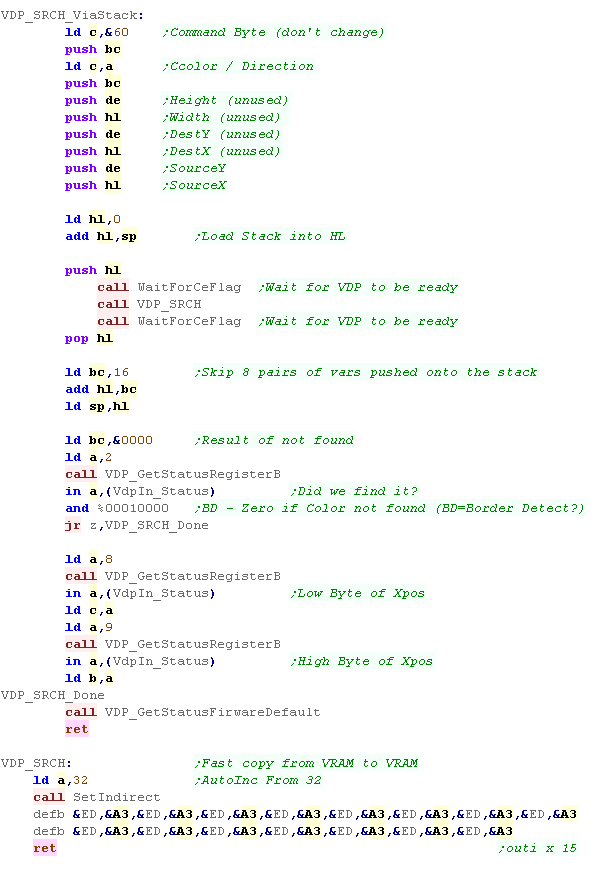
When we want to search, we fill registers 32 onwards as usual.
When the command completes however, we need to do some special
things!
First we need to check the CE flag, to see the command really
finished..
Next we check the BD flag (bit 4) of Status Reg 2 ... if it's 1 we
found the pixel... if it's zero it was never found.
If we wound the pixel, we need to read in the low byte of the Xpos
fro Status Reg 8... and the high byte from Status Reg 9... note
unused bits (9+) are set to 1 |
 |
| In this example we found a pixel at 120 (we placed it there!) |
 |
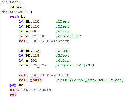
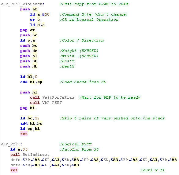
PSET - Set a pixel
We can use PSET to set pixels - we can even use Logical
operations
In this example, we XOR one of the pixels - effectively making it
flash every other draw |
 |
| We transfer our data to Register 36 onwards |
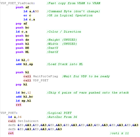 |
| The pixels will be drawn to the screen. |
 |
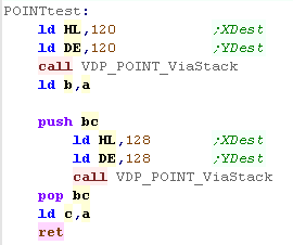
POINT - Read a pixel
We can read a point from the screen, and return the color of
that pixel in A
We're going to define a function that will return the color for
us. |
 |
The basics are the same as any other of our commands which use
registers 32+
Most of the registers actually aren't needed (NX/Y DX/Y)... but
it's easier just to give them dummy data.
Once we've run the command, we read from Status Register
7... it will contain the color of the pixel |
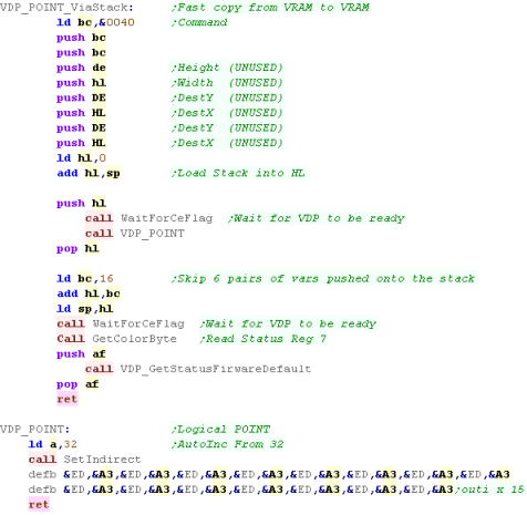 |
Our colors will be read from this screen... in this example one
pixel was color 15, the other color 2 (from the PSET example)
|
 |
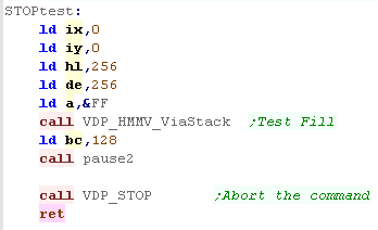
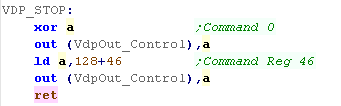
STOP - Abandon ongoing Task
The VDP can only do one job at a time, but we can stop it and
change the job!
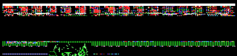
In this test, we'll set the VDP to clear the screen white... wait a
bit, then abort the job! |
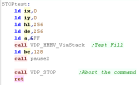 |
| To abort the job, we just send a 0 to the command register R46 |
 |
| The Fill command only managed a few lines before we aborted it! |
 |
Phew! We've looked at all the commands!... The
VDP is pretty powerful, and gives up lots of functionality...
Remember it's a second processor... the Z80 can do other
things while it's drawing, but we'll have to check the CE flag
(and wait if needed) before issuing another command!
|
|
|
|
Command |
HMMC |
YMMM |
HMMM |
HMMV |
LMMC |
LMCM |
LMMM |
LMMV |
LINE |
SRCH |
PSET |
POINT |
STOP |
| Register |
|
Purpose |
Fill Vram From CPU |
Fast Copy (Y axis) |
Fast Copy |
Fill |
Logical Fill Vram
From CPU |
Logical transfer
data to CPU
|
Logical Vram to Vram |
Logical Fill |
Line |
Search (Xaxis) |
Pset |
Read Point |
Stop |
| R32 |
SX-L |
Src X
|
|
|
X |
|
|
X |
X |
|
|
X |
|
X |
|
| R33 |
SX-H |
Src X |
|
|
X |
|
|
X |
X |
|
|
X |
|
X |
|
| R34 |
SY-L |
Src Y |
|
X |
X |
|
|
X |
X |
|
|
X |
|
X |
|
| R35 |
SY-H |
Src Y |
|
X |
X |
|
|
X |
X |
|
|
X |
|
X |
|
| R36 |
DX-L |
Dest X |
X |
X |
X |
X |
X |
|
X |
X |
X |
|
X |
|
|
| R37 |
DX-H |
Dest X |
X |
X |
X |
X |
X |
|
X |
X |
X |
|
X |
|
|
| R38 |
DY-L |
Dest Y |
X |
X |
X |
X |
X |
|
X |
X |
X |
|
X |
|
|
| R39 |
DY-H |
Dest Y |
X |
X |
X |
X |
X |
|
X |
X |
X |
|
X |
|
|
| R40 |
NX-L |
Num X |
X |
|
X |
X |
X |
X |
X |
X |
X |
|
|
|
|
| R41 |
NX-H |
Num X |
X |
|
X |
X |
X |
X |
X |
X |
X |
|
|
|
|
| R42 |
NY-L |
Num Y |
X |
X |
X |
X |
X |
X |
X |
X |
X |
|
|
|
|
| R43 |
NY-H |
Num Y |
X |
X |
X |
X |
X |
X |
X |
X |
X |
|
|
|
|
| R44 |
CLR |
Color |
X (first pixel) |
|
|
X (Color) |
X (Color) |
|
|
X (Color) |
X (Color) |
X (Color) |
X (Color) |
|
|
| R45 |
ARG |
Argument |
X (Direction) |
X (Direction) |
X (Direction) |
X (Direction) |
X (Direction) |
X (Direction) |
X (Direction) |
X (Direction) |
X (Direction) |
X (Direction) |
X (Dest) |
X (Dest) |
|
| R46 |
CMD/ LOP |
Command/
Logical Op (x) |
X (&F0) |
X (&E0) |
X (&D0) |
X (&C0) |
X (&Bx) |
X (&A0) |
X (&9x) |
X (&80) |
X (&70) |
X (&60) |
&(5x) |
&(40) |
&00 |
|
|
|
|
|
|
|
|
|
|
|
|
|
|
|
|
| Readable Registers |
|
|
|
|
|
|
|
S7= Pixel Data |
|
|
|
S2=Status
S8/9 = X |
|
S7=Color |
|