

Learn Multi
platform Z80 Assembly Programming... With
Vampires!
Platform Specific Lessons
Platform Specific Lessons
<- Back to the Main
Contents & Basic Z80 Assembly Lessons
Platform Specific Series - Lets learn how the hardware of the systems work, so we can get it to do what we want... Covers Amsrad CPC,MSX,ZX Spectrum, TI-83,Enterprise 128/64 and Sam Coupe!
Platform Specific Series - Lets learn how the hardware of the systems work, so we can get it to do what we want... Covers Amsrad CPC,MSX,ZX Spectrum, TI-83,Enterprise 128/64 and Sam Coupe!
| The Examples
here will use a height based on 192 pixels tall... this can be
extended to 212 tall by setting bit 7 of Reg R9 |
 |
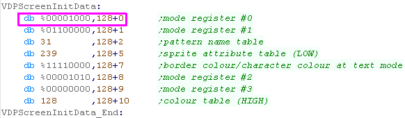
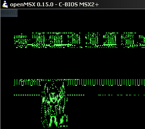
Graphics Mode G5 (32K) - 512x192 4 color
| Want More Resolution?... We can use a 512x192 screen mode - as
it's only 4 color, we won't even use more memory We just need to set the mode bits of R#0 to enable this mode |
 |
||||||||||||||||||
| The screen mode will look slightly squashed!... but we've now got
twice the horizontal resolution Each byte in the screen contains 4 pixels, in linear format:
|
 |
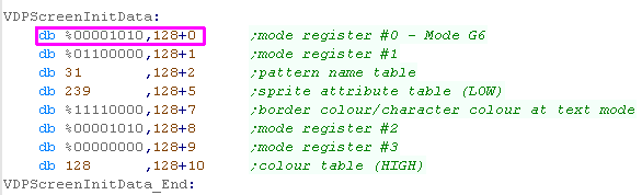
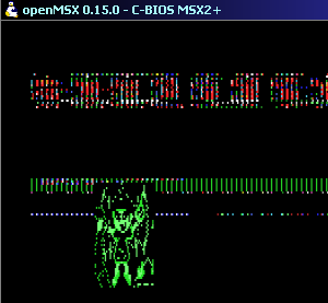
Graphics Mode G6 (64K) - 512x192 16 color
| 4 colors not good enough for you? we can use a 16 color mode - but
we'll take twice as much memory! Again, we just need to set the mode bits of R#0 to enable this mode |
 |
||||||||||||||||||
Each byte in the screen contains 2 pixels, in linear format:
|
 |
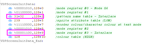
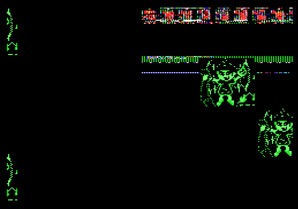
Interlaced Modes... 192 x2= 384 pixel tall screen
| The Bitmap modes can allow for 'Interlacing'... this will use Two
consecutive pages of VRAM for alternate lines of the drawn screen
(Doubling memory requirements) We turn on the IL and EO flags of Reg R9 ... and set bit 6 of Reg R2 (Memory address for the screen) |
 |
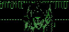
| Alternate screen lines will use Page 0 (Lines 0-255) and Page 1
(Lines 256-511) Because we've only drawn to page 0 (lines 0-255) we've got an interlaced sprite! |
 |
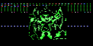
| If we split our sprite into two - one for odd lines, and one for
even lines... Then we draw the sprite twice - Once at our Ypos and Once with the Ypos+256 (Page 1 version) The result will be our same sprite, this time much smaller and more detailed! |
  |
 |
Interlacing
works on all the graphics mode, but it doubles the data
requirement... and using 2 pages are a pain! You're unlikely to want to use it for games... but it might make a nice 'cutscene' screen mode... or if you're developing an office app like a Drawing package, Word processor or Desktop Publishing app. |
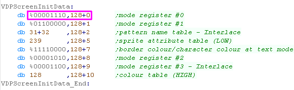
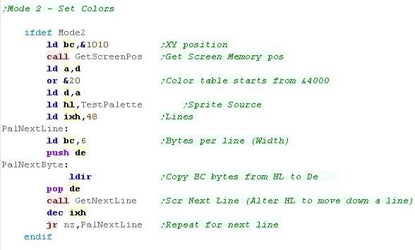
Graphics Mode G7 (64K) - 256x192 - 256 colors... and beyond!
| This is the highest color depth mode... using 64k per screen
(though it can be interlaced - using all 128k vram) We need to set Mode Register R0 to %00001110 to set mode G7 |
 |
||||||||||||||||||
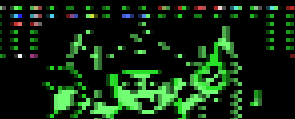
| 256 color mode works differently to other modes... it does not use
a palette!... Each byte defines a pixels' RGB value in the following linear format:
|
 |
 |
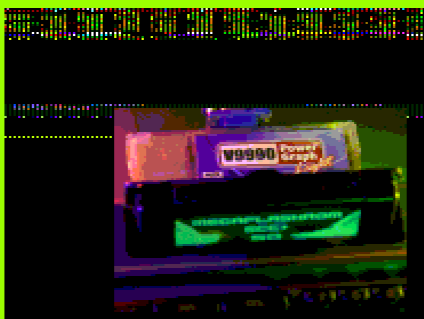
MSX2 256 color mode uses the same palette as the Enterprise 128!... it gives a good range of colors - the most for the MSX2 - but the huge 64k page size is going to be slow to fill... |
MSX2+ Graphics Mode G7 + YJK (64K) - 256x192 - 19268 Colors!
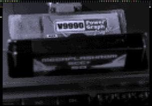
| With he MSX2+ a new 'mode' was added... YJK... turning this on
alters the way mode G7 works... But how can G7 output 19268 colors without using any more memory? Well the colors are 'encoded' in two parts... 1. A per pixel 5 bit Greyscale shade (Y) 2. Two Encoded Color values (6 bit each) that are shared between 4 horizontal pixels (J+K) The result... each pixel can be a different brightness - but will be the same color... this may sound like it will look bad- but Codecs like JPEG and MPEG do this all the time. |
1. 2. 2.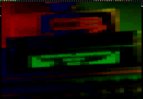 |
|||||||||||||||||||||||||||||||||||||||||||||||||||
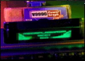
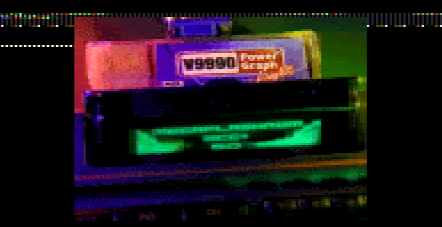
| The resulting image can be seen to the right!... But beware! Due
to the format, our image color will corrupt if we don't put it on
a pixel dividable by 4, eg (x=0,4,8 etc) Four consecutive Pixels have the following buildup:
The 6 bits of K and J parts are split into a High and Low part... KL is stored in bits 0-2 of Pixel 1... KH is in bits 0-2 of pixel 2... JL and JH are stored in the same bits of Pixel 3 and 4 |
 |
|||||||||||||||||||||||||||||||||||||||||||||||||||
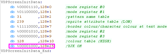
| We need to set Screen mode G7 as before, but also set MSX2+
register R25.... We need to set bit 3 of R25 to 1 to turn on YKJ |
 |
|||||||||||||||||||||||||||||||||||||||||||||||||||
| The Formula to calculate YKJ from RGB is as follows: Y = (B/2) + (R/4) + (G/8) K = (G-Y) J = (R-Y) (K and J are signed - they can be negative!) To reverse the procedure: R= Y+J G= Y+K B= (5/4)*Y - (J/2) - (K/4) |
The code below is used in AkuSprite Editor to produce YKJ Values Take the top 5bits of the resulting Y and 6 bits of JK to produce the bytes for the sprite file 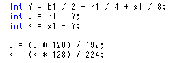 |
| YJK mode
offers even more colors than 256 color mode... but as it uses 4
consecutive pixels - 'Pixel' alignment will be impossible... and
drawing fonts and the like may be ugly in color... There is a solution though... Almost all the colors of YJK - with a standard 16 color palette to boot!... YJK with 'Attributes' (palette) - YJKA! |
 |
MSX2+ Graphics Mode G7 + YJK + YAE
Attributes (64K) - 256x192 - 12499 YJK Colors + 16 Palette Colors !
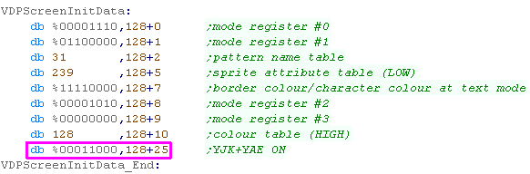
| There will be times that YJK may not work... it would be nice to
have a few 'regular' palatalized colors to use for text or sprites
in addition to the thousands of 'true colors' This is what 'YAE' does... The Y component is reduced from 5 bits to 4 (J & K are unchanged)... when this spare bit (bit 3) is set to 1 the top 4 bits define a palatalized color number... Pretty much the best of both worlds! We just need to set bit 4 of R25 to 1 for YAE... (in addition to bit 3 for YJK) |
 |
|||||||||||||||||||||||||||||||||||||||||||||||||||||||||||||||||||||||||||||||||
Bit 3 will be 0 for YAE (Y component is reduced to a still
decent 4 bits)... when it's 1 the 4 Y bits become the Color
number.
|
 |
|||||||||||||||||||||||||||||||||||||||||||||||||||||||||||||||||||||||||||||||||
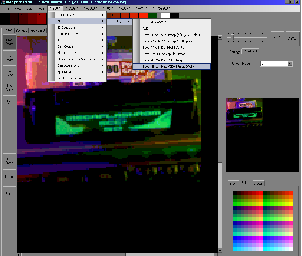
| Want to create Files for these modes? My Free Open Source AkuSprite Editor can export files for all these modes (it was used to create the sample files) It supports the native MSX2 G7 RRRGGGBB color palette... and can export YJK Files* *Note - although AkuSprite Editor can export JYK files - it is only a 256 color editor... The sample file was converted to 256 colors using Irfanview, and the optimized palette imported into AkuSprite (... this allowed a file to be created with better colors than the standard G7 mode... but AkuSprite cannot create a file with the full 12k/19k colors... It would be a large amount of work to make the editor support true color, and it's not what the tool was intended for, so it's not expected that this will change. |
 |


Todays Registers!
We're going to use the following registers
today!
| Section |
Addr |
Name | Bits | Bit Meaning |
| LCD | FF40 | LCDC - LCD Control (R/W) | DwWBbOoC | O=Object sprite size 1=8x16 / D=Disable Screen / w=window at (&9C00/9800) W=Window on / b=background at (&9C00/9800) / B= Back on |
| LCD | FF41 | STAT - LCDC Status (R/W) | -LOVHCMM | Ly coincidence interrupt on, Oam Interrupt on, Vblank interrupt on, Hblank interrupt on, Coincidence flag, MM=video mode (0/1 =Vram available) |
| Tile | FF42 | SCY � Tile Scroll Y | YYYYYYYY | 0-255 |
| Tile | FF43 | SCX � Tile Scroll X | XXXXXXXX | 0-255 |
| LCD | FF45 | LYC - LY Compare (R/W) | LLLLLLLL |
L=Line
LcdStat Interrupt occurs |
| Tile | FF4A | WY - Window Y Position (R/W) | YYYYYYYY | Y Pos 0-143 (0=Topmost visible pixel) |
| Tile | FF4B | WX- Window X Position minus 7 (R/W) | XXXXXXXX | X Pos 0-166 (7=Leftmost Visible pixel) |
| INT | FFFF | IE - Interrupt Enable (R/W) | ---JSTLV | J=Joypad S=Serial T=Timer L=Lcd stat V=vblank |
The Window
| The 'Window' is always attached to the bottom right of the
screen... We can set a Width and Height of the window, and this can make it cover the corner... the whole right hand side, the bottom, or even the whole screen. The Window uses the same Tile patterns as the regular tilemap... The main purpose of the tilemap is for onscreen Stats - such as lives/score or an inventory... as it doesn't scroll with the regular tilemap (It can't scroll at all) |
  |
| Enabling the window is done with bit 5 of &FF40.... we just
set it to 1 We don't want the Window to use the same Tile Data as the regular screen (otherwise what's the point?!)... so we need to set it to Tilemap 2 at &9C00... we do this by setting bit 6 of &FF40 |
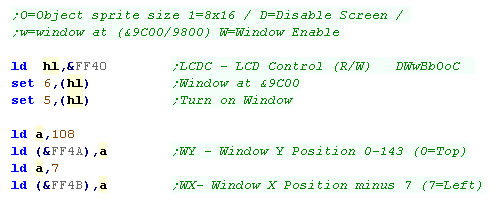 |
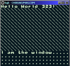
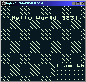
| This example will set the Window to the bottom of the screen...
perfect for our Score, Lives and any item display! |
|
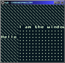
| We can't scroll the Window, but we can scroll the Tilemap... we
do this with registers &FF42 and &FF43 |
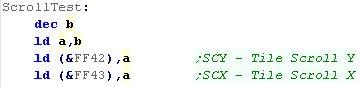 |
| We can scroll the Tilemap at the pixel level! We can also move the window at the pixel level, but it's always stuck at the bottom right - and tiles cannot be transparent. |
|
| Technically
We can't move the Window from the bottom right... but we can
'Trick it' into doing something else... Say we get the tilemap to cover the whole right half of the screen... but we turn the window off half way down the screen while it's redrawing... The window would only appear covering the top right corner! How do we do that? With an Interrupt!... And we'll learn about them next! |
|
Interrupts and Alternate Tile Pattern
Address
| The GB Screen is 160x144 (20x18 Tiles)... this is a total of 360
tiles!... since the GB classic is only capable of 256 tiles, we
can't show a complex image which would cover the entire screen
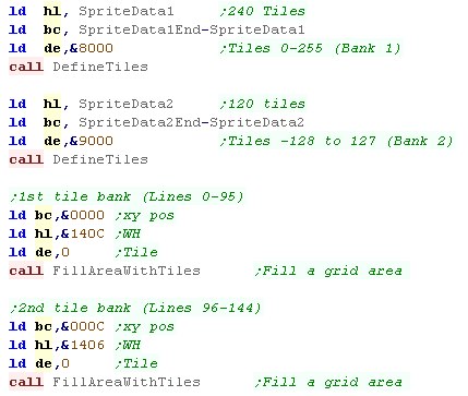
with non repeating graphics... BUT... the Tile Patterns can be stored at two different addresses &8000-8FFF or &8800-97FF.... these two overlap, but they do allow for an extra 128 tiles... giving us 384 tiles! By switching the To the &8000-8FFF at the top of the screen, and &8800-97FF at line 96... we can use both addresses to cover the entire screen! Rather strangely the Patterns at &8800-97FF are numbered -128 to 127... with tile 0 at &9000 |
 |
| We've spilt our image into two parts... the first
2/3rds are in SpriteData1.... the second
1/3rd is in SpriteData2 We load in our data into the 2 banks with the DefineTiles function we used before... We use our previous FillAreaWithTiles function to fill the two areas of the screen with tiles 0-240 for the first 2/3rds and tiles 0-120 for the second 1/3rd |
 |
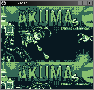
| We've filled the screen with tiles... but the bottom 1/3rd shows
the same as the top 1/3rd We need to use Interrupts to switch the Tile Pattern Address during the screen redraw (at line 96) to get our full image! |
|
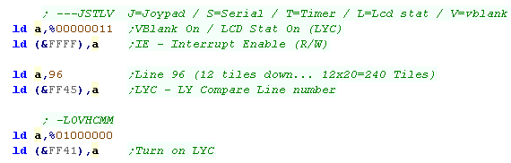
| We need to turn on two interrupts... VBLANK - which occurs at
the start of the screen (line 0)... and LYC - which occurs at a
line of our choosing... LYC is part of the LCD-STAT interrupt... we turn VBLANK and LCD-STAT on with &FFFF bit 0+1 We next select the line we want the LYC interrupt to occur... we do this with &FF45 Now we enable LYC with &FF41 bit 6 |
 |
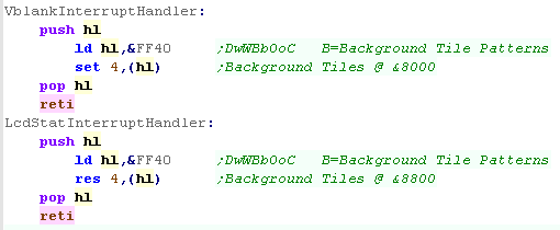
| We need to put jumps in our header to jump to the functions which will handle the events , and change the Tile patterns | 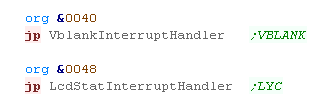 |
| We need to control bit 4 of &FF40... We need to turn it on
during Vblank (Line 0) to set the first Tile Pattern address We need to turn it off during LCD-STAT (LYC) (Line 96) to set the second Tile Pattern address |
 |
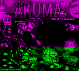
| The result will be our full-screen Title image - every tile on the screen is different! | 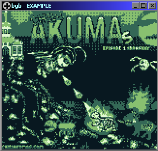 |
| All
we've done here is switch the tilemap once during the redraw...
But there are far cleverer things we could do! For example, we could move the tilemap during the redraw - making the screen 'ripple' in a wave... or we could move the tilemap in two parts, to have a splitscreen effect! It all depends how creative you are... and how much debugging you're willing to do! |
 |
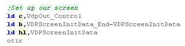
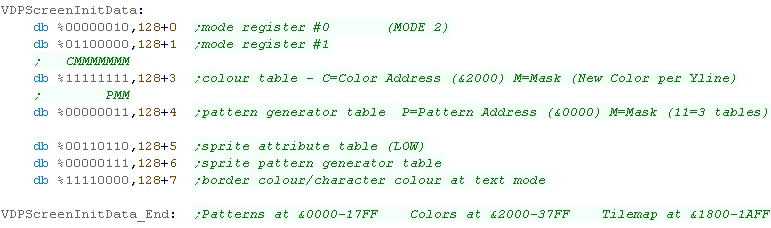
MSX1 8x1 Color
The MSX 1 screen is made up of Black and
white patterns, and Color data - each uses 8 bytes per tile
Black And White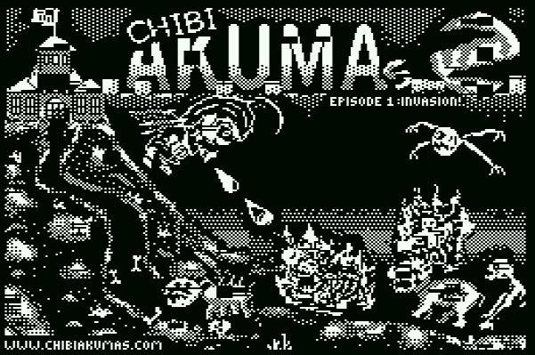 |
Color  |
The Two Combined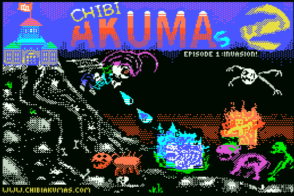 |
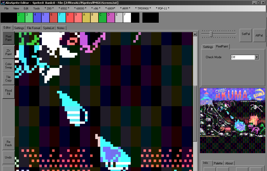
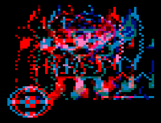
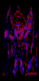
| We're going to use a screen based on the Spectrum... but the
MSX1 can do better! Take a look at the fireball in the preview to the right. Each 8x1 line on the MSX1 can have a different foreground and background color. The fireball has a black background, but alternating lines are White or Cyan... The ZX Spectrum couldn't do this... the color around the eye is also improved thanks to the MSX! |
 |
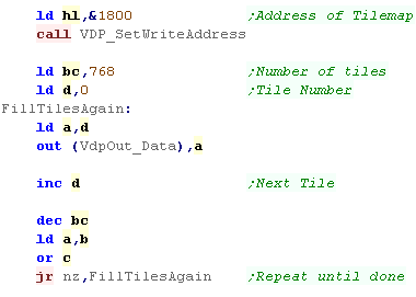
| Our 256x192 screen would need 768 tiles to cover it... but in
the 'normal' mode we only have 256... This would mean our image would repeat 3 times. |
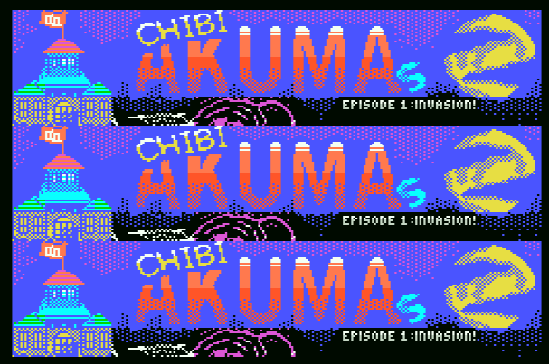 |
| By changing the settings of the screen registers - each 1/3rd
will use a different 256 tiles - allowing us to show a full color
screen! Very nice! |
|
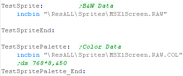
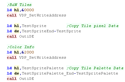
| The latest version of AkuSprite Editor can Export MSX1 files - it will split the data into 2 parts... RAW will contain the bitmap data and .COL will contain the matching colors | 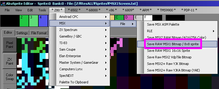 |
|
Beware! Akusprite editor
will 'Convert' the 16 color image to MSX1 format - but if you've
made a mistake and used 3 colors in the same 8x1 area one will be
lost! Use the 'MSX1 8x1 Color' Display mode to check your image looks OK! |
The Code
|
Splitting the
screen into 3 tilemaps gives 3x the tile count - but it will
cause your font problems! If the bottom 3rd is your status screen you'll be fine, but if you need to show text in all areas, you'll have to define your font in all 3 tilemaps... in all 3 tilemaps, Our 96 character font would use up 288 tiles total... leaving only 480 left! |

Amstrad CPC Screen Modes
| The Amstrad modes all work differently, and depending on the
screen mode, we're going to need to move the bits of each pixel to
shift each pixel in the byte to the 'Visually' opposite side of
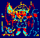
byte We're going to use the sprite below for our flipping tests (Shown un-flipped) 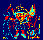 |
|
| We're only
looking at H-flipping the sprite in today's example, V-flipping
is pretty easy, we just read in the lines of the sprite
backwards, or move up the screen as we draw instead of down. Because there are multiple pixels in a byte, it's more tricky doing the Horizontal flip, so that's what we'll look at today. |
|
Macros to flip the image
| We're going to create macros to convert each screen mode. these
will convert a byte in A - and we can use them for either direct
drawing to the screen, or building a lookup table. Mode 2: In mode 2 each pixel is a bit... We need to shift each bit to the opposite side of the byte by bit-shifting. As it's black and white, This function will also work on the ZX Spectrum! |
 |
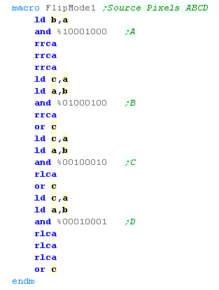
Mode 1: In mode 1 each pixel is two bits, one in the top nibble, and one in the bottom... there are 4 pixels per byte. We need to shift each pair of bits for each of the 4 pixels |
 |
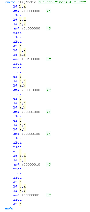
Mode 0: In mode 0 each pixel is four bits, the bits are in odd, or even bit positions for each of the two pixels in the byte. We need to shift all four bits of the pixels into the opposite position. |
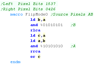 |
Drawing the Sprite
| If we want to show a Mode 1 sprite, we essentially do almost the
same as before (in the Simple series Bitmap example) However this time we use the 'FlipMode1' macro to reverse the byte before showing it to the screen, we also DEC HL to move to the Left on the screen (rather than right in the previous example) |
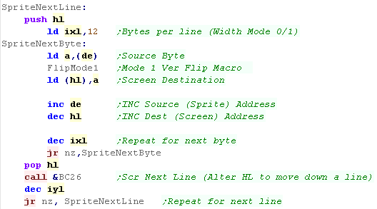 |
| This will show the flipped sprite to the screen. The same procedure also works with Mode 2 or Mode 0. |
 |
Using a Lookup Table to speed things up
| Recalculating the sprite in
real time in this way is OK, but it's a bit slow... alternately we
can define 256 bytes of data in a LookUp Table, and 'Preflip'
every possible byte, this will allow us to easily read from the
lookup table to get the 'flipped' byte almost instantly. The table needs to be aligned to a byte boundary (starting at &xx00 - eg &1800 or &1900) |
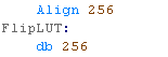 |
| To fill our LUT, we need to use the low byte (L) as a source for
our macros (either FlipMode0,FlipMode1 or FlipMode2) We need to fill in the 256 possible source bytes into this LUT. |
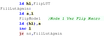 |
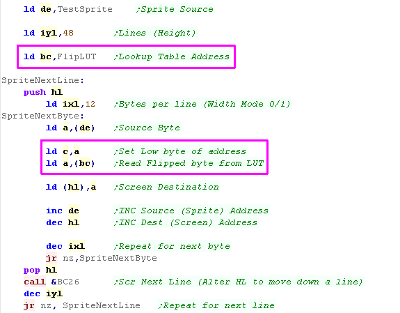
| We're going to use BC for the address of our Lookuptable. When we want to 'Flip' a byte from our sprite, we just set C to that byte, and read in from the address (BC) Because we've pre-calculated the flipped bytes, we'll read in the flipped equivalent of the byte in C We now just write that to the screen... much faster than using the macro for each byte! |
 |
| The look up
table will almost certainly be better than storing copies of
sprites that are pre-flipped, but whether it saves memory over
the 'realtime macro' option will depend on complex your sprite
drawing routines are. In this version, the sprite routines are short and simple, but if you're got heavily optimized ones with unwrapped loops, then the LUT could actually save memory! |
|
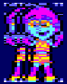
Example 1 - No Transparency
| We're going to look at Mode
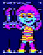
0 in this example... and we're going to use as sprite of 'Chibi
Alien Yarita' - as it's a nice colorful sprite which allows for
clear transparency We're going to draw 3 copies of the sprite over themselves - and see how the transparency occurs (or doesn't in this example!) To the right you can see the 'PSET' example, the first two draws of the sprite have been erased by the third draw - this is because we have 'no transparency'! |
 |
Example 2 - Byte Zero Transparency
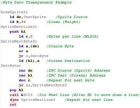
| 'Byte Zero' Transparency is super easy... when all the pixels in
a byte are color zero (IE when the byte value =0) then we simply
don't draw the byte!, we just skip over the draw with a JR command This is a fast and easy way of achieving simple transparency with just an extra command or two! |
 |
| The sprite will be shown... Notice the 'chunky' border around
the legs... when one pixel is Black (Color 1) and the other is
Color 0 (Dark Blue) - both are shown. This is because there are two pixels per byte - and both need to be Color 0 for the byte to be transparent. |
 |
| This
was the kind of transparency used by ChibiAkumas - it's pretty
fast, and works well when the background is mostly color 0
anyway.. It has a tendency to give the characters a 'Black' (or whatever Color 0 is) border - but that's not so bad with cartoon graphics. |
|
Example 3 - Color Zero Transparency (Via Lookup Table)
| The simple example was a bit
limited, we really want every pixel to be able to be transparent,
but this is complex to calculate. We're going to need a lookup table - which will store the masks to remove the background when we want to draw our sprite. The LookUp Table will contain 256 entries, one per possible screen byte. it needs to be aligned to the byte boundary &xx00 - starting at something like &1700 or &1800 |
 |
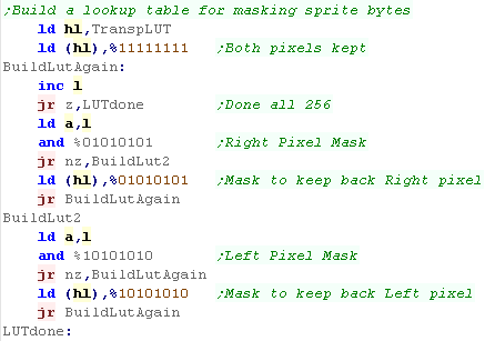
| We need to fill the lookup table... the lookup table will
contain values we'll AND with the background... removing the bits
as needed so we can OR in the final sprite. The two pixels of the Mode 0 screen use 4 bits each.. Bits 0,4,2,6 are the right pixel, and bits 1,5,3,7 are the left pixel... We want to check if all the bits of a pixel are zero, and if any of them are, we want to retain the background by setting the pixels bits to 0, otherwise they will be 1 |
 |
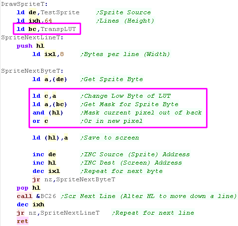
| We don't need to change much of our previous example... We now load BC with the address of the LookUp Table. When we read in a sprite byte, we load it into C. As our Lookup table is aligned, and contains all the masks for the sprite bytes, we now load our mask in from (BC) and AND it with the current screen byte in (HL) Finally we OR our sprite byte over the top (Still in C) |
 |
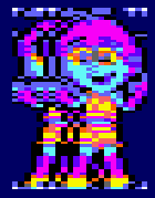
| The result can be seen... effectively 'perfect' Color Zero
transparency! It doesn't cost much time, but it does cost 256 bytes for the Lookup Table. |
 |
|
This method of
transparency is used by many fast CPC games (Such as Operation
Wolf)... it works great for 16 color mode, provided you can spare
the extra ram for the LookUp Table... Note: Operation Wolf actually uses 'Stack Misuse'... using the stack pointer to read bitmap data fast! |
Example 4 - Sprite + Mask bitmaps
| LUT transparency is probably best for 16 color mode... but in 4
color mode, losing one of our 4 colors is a pain.. if our
background is black, we may want a black border around our
characters. We'll a good solution is a Mask Sprite... the concept is the same as the LUT option, but we have two sprites, one that masks out the background, and one that is the actual color sprite. |
|
|||
| We now have two bitmap files, one for the Sprite color, and one for the Mask. | 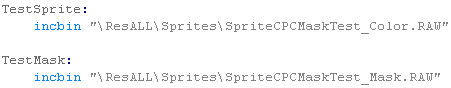 |
|||
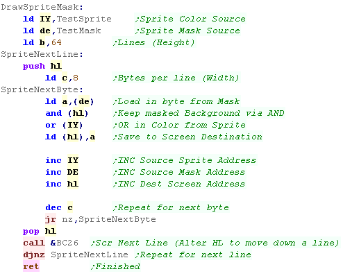
| Our sprite routine is a little different.... we're using 3 data
pointers now... DE for the Mask data, IY for the sprite data, and
HL for the screen destination. We load registers with the two sprite files, and AND the mask and background together... before ORing in the color information. We then INC all 3 pointers. |
 |
|||
| The Sprite will have a Color 0 border - but the masked parts will show through to the background. | 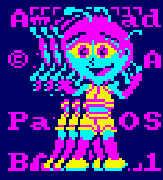 |


|
AkuSprite
Editor now has a new display mode 'Transparency Mask' will ONLY
show color 16 (the transparent color) - all other colors will be
black. This was used to export the transparent example in today's lesson... but it's not been tested much, so it may need some more work! |

| This tutorial
has been tested on Fusion 3.64 which emulates the lightgun - if
you're using an earlier version - or a different emulator, it
may not support the lightgun. |
|
The Theory of the SMS LightGun
| The SMS LightGun is super precise, but it's hardware is very
simple... The lightgun returns just two binary bits of data... one is the fire button... the other is the detection of light... To actually read in the 'shot' screen position we have to follow a procedure during the interrupt handler... 1. Test the fire button - if it's not pressed, give up 2. Flash the screen (All colors to white) 3. Read the light sensor until it detects the white flash - when it does, the lightgun is pointing to the pixel the CRT beam just drew 4. Read the Horizontal and Vertical Position from the hardware registers |
 |
Interrupt Handler
| Because we're going to run before the screen draws during
Vblank, We're going to have to use the Interrupt handler... This
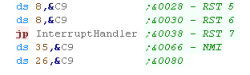
requires a few things 1. We need to declare an interrupt handler jump at &0038 |
 |
| 2. We need to flip to the shadow registers at the start of the interrupt handler (We're relying on our main code not changing these) | 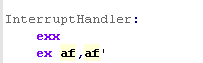 |
| 3. We need to read in from vdpControl on port &BF to clear the interrupts, flip back from the shadow registers, turn interrupts on and return. | 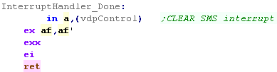 |
Detecting the Lightgun Fire pos
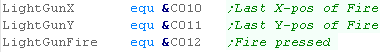
| We're going to declare 3 variables in RAM 1. A 'fire' flag - if the fire button was pressed. 2. The X position of the light gun when the fire button was pressed. 3. The Y position of the light gun when the fire button was pressed. |
 |
| OK, lets start our interrupt handler... First we
set up the VDP to receive a new palette, If the Fire is pressed - we'll flash the screen white, if not we'll reset the palette to the normal colors. Next we'll test the fire button (bit 4) of port 1 (or Bit 2 of port &DD for Port 2) |
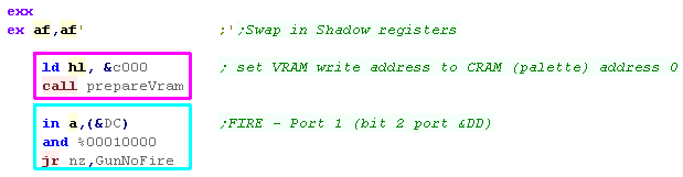 |
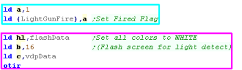
| Let's set our 'Fire flag' to 1, Next we'll send a 'flash palette' to the palette registers - this is just setting all the colors to white. |
 |
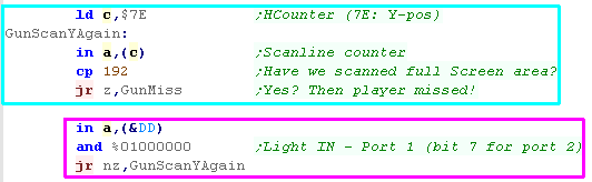
| As the screen draws, the Y line number of the currently drawing
line (HCounter) can be read from port &7E... We just set the screen to white, so at some point the light sensor will detect it - if the lightgun is on port 1 we test the light sensor with bit 6 of port &DD If the H-counter on port &7E reaches line 192 before the sensor sees light, then we missed the screen! |
 |
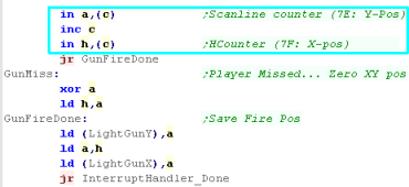
| If the fire was detected, we need to read in
the Y-pos from port &7E... and X-pos from &7F Otherwise we'll set them both to zero |
 |
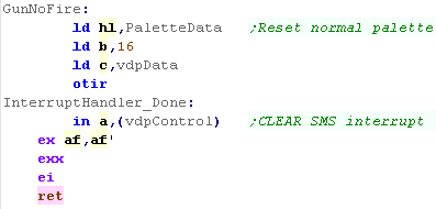
| If fire wasn't pressed, We need to reset the normal palette Whatever happened, we need to read in from the VdpControl port (&BF) - otherwise the Interrupt will keep firing forever locking our program!... then we return |
 |
Testing our program
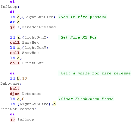
| We need a little test program! We'll wait until the Fire flag is set, and then show the X,Y pos to the screen. |
 |
| Here are the results! The first value is the X-position The second value is the Y-position |
Test 1: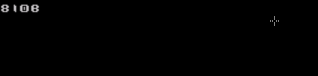 Test 2: 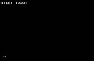 |
| The
MouseClicks don't quite seem to match the Y-position returned -
the Clicck seems to be 8 lines lower than the actual screen
position and returned value, so the top line cannot be clicked
upon, and you can successfully click 8 lines below the last line
of the 'flashing screen' This may be a limitation of the SMS, or an emulator bug - but the same happens on 'Operation Wolf' on the SMS - so it doesn't seem to be a bug in this tutorial. |
|
Calculating Byte Position and Bit Mask
| Because of the layout of the CPC screen, there are multiple
pixels per byte... In screen mode 1 there are 4 pixels per byte,
in screen mode 0 there are 2 We're going to define a function that takes a Xpos from 0-320 in registers AB , and Ypos from 0-200 in C We'll need to calculate the byte position of our pixel we do this by 1 bitshift (in mode 0) or 2 bitshifts (in Mode 0)... we can then use our previous GetScreenPos to get the HL destination We also need a 'MASK' - we'll need the mask to remove the pixel we want to plot from the background - and then plot the new colored pixel.... we read this from a lookup table |
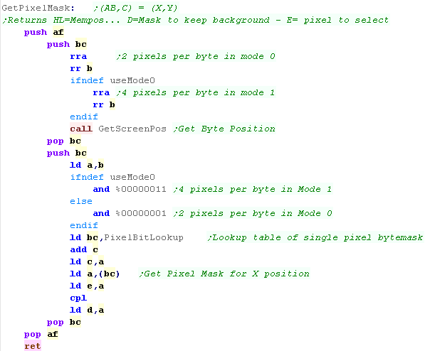 |
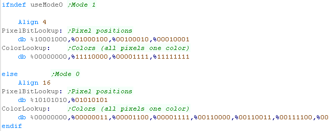
| The Mask lookup table needs to define the pixel positions for
each pixel in the byte. Of course This is very different depending on screen mode! |
 |
| If we want to set a pixel to a color, as well as the pixel mask, we'll need the 'color mask' - defined in this code as a byte in which all the pixels are colored with the color we want, combining the two will yield a colored pixel in the position we want - we'll use this for setting pixels. | 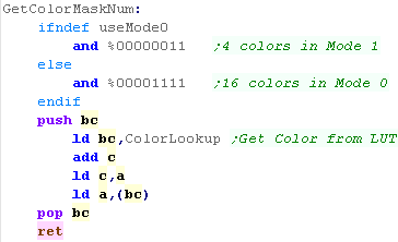 |
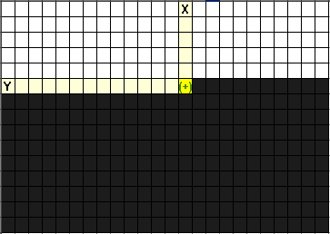
| We're going to draw a 32 pixel diagonal line... We use Get Pixel Mask to convert (X,Y) pos (AB,C) into a HL byte address... a D mask to keep the background and an E mask for the pixel... We use GetColorMaskNum to get a 'color mask (a byte where all the pixels are the selected color) - ANDing this with E, and ORing in the background will set our pixel as required |
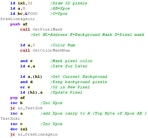 |
| We've drawn our line! |  |
| Drawing
a line in this way is pretty slow, and won't be much use for
gaming. You're going to want to use sprite and byte based
graphics most of the time, However these routines may be handy for slower things - like drawing the UI at the start of a program, or simple effects during a demo. |
|
Copying and flipping pixels
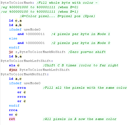
| Of course there's no limit to what we draw! Instead of a line, lets copy an area of our screen pixel by pixel - but lets draw it in reverse! We'll read a pixel from the screen in the XY pos in IX... and plot it to XY pos IY... We'll need to convert the pixels - we could shift the bits, but instead we'll write a generic routine to convert a pixel to a 'color mask'... this will be called ByteToColorMask |
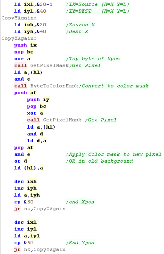 |
| We're going to take a screen byte, and it's pixel position and
convert it to a color mask we do this by shifting it to the rightmost pixel, then shifting left and ORing - effectively filling all the colors with the one specified in B |
 |
| We've copied and flipped a range of our screen pixel by pixel. |  |
|
We've written
some routines to work with pixels... of course, the firmware has
built in pixel routines that you can use, but it's more
interesting to write our own |
| We're going
to use the DEGA emulator to simulate 3D glasses... these use
Red/Cyan 3D 'anaglyph' glasses to achieve 3D - we'll do the same
in this tutorial... so dig out your old copy of Jaws 3D or
Freddy's Dead - stick on those 3D glasses, and get ready to
party in 3D like it's 1989! Of course in actuality the 3D on the SMS was in full color, so we're having to computerize - damn modern TFT's! |
 |
The 3D Theory
| Human beings have two eyes (in case you
hadn't noticed) - they're spaced apart, and get two slightly
different images - our brain is clever and coverts these into 3D
'Depth'... By providing 2 different images to the eyes we can make a flat screen look like it has 'Depth'... Anaglyph glasses use Red/Cyan filters - Red cannot get through the blue filter... and Blue cannot get through the red filter - allowing us to display 2 different images to the 2 eyes - the brain will see this as 3d. Shutterglasses do this differently, blanking out alternate eyes, and showing a different image alternate frames - a 60hz TV will show 30 hz to each eye with Shutterglasses - we need out code to move all the objects alternating frames for each eye. |
 RED - LEFT EYE IMAGE BLUE - RIGHT EYE IMAGE |
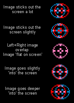
| Depending on the relative position of an
object when it's presented to the left and right eyes we can alter
the '3D ness' of the object. If it's position is the same to the left and right eyes it will appear 'flat' If the right eye image is on the right of the left eye image it will go 'into' the screen If the right eye image is on the left of the left eye image it will come 'out of' the screen. Bear in mind, the size of the screen makes a difference, one CM of separation on your hand held could be 30 CM on your big screen TV! If an object sticks out too far, you may be unable to focus on it - or it may stick out further than the viewer - that's why you may get a headache if you're on the front row of a 3d cinema! |
 |
Controlling the Shutterglasses with port
&FFF8
| Writing to address $FFF8 will send data to
the shutterglasses - it's also stored into the Ram mirror...
Bit 0 of this address will select the eye of the shutterglasses that is shown (the other will be black)... 0 will enable the Right Eye... 1 will enable the Left Eye We can't read back from the Shutterglasses, but we can read from the ram mirror, so reading back from $FFF8 will work fine! |
$FFF8 = Shutter glasses port |
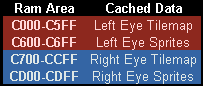
| We need to change the positions of objects
every frame... alternating between the Left and Right eye images To do this we'll 'Cache' all the data for the Tilemap and sprites in ram - we'll store two copies of this data, one for the left eye, and one for the right During the interrupt handler, we'll use $FFF8 to alternate the eye that can see the screen, then push all the data for the sprites and tilemap into VRAM We're going to modify our previous Sprite (SetHardwareSprite) and Tilemap (FillAreaWithTiles) Functions to write to this cache |
 |
Writing routines to write to our cache
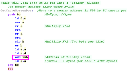
| We need to change GetScreenPos... before it
selected a VRAM address - now it selects a memory address within
the Cache We'll return the address in DE - this version will use a Cache address in IXH - &C0 for the Left eye, &C7 for the right eye |
 |
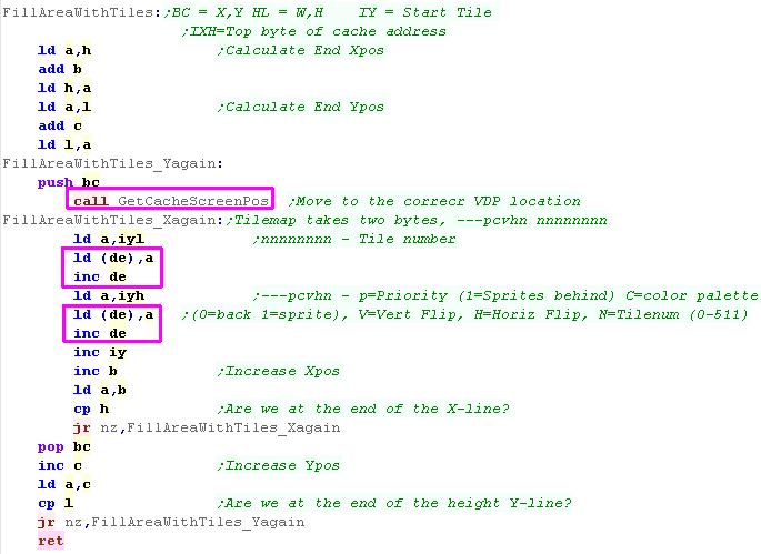
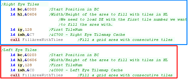
| FillAreaWithTiles will set an area of the
tilemap to consecutive tiles - we use it to draw our Chibiko
Character We need to change the routine to use the GetCacheScreenPos we just wrote, and replace the OUT commands to writes to address (DE) as DE is now used for address writes, we're using IY as our tile number |
 |
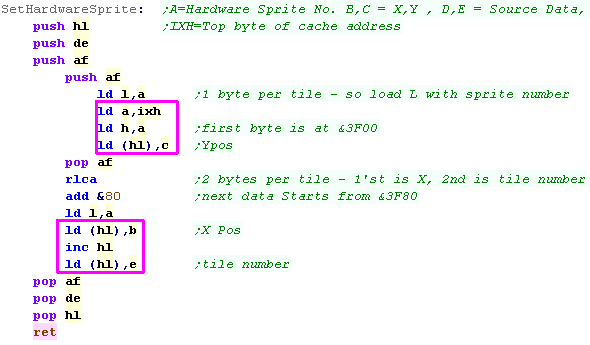
| Our hardware sprite routine also needs to
change - it too needs to write to the cache. We'll use IXH as the address of the sprite cache - &C6 for Left Eye , &CD for Right Eye |
 |
Drawing Our Screen
| We want to draw our Chibiko character We need to do this twice... once for the RIGHT EYE, and once for the LEFT EYE if we want the image to have 3D depth, we need to change the X position of the draw between the two eyes |
 |
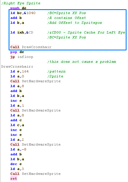
| We also need to draw the sprite twice, the LEFT EYE image will be static The RIGHT EYE sprite will move, making it zoom in and out of the screen in 3D |
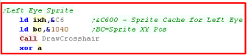  |
| The Chibiko Tiles will appear 'going in' the
screen The Cross-hair sprite will go into and out of the screen |
 |
| We make
things 3D by having a 'difference' in the X position of pixels
in the Left and Right Images - in this example we made the Tiles
appear 'in' the screen by moving them one tile to the right -
this is possibly a bit unsubtle, but without drawing the image
twice, and storing different tile versions (Eating up memory)
there's not much we can do... You'll want to design your graphics and game to work well in 3D and take advantage of the technical capabilities and limitations. |
|

Screen Modes overview
| Mode 4 is a 16 color mode... each pixel has
4 bits - so the top nibble of a byte is the left hand pixel, and
the bottom nibble is the right hand - these define the color used
by the pixel from the normal 16 color palette, Lines on the screen
are consecutive, so we add 128 bytes to move down the screen. Mode 3 is a 4 color mode... each pixel has 2 bits - so the two bits of a byte is the left hand pixel, and each other 2 bit pair is a consecutive pixel - these define the color used by the pixel from the normal 16 color palette Mode 2 is odd!... each pixel is 1 bit, so a byte has 8 pixels of data - but this just defines whether the color is the foreground color or background... the Foreground/Background colors are in a separate Color map... Lines are 32 bytes apart... the main screen is 6k in size, but there is a 2k gap before the color map, which is also 6k... The color map mimics spectrum format, with Flashing bit, Bright Bit, 3 back color bits and 3 fore color bits Bright colors are Colors 8-15 in the Sam palette, color 0-7 are the regular colors. Mode 1 is identical to the spectrum... each pixel is 1 bit, so a byte has 8 pixels of data - but this just defines whether the color is the foreground color or background... each 8x8 square has a Foreground/Background color in a separate Colormap... the main screen is 6k in size, the colormap is 768 bytes just like the spectrum... the screen layout is odd, the screen is split into thirds, and 8 consecutive bytes go down the screen.... see the spectrum tutorial for full details. |
Pixel Data: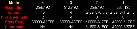 Memory addresses assume Video ram mapped to &0000-&8000 range Mode 1/2 Color data: 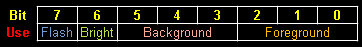 |
Each screen-mode will need the correct format
pixel data, but we can create the correct data with AkuSprite Editor. Lets
draw our 48x48 mascot on each screen mode.
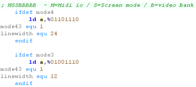
Using Modes 4/3
| Screen modes 3 and 4 are almost the same, we just have a
different byte width... We'll load the screen initialization byte into A... we'll need it in a moment! |
 |
||||
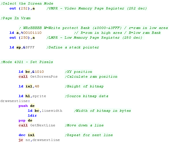
| We need to select the screen mode using port 252 - 2 bits select
mode 1,2,3,4... then we page in the bank of memory with port 250 we'll use 'GetScreenPos' to caclulate the screen address, and 'GetNextLine' to move the address These will copy data from our 'sprite' label into the screen memory. *** This section is used for screen modes 1+2 as well *** |
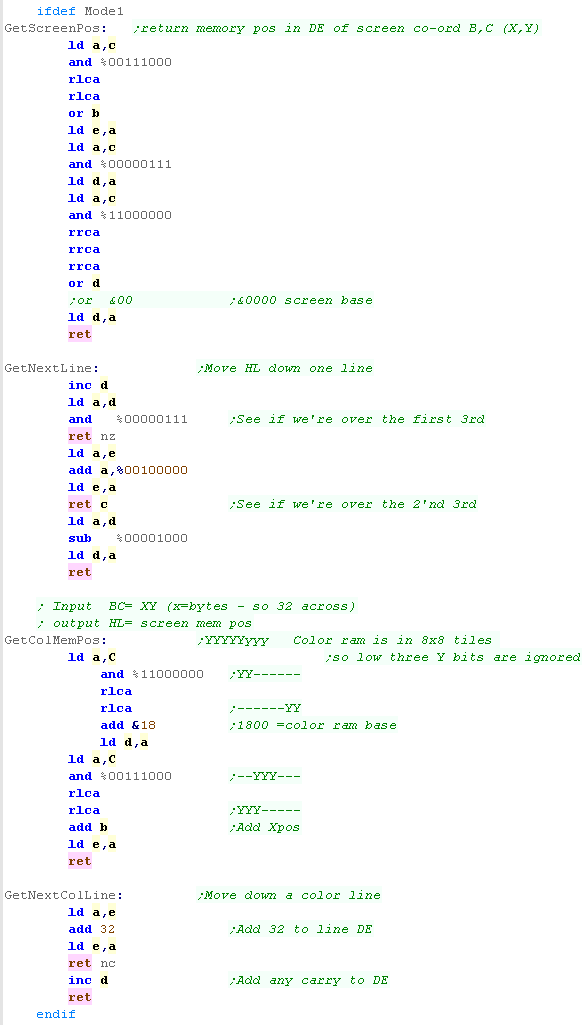
 |
||||
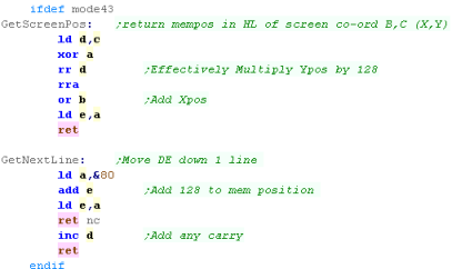
| GetScreenPos will multiply the Y position by 128, and add the X
byte... returning screen location in DE GetNextLine will add 128 to the memory address - moving DE down a line |
 |
||||
| We include our sprite data from binary files on disk. | 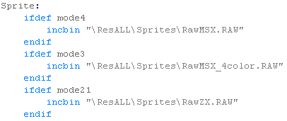 |
||||
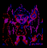
| Here are the results! |
|
| Mode
4 is the best for games... 3 is higher resolution, so is good
for word processing... Mode 1 is just for Speccy emulation, so if you want to port a spectrum game and make your SAM look like a 48k speccy, then go ahead! Mode 2 is a bit odd... it's not quite like the MSX1 (MSX1 uses 4 bits for Foreground / Background color info - SAM uses just 3), but very similar, it could be handy if you need a screen with a smaller ram footprint for faster game play. |
|
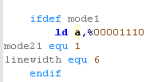
Using Mode 1
| We need different screen mode settings for mode 1... Our Set mode and pixel drawing routines are the same however. |
 |
| Because of the annoyingly complex screen layout, we have quite a
big GetScreenPos and GetNextLine routine. We also need to set the color information, which is in a different format again... the format is more simple for the color information, however which makes things easier. |
 |
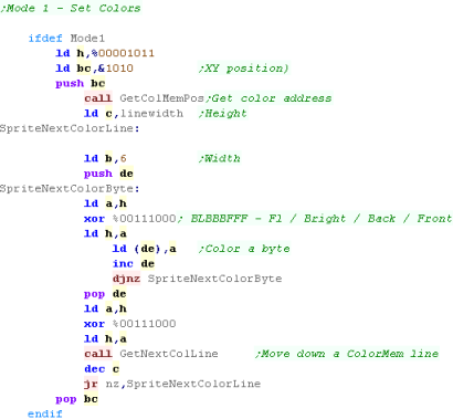
| We set the pixel data with the same routine from Mode 4/3, but
we set the color info separately. We're setting all the 8x8 color blocks foreground to color 3, and background to color 1, but we're flipping the background to 6 every other block |
 |
| Here is the result | 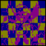 |
Using Mode 2
| We need to use a different screen mode settings for mode 2 | 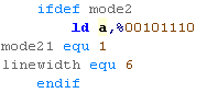 |
| Screen mode 2's layout is much simpler... there are 32 bytes per line, and each line is consecutive in memory | 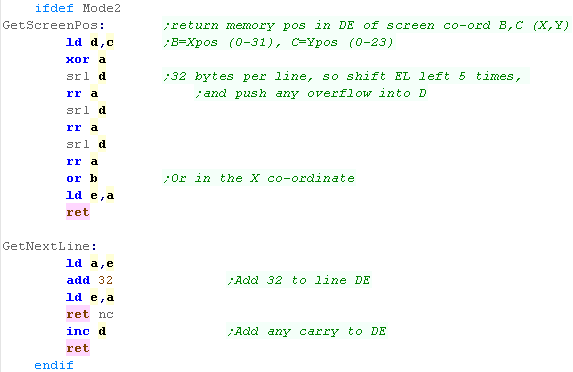 |
| We set the pixel data with the same routine from Mode 4/3, but
we set the color info separately. The routine is basically the same as our main pixel data, we just need to offset the address of writes by &2000 |
 |
| The palette data is in the same format as Mode 1 - but the colors cover 8 pixels in a 8x1 configuration | 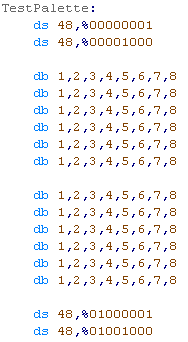 |
| Here are the results | 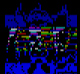 |
Cleaning up our mess, and playing with
colors!
| We use port 250 to reset the low ram area and turn off screen ram. | 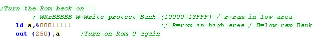 |
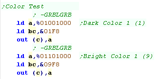
| If we want to change colors, we use ports &xxF8, where xx is
00-0F for colors 0-15 these take a byte in the format %-GRBLGRB... with 2 Green, Red and Blue bits, and 1 Light bit, which slightly increases brightness of all colors |
 |
|
All these
examples have shown the video being mapped to &0000+... you
can map it somewhere else if you prefer! With modes 1+2, it would probably make sense to map it to &4000-&7FFF, so you can still use Interrupt Mode 1... Remember, the example code for these tutorials is at &8000... so you can't do anything with the &8000-&FFFF bank! |
 |
Lesson
P59
- Hardware scrolling on the MSX 1/2/2+ The MSX has some scrolling options - but they vary depending on the MSX revision Lets take a look at all the options! |
 |
 MSX1_Scroll.asm
MSX2_Scroll.asm
|
 |
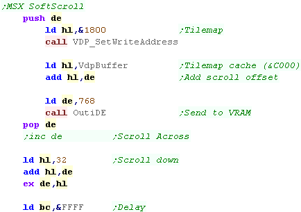
MSX1 Soft Scrolling the tilemap
| The MSX1 has no real
hardware scrolling options, but as the tilemap is just 768 bytes,
we can just update the entire tilemap in one go. By offsetting the source by +1/-1 we can move the tilemap left or right... by offsetting by +32 / -32 we can move the tilemap up or dow Of course, this will restrict the movement to 8x8 blocks |
 |
| The tilemap effectively scrolls by 1 block at a time. | 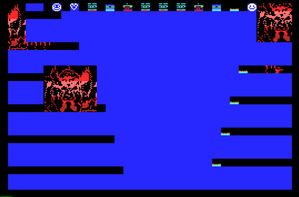 |
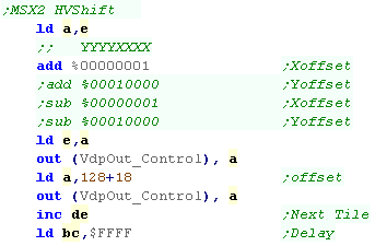
MSX2 Shifting the tilemap (Limited)
| The MSX 2 has an 'offset'
option - this allows us to 'shift' the screen.... this uses a
single byte... This uses Reg #18 The Top Nibble is the Y offset... the bottom nibble is the X offset |
 |
| This can be done in combination with the 'soft scroll' above to
move the screen 7 pixels, before jumping back and updating the
tilemap via software. We're using the top 3 bits of DE for the 'offset', We use the remaining bits as a scroll for the soft tilemap. |
 |
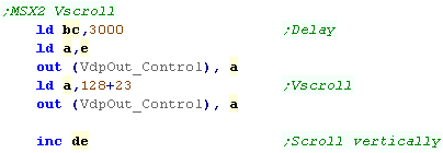
MSX2 Vertical Scroll
| While we can only horizontally scroll via the method above, The
MSX2 has full vertical hardware scroll via Reg #23. This will scroll the full 256 pixel tall page... though only 192 pixels are visible by default. |
 |
| Here is the result | 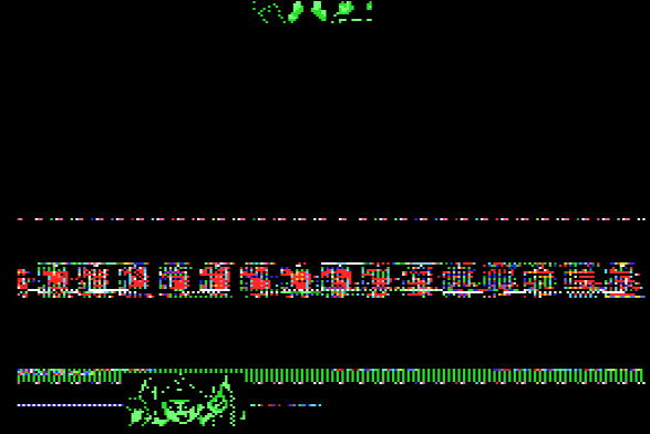 |
MSX2+ Horizontal Scroll
| The MSX2+ has added
horizontal scroll... it uses 3 registers... #25,#26 and #27 #27 has the bottom 3 bits of the scroll... #26 has the remaining 6 bits of the scroll position. This allows up to 512 pixels of scroll. |
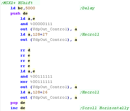 |
| On the Bitmap screen we have some extra options!... these use
Reg #25 By default scroll will hide the left side 8 pixels... NoMask will disable this 2 Pages will cycle between pages 1 and 2 for a 512 pixel logical screen - we need to select page 1 for this with Reg #2 |
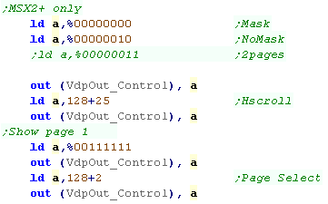 |
| Here is the result... the first page is going off the right, and
the second is coming in... Note this has no effect on the V-scroll... which still only shows 1 page... so the 'logical screen' is 512 x 256 |
 |
|
Many of these options
work on the Bitmap and Tilemap screens... You'll need to run the program code to see the effect... or watch the video! |
| View Options |
| Default Dark |
| Simple (Hide this menu) |
| Print Mode (white background) |
| Top Menu |
| ***Main Menu*** |
| Youtube channel |
| Patreon |
| Introduction to Assembly (Basics for absolute beginners) |
| Amazon Affiliate Link |
| AkuSprite Editor |
| ChibiTracker |
| Dec/Bin/Hex/Oct/Ascii Table |
| Alt Tech |
| Archive.org |
| Bitchute |
| Odysee |
| Rumble |
| DailyMotion |
| Please note: I wlll upload more content to these alt platforms based on the views they bring in |
| 68000 Content |
| ***68000 Tutorial List*** |
Learn 68000 Assembly  |
| Hello World Series |
| Platform Specific Series |
| Simple Samples |
| Grime 68000 |
| 68000 Downloads |
| 68000 Cheatsheet |
| Sources.7z |
| DevTools kit |
| 68000 Platforms |
| Amiga 500 |
| Atari ST |
| Neo Geo |
| Sega Genesis / Mega Drive |
| Sinclair QL |
| X68000 (Sharp x68k) |
| 8086 Content |
| Learn 8086 Assembly |
| Platform Specific Series |
| Hello World Series |
| Simple Samples |
| 8086 Downloads |
| 8086 Cheatsheet |
| Sources.7z |
| DevTools kit |
| 8086 Platforms |
| Wonderswan |
| MsDos |
| ARM Content |
| Learn ARM Assembly |
| Learn ARM Thumb Assembly |
| Platform Specific Series |
| Hello World |
| Simple Samples |
| ARM Downloads |
| ARM Cheatsheet |
| Sources.7z |
| DevTools kit |
| ARM Platforms |
| Gameboy Advance |
| Nintendo DS |
| Risc Os |
| Risc-V Content |
| Learn Risc-V Assembly |
| Risc-V Downloads |
| Risc-V Cheatsheet |
| Sources.7z |
| DevTools kit |
| MIPS Content |
| Learn Risc-V Assembly |
| Platform Specific Series |
| Hello World |
| Simple Samples |
| MIPS Downloads |
| MIPS Cheatsheet |
| Sources.7z |
| DevTools kit |
| MIPS Platforms |
| Playstation |
| N64 |
| PDP-11 Content |
| Learn PDP-11 Assembly |
| Platform Specific Series |
| Simple Samples |
| PDP-11 Downloads |
| PDP-11 Cheatsheet |
| Sources.7z |
| DevTools kit |
| PDP-11 Platforms |
| PDP-11 |
| UKNC |
| TMS9900 Content |
| Learn TMS9900 Assembly |
| Platform Specific Series |
| Hello World |
| TMS9900 Downloads |
| TMS9900 Cheatsheet |
| Sources.7z |
| DevTools kit |
| TMS9900 Platforms |
| Ti 99 |
| 6809 Content |
| Learn 6809 Assembly |
| Learn 6309 Assembly |
| Platform Specific Series |
| Hello World Series |
| Simple Samples |
| 6809 Downloads |
| 6809/6309 Cheatsheet |
| Sources.7z |
| DevTools kit |
| 6809 Platforms |
| Dragon 32/Tandy Coco |
| Fujitsu FM7 |
| TRS-80 Coco 3 |
| Vectrex |
| 65816 Content |
| Learn 65816 Assembly |
| Hello World |
| Simple Samples |
| 65816 Downloads |
| 65816 Cheatsheet |
| Sources.7z |
| DevTools kit |
| 65816 Platforms |
| SNES |
| eZ80 Content |
| Learn eZ80 Assembly |
| Platform Specific Series |
| eZ80 Downloads |
| eZ80 Cheatsheet |
| Sources.7z |
| DevTools kit |
| eZ80 Platforms |
| Ti84 PCE |
| IBM370 Content |
| Learn IBM370 Assembly |
| Simple Samples |
| IBM370 Downloads |
| IBM370 Cheatsheet |
| Sources.7z |
| DevTools kit |
| Super-H Content |
| Learn SH2 Assembly |
| Hello World Series |
| Simple Samples |
| SH2 Downloads |
| SH2 Cheatsheet |
| Sources.7z |
| DevTools kit |
| SH2 Platforms |
| 32x |
| Saturn |
| PowerPC Content |
| Learn PowerPC Assembly |
| Hello World Series |
| Simple Samples |
| PowerPC Downloads |
| PowerPC Cheatsheet |
| Sources.7z |
| DevTools kit |
| PowerPC Platforms |
| Gamecube |
| Work in Progress |
| ChibiAndroids |
| Misc bits |
| Ruby programming |
Buy my Assembly programming book
on Amazon in Print or Kindle!


Available worldwide!
Search 'ChibiAkumas' on
your local Amazon website!
Click here for more info!


Buy my Assembly programming book
on Amazon in Print or Kindle!
Available worldwide!
Search 'ChibiAkumas' on
your local Amazon website!
Click here for more info!
Buy my Assembly programming book
on Amazon in Print or Kindle!
Available worldwide!
Search 'ChibiAkumas' on
your local Amazon website!
Click here for more info!