The Gameboys do not use a Z80...
some people say they do, but those people are wrong! it has MANY
features of a Z80... but MANY others are weird... and some are even
BUGGY! So why might we want to use it... well, the gameboy+GBC sold 118 MILLION!... compared to the ZX spectrum's puny 5 million... the gamegears 10 million, the Master system's 13 million... the Gameboy gives the 'real z80' systems a spanking! We can't use a normal Z80 assembler to develop for it, but Vasm in 'OldStyle' mode will compile for it, just use the switch '-gbz80' and it will compile compatible code! |
![]() |
![]() |
![]() |
The Gameboy Color is just a Gameboy
with a few 'power ups', The best thing is, if we limit ourselves a
bit, we can write games that have full color on the GBC, but still
play the same on the Classic Gameboy! Lets take a look at the GB and GBC specs! Specs:
|
![]() ![]() |
![]() |
If
you
want to learn GBZ80 get the Cheatsheet!
it has all the Z80 commands, but higlights the ones missing
on the GBZ80 - as well as the extra commands that the GBZ80
posesses, and the commands with different bytecode... You can use it for both your Z80 and GBZ80 development! |
![]() |
ChibiAkumas Tutorials
Normal Registers | Shadow Registers | |||
Accumulator | A | A' | ||
flags | F | F' | ||
HighLow Memory Location | H | L | H | L |
ByteCount | B | C | B | C |
DEstinaton | D | E | D | E |
Indirect X - IX | IXH | IXL | ||
Indirect Y - IY | IYH | IYL | ||
Program Counter | PC | |||
Stack Pointer | SP | |||
Refresh | R | |||
Interrupt point | I |
Flags are DIFFERENT on the GBZ80!
Bit |
Flag |
Name |
Description |
---|---|---|---|
7 |
Z |
Zero |
Zero Flag (1=zero) |
6 |
N |
Add / Subtract |
1=Subtract occurred, Used by DAA |
5 |
H |
Half Carry |
Used by DAA |
4 |
C |
Carry |
Carry / Borrow |
3 |
- |
|
|
2 |
- |
|
|
1 |
- |
|
|
0 |
- |
|
|
The Gameboy,Gamegear and Mastersystem
screens do not work like they do on computers like the CPC Graphics are not just 'bytes' in a memory address... The screen is made up of a 'Tile Layer' and a 'Sprite Layer' To explain Tiles and sprites, lets look at our imaginary game shown to the right 'The Super Yuusha Siblings', on a theoretical game system the 'GameChibi'... Just to be very clear, we looking at this as a concept, not the actual layout of the gameboy! Looking at our example, We have a level with some grass, blocks, and some collectable 'stars'... our hero, Yume is controlled by the player... |
![]() |
The screen is made up of the Tile
layer, and the Sprite Layer, Usually Sprites are drawn above the Tiles... but sometimes they may be drawn below. It's also possible we could use sprites for the stars.. but sprites are very limited, so the object doesn't move, then tiles will do the job... we can even animate the stars by switching the tile between different patterns |
![]() |
The tile array on the systems we'll
be looking at is made up of 8x8 tiles... the array is a 'grid' of
these tiles, so the tiles must line up, a block cannot be at a 'half
way boundary' Tiles are defined by a number (usually 0-255)... we define the bitmap (image) data for that tile (we'll call it a pattern), then tell the hardware what positions in the tile array to use that pattern. In our example, the black background is pattern 0 ... the blocks are pattern 1... the grass is pattern 2... and the stars are pattern 3 Our 'GameChibi' console has a tile array of 8x8... and 64 bytes is used to define the tile grid... So to define the stars, we need to set memory locations 10,20 and 15 of the tile array to byte '3' A real system usually has a tile array bigger than the screen (maybe just by one row and one coumn)... this is to allow smooth scrolling of the screen, where two tiles are 'half shown' Now in the case of our 'GameChibi' system, with it's 64 tile screen, and 256 pattern definitions, we could just set every visible tile to a different pattern, and treat the screen as a plain bitmap again... We can do that on the MSX1, but unfortunately the Gameboy and Mastersystem have too few tiles for their screen size, so some parts of the screen must contain the same tile! |
![]() |
Because our system is using hardware sprites, we have to design
our game sprites in a way that can be drawn with the hardware
sprites... for example lets look at our Yume sprite... if our
'GameChibi' used 8x8 hardware sprites, we would have to use 48 of
them to make this image!... we can save 6 (marked green)... these
have no data, so we can just not draw them... When it comes to moving our character, the software will have to move the hardware sprites all together, so the user does not realise they are made up of many sprites!... on systems with more onscreen colors than sprite colors, two or more sprites may be overlapped to make the sprite appear more colorful Most systems will have one color (usually 0) which marks the transparent colour. but there is a problem! with software sprites on a bitmap screen, we can draw as much as we want, it will just get slow.... but with hardware sprites, we have a fixed limit of how many sprites can be shown onscreen at once! sounds bad? well actually it's worse, even though a system like the gameboy can show 40 sprites onscreen, there can only be 10 on a line... if more than 10 appear on the same line, some will flicker, or not appear... there's nothing we can do about it, we just have to design our game to avoid this problem! |
![]() |
The cartridge is loaded into the
system memory as the ROM... The first &160 bytes of the
cartridge contain the RST calls and GBZ80 Interrupt calls Next come the header, which tells the gameboy what the cartridge contains... there is also a checksum, which must be correct for the game to work on a real gameboy - though it should work on emulators without it! (the tool rgbfix.exe will work out the checksum for you!) A note on the interrupts between &0040-&0060: Interrupts can be enabled or disabled as needed, but it's best to put a 'RETI' (Return and enable interupts) at &0040-&0060 |
|
The Rom cartridge (and its header)
take up the first &8000 bytes of memory, The 8k of ram is accessible at &C000-&DFFF... a 'shadow copy' is also at &E000-&FDFF (some cartridges have extra ram at this address) |
|
Section | Addr | Name | Bits | Bit Meaning | |
Joy | FF00 | P1/JOYP - Joypad (R/W) | --BD3210 | B=Buttons D=Direction 3210=buttons DULR SSBA | |
Serial | FF01 | SB - Serial transfer data (R/W) | 8 Bits of data | ||
Serial | FF02 | SC - Serial Transfer Control (R/W) | S-----SC | SC - Serial Transfer Control (R/W) | |
Timer | FF04 | DIV - Divider Register (R/W) | |||
Timer | FF05 | TIMA - Timer counter (R/W) | |||
Timer | FF06 | TMA - Timer Modulo (R/W) | |||
Timer | FF07 | TAC - Timer Control (R/W) | -----SCC | S=Stary CC=Clockspeed | |
INT | FF0F | IF - Interrupt Flag (R/W) | |||
Sound | FF10 | NR10 - Channel 1 (Tone & Sweep) Sweep register (R/W) | -TTTDNNN | T=Time,D=direction,N=Numberof shifts | |
Sound | FF11 | NR11 - Channel 1 (Tone & Sweep) Sound length/Wave pattern duty (R/W) | DDLLLLLL | L=Length D=Wave pattern Duty | |
Sound | FF12 | NR12 - Channel 1 (Tone & Sweep) Volume Envelope (R/W) | VVVVDNNN | C1 Volume / Direction 0=down / envelope Number (fade speed) | |
Sound | FF13 | NR13 - Channel 1 (Tone & Sweep) Frequency lo (Write Only) | LLLLLLLL | pitch L | |
Sound | FF14 | NR14 - Channel 1 (Tone & Sweep) Frequency hi (R/W) | IC---HHH | C1 Initial / Counter 1=stop / pitch H | |
Sound | FF16 | NR21 � Channel 2 (Tone) Sound Length/Wave Pattern Duty (R/W) | DDLLLLLL | L=Length D=Wave pattern Duty | |
Sound | FF17 | NR22 - Channel 2 (Tone) Volume Envelope (R/W) | VVVVDNNN | C1 Volume / Direction 0=down / envelope Number (fade speed) | |
Sound | FF18 | NR23 - Channel 2 (Tone) Frequency lo data (W) | LLLLLLLL | pitch L | |
Sound | FF19 | NR24 - Channel 2 (Tone) Frequency hi data (R/W) | IC---HHH | C1 Initial / Counter 1=stop / pitch H | |
Sound | FF1A | NR30 - Channel 3 (Wave Output) Sound on/off (R/W) | E------- | 1=on | |
Sound | FF1B | NR31 - Channel 3 (Wave Output) Sound Length | NNNNNNNN | Higher is shorter - no effect unles C=1 in FF1E | |
Sound | FF1C | NR32 - Channel 3 (Wave Output) Select output level (R/W) | -VV----- | VV=Volume (0=off 1=max 2=50% 3=25%) | |
Sound | FF1D | NR33 - Channel 3 (Wave Output) Frequency's lower data (W) | LLLLLLLL | Low frequency | |
Sound | FF1E | NR34 - Channel 3 (Wave Output) Frequency's higher data (R/W) | RC---HHH | H=high frequency C=counter repeat (loop) R=Restart sample | |
Sound | FF20 | NR41 - Channel 4 (Noise) Sound Length (R/W) | ---LLLLL | L=Length | |
Sound | FF21 | NR42 - Channel 4 (Noise) Volume Envelope (R/W) | VVVVDNNN | Volume / Direction 0=down / envelope Number (fade speed) | |
Sound | FF22 | NR43 - Channel 4 (Noise) Polynomial Counter (R/W) | SSSSCDDD | Shift clock frequency (pitch) / Counter Step 0=15bit 1=7bit (sounds electronic)/ Dividing ratio (roughness) | |
Sound | FF23 | NR44 - Channel 4 (Noise) Counter/consecutive; Inital (R/W) | IC------ | C1 Initial / Counter 1=stop | |
Sound | FF24 | NR50 - Channel control / ON-OFF / Volume (R/W) | -LLL-RRR | Channel volume (7=loud) | |
Sound | FF25 | NR51 - Selection of Sound output terminal (R/W) | LLLLRRRR | Channel 1-4 L / Chanel 1-4R (1=on) | |
Sound | FF26 | NR52 - Sound on/off | A---4321 | read Channel 1-4 status or write All channels on/off (1=on) | |
Sound | FF30 � FF3F | Wave Pattern RAM | HHHHLLLL | 32 4 bit samples | |
LCD | FF40 | LCDC - LCD Control (R/W) | EWwBbOoD |
E=enable
screen W=Window addr (&9C00/9800) w=window display on B=Background pattern addr (&8000/8800) b=background tilemap addr (&9800/9C00) O=Object sprite size 1=8x16... o=Object Sprites enable ... D=Background display |
|
LCD | FF41 | STAT - LCDC Status (R/W) |
|
Ly
coincidence interrupt on, Oam Interrupt on, Vblank interrupt on,
Hblank interrupt on, Coincidence flag, MM=video mode (0/1 =Vram
available) |
|
Tile | FF42 | SCY � Tile Scroll Y | 0= default |
||
Tile | FF43 | SCX � Tile Scroll X | 0= default | ||
LCD | FF44 | LY - LCDC Y-Coordinate (R) - LCD Y Line (0-153 144+ are V-Blank) | |||
LCD | FF45 | LYC - LY Compare (R/W) | |||
RAM | FF46 | DMA - DMA Transfer and Start Address (W) | Sprite DMA -
High byte of DMA - must be executed from &FF80-FFFE |
||
Tile | FF47 | BGP - BG Palette Data (R/W) - Non CGB Mode Only | |||
Sprite | FF48 | OBP0 - Object Palette 0 Data (R/W) - Non CGB Mode Only | |||
Sprite | FF49 | OBP1 - Object Palette 1 Data (R/W) - Non CGB Mode Only | |||
Tile | FF4A | WY - Window Y Position (R/W) | |||
Tile | FF4B | WX- Window X Position minus 7 (R/W) | |||
CPU | FF4D | KEY1 - CGB Mode Only - Prepare Speed Switch | C------P | C=Current speed P=prepare switch | |
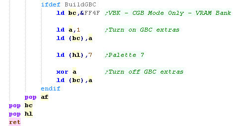
VRAM | FF4F | VBK - CGB Mode Only - VRAM Bank | -------B | B=Bank | |
COM | FF56 | RP - CGB Mode Only - Infrared Communications Port | |||
Tile | FF68 | BCPS/BGPI - CGB Mode Only - Background Palette Index | Select
background palette byte |
||
Tile | FF69 | BCPD/BGPD - CGB Mode Only - Background Palette Data | Write background palette byte |
||
Sprite | FF6A | OCPS/OBPI - CGB Mode Only - Sprite Palette Index | Select sprite palette byte |
||
Sprite | FF6B | OCPD/OBPD - CGB Mode Only - Sprite Palette Data | Write sprite palette byte |
||
RAM | FF70 | SVBK - CGB Mode Only - WRAM Bank (bits 0-3 =0-2) | -----BBB |
BBB=Bank 1-7
(0 also pages in bank 1) |
|
INT | FFFF | IE - Interrupt Enable (R/W) | ---JSTLV | J=Joypad S=Serial T=Timer L=Lcd stat V=vblank |
Larger cartridges can have more than
32k rom, and even extra RAM built into them (With battery backup!) We switch cartridge RAM/ROM bank by writing to specific address ranges within the 'ROM'... this tells the cartridge to change bank... Good example addresses are shown below... though actually a range of addresses will have the same effect |
|
Joypad reading is all done with
memory address &FF00 Only Bits 0-3 in this address contain the state of the buttons, we first need to select which half of the joystick we want to read. If we write %11101111 to &FF00 (Bit 4 is zero) we will select the direction controls. We can then read from &FF00 to get Down, Up, Left, Right in bits 0-3 If we write %11011111 to &FF00 (Bit 5 is zero) we will select the button controls. We can then read from &FF00 will get Start, Select, Button B, Button A in bits 0-3 |
|
Sprite Data is stored from &FE00 onwards, there are 40
sprites, and each definition uses 4 consecutive bytes... For Example, Sprite 0's bytes are highlighted in black... it has a Y co-ordinate, an X co-ordinate, a Tile Number, and tile Attributes Y and X are offset, so you can have a sprite partially off the screen, You need to set XY to (8,16) to get the top corner of the screen (0,0) Attributes:
On GBC sprites use an alternate 8 palettes to background tiles. Sprites are all 8x8 or 8x16, which is define by bit 2 of &FF40 (LCDC - LCD Control) |
||||||||||||||||
![]() |
Gameboy & Gameboy Color Links
Visual Boy Advance -
Emulates the Gameboy , Gameboy Color, and others!
GameBoy Dev'rs -
Gameboy programming website
Color
Programming - The only site I can find with examples about Color on
the gameboy!
Vasm - You can't easilly
compile for the gameboy with a standard Z80 assembler like WinApe...
but VASM in 'OldStyle' mode is pretty similar to WinApe