


| Load up WinApe , Select Show Assembler from the Assembler menu | 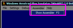 |
| We need to define a start for our program in memory... BASIC and
the firmware need the first chunk, so memory address &1200 is
a good starting point to start your program at &1200 add the command ORG &1200 |
 |
Drawing an 8x8 sprite
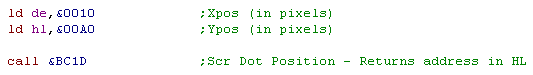
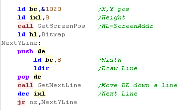
| First we want to get the memory address of the screen we want to
draw to... We need to specify the co-ordinates of the pixel we want... We specify the X position in DE (from the left of the screen) We specify the Y position in HL (from the bottom of the screen) Then we call &BC1D (SCR DOT POSITION)... this will return the screen byte position in HL |
 |
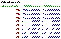
| We need some bitmap data... In Mode 1 each pixel is 2 bits - so 2
bytes are each line... a bit set in just the left hand nibble of each byte defines color 1, a bit in the right hand sets color 2... a bit in both sides sets color 3 |
 |
| As we have the destination in HL, We're going to store the source
address of the bitmap in DE We'll load the line count in B - our bitmap is 8 lines |
 |
| We're going to draw a line... first we need to back up HL into the stack with PUSH... we need it in a moment.. Next we load a byte from address DE... and write it to HL... and increase HL and DE... We do this twice for the two bytes of the line |
 |
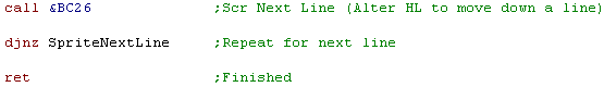
| now we need HL from before... we want to move down a screen line
line We call &BC26 to do this (SCR NEXT LINE)... this updates HL for our next line... We decrease B and repeat the line routine until our tile is drawn, then we return! |
 |
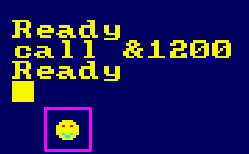
| To run this test, type CALL &1200 in basic The resulting sprite is shown to the screen! |
 |
| We could do the same for 16 color sprites in mode 0 -
which uses 4 bits per pixel, but the byte layout is a lot more
confusing! We can load A with 0 and CALL &BD1C (MC SET MODE) to set screen mode 0 |
 |
Extending the example for larger sprites.
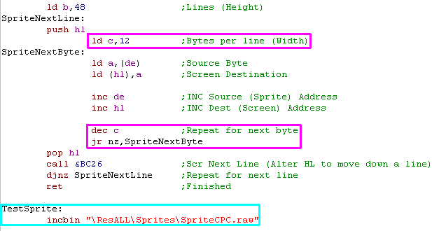
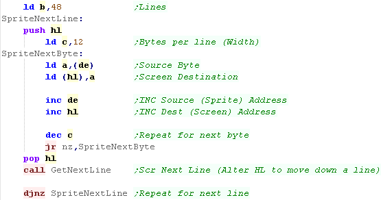
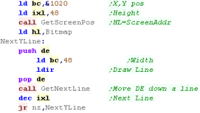
| With just a few changes we can make our previous code work with
larger sprites (of any size)... we're going to show a 48x48 sprite We're going to use C as a 'Line Bytecount' and repeat the byte copy routine several times per line until C reaches Zero. We'll import the byte data from a file using INCBIN |
 |
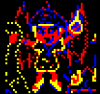
| The sprite will be shown on screen! | |
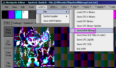
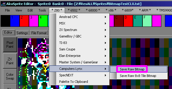
| How did we create the sprite? Well, we can use my AkuSprite
Editor! This can export a bitmap to the correct byte format for the screen of all the systems covered in my tutorials! The 'Save Raw Bitmap' option in the CPC / FILE menu will create the data file used in today's tutorial. The program also supports 16 color Mode 0 sprites! |
 |
 |
Our bitmap is on
the screen... but the colors of our chibiko character are wrong Maybe we can fix that with firmware function &BC32 (SCR SET INK)... but you'll have to figure that out yourself! |

Calculating Screen position for bitmaps and colors
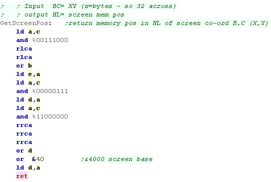
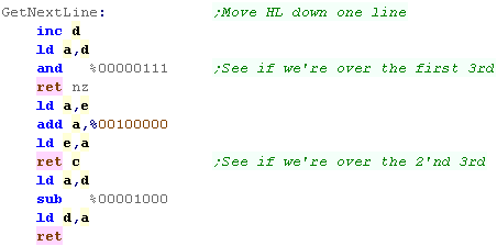
| We're going to need to be able to calculate the screen ram
position, for two purposes... First we'll do the more complex screen co-ordinates... The screen layout is weird... the final HL address is made up of the bits in the following format: 0 1 0 Y7 Y6 Y2 Y1 Y0 Y5 Y4 Y3 X4 X3 X2 X1 X0 The X bits are all at the bottom - so moving across the screen is easy, but moving down is a pain - so long as we're in an 8 pixel tall strip (effectively a character block) we can just INC D, but beyond that we have to do some work!... the top 3 bits are always %010 - because the screen base is &4000 We need a version call ed GetScreenPos... which coverts (X,Y) position (B,C) to a DE memory address - we'll use this to calculate the screen memory position of a byte we want to write... We specify the X position in bytes... and the Y position in lines Once we've written one line, we need to move down the screen, If we're aligned to an 8x8 block, we can just INC D... but otherwise we'll need something more complex, we've got a 'GetNextLine' function to do this for us. |
  |
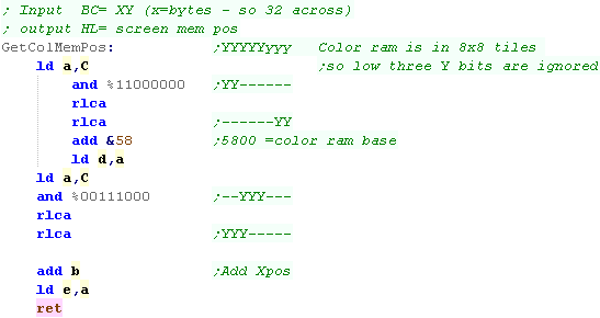
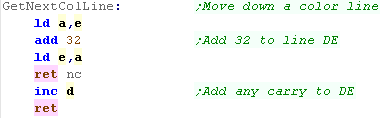
| Color data is simpler... the data is 'linear'... but there is only
1 byte for each 8x8 square... If we work out which 8x8 block we're in (by ignoring the low 3 bits of the Y co-ordinate) we just need to multiply that Y-block number by 32... we do this by bit-shifting If we want to move down a line, we just add 32 to DE |
  |
Drawing an 8x8 sprite
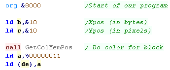
| Ok, we're going to draw a simple sprite... because our sprite is a
single 'square', we just need to color one block. Our program starts at address &8000 - this is where our loader basic file will run First we set B and C with the X,Y Co-ordinate of the sprite destination... then we use GetColMemPos to set DE to the destination... We write %00000011 to set the block to magenta! |
 |
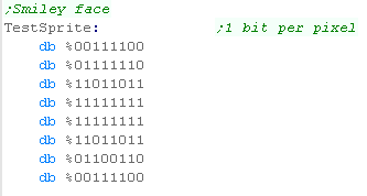
| We need some bitmap data!... we're going to define a smiley face
for a sprite.. The sprite is 8x8 - and each byte stores 8 pixels... so the whole 8x8 sprite is just 8 bytes |
 |
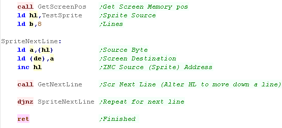
| Lets draw the pixel data! We use the GetScreenPos to calculate the location in RAM... and then load HL with the sprite source... We need to copy just one byte for each line, using GetNextLine after each one... we use B as a line counter, so we repeat the procedure 8 times. |
 |
| The result can be seen here! | 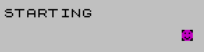 |
 |
The example
above is very simple, so the color drawing part is just a single 1
byte write... it will be more complex if we're doing a bigger
area! |
Drawing a Larger sprite
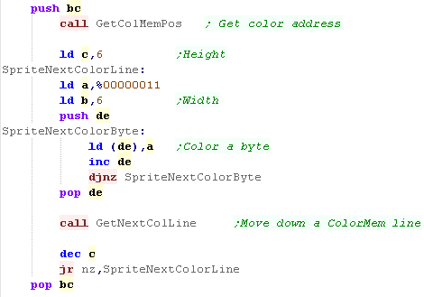
| This time we're going to use a larger sprite - 48x48 pixels... When it comes to the color are, this equates to a 6x6 area... We use C as the Y counter... and B as the X counter... We back up the destination with a PUSH/POP DE so we can calculate a line down with GetNextColLine. |
 |
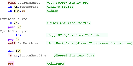
| We now need to draw our bitmap data, we use GetSpritePos to set DE
to the screen memory location We set HL to the source bitmap... We're going to use IXH as the line count - our bitmap is 48 lines tall... We're setting BC to 6 - the width of the bitmap in bytes... why BC rather than just B? we're going to use LDIR - which will copy BC bytes from the source HL to the destination DE Once we've done a line, we restore the start position by POPping DE... and use GetNextLine... we then decrease our IXH counter and repeat |
 |
| The result can be seen here. | 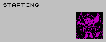 |
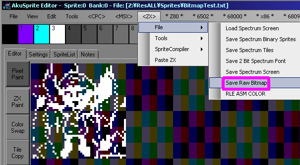
| If you want to covert bitmap data, you can use my AkuSprite
Editor... it supports all the systems in these tutorials... The 'SaveRawBitmap' option on the ZX menu will save a black and white bitmaps. |
 |
| The example above
filled the entire sprite a single color - if we wanted to set the
36 color blocks to different colors, we'd want a second 'colormap'
bitmap for the sprite which would color it in. |
 |

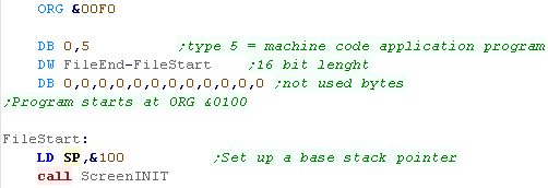
Starting our Program
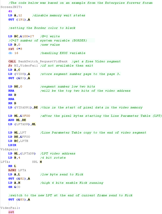
| Lets start our Enterprise program! First we need a heade to start our program, and set up a valid stack pointer... next we want to initialize our graphics screen! |
 |
| Uhh, this is complex - so we're not going to go in detail! Effectively, we need to get a valid 16k ram bank from the OS... we keep requesting ram until we find one, and set it up as the screen when we do. This code was taken from a sample from the Enterprise Forever forum... fortunately we don't really need to change it - so we can just run it and trust it to work! |
|
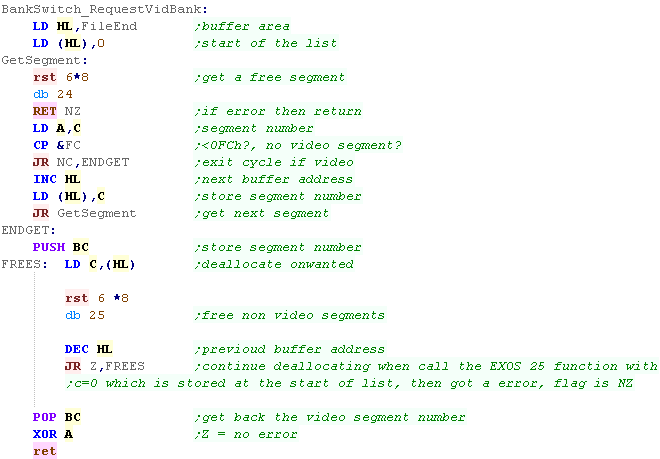
| The function aboves uses a RequestVidBank function to get the ram
banks... We don't need to worry about how this works, it'll just do the job for us! |
 |
| Ok, this is a bit we may want to change... The Enterprise screen uses a 'LPT' table - this defines the size of the screen... our default screen is 320x200 - and we probably want to leave it that way, but we may want to change the color depth and the colors... There are 8 definable colors - in 4 color mode half are unused - in 16 color mode, only 8 can be defined - the other 8 are the same with a 'Color Bias'... but that's outside of what we're going to cover today! |
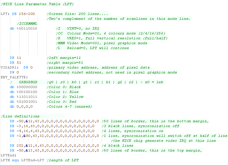 |
| The Enterprise screen doesn't HAVE to be 320x200 - we
can make it bigger by changing the borders and margins, we can even
change the memory layout to make the screen work exactly like a CPC
screen... We're not going to look at that here though, as the Enterprise screen layout is more logical than the CPC one, and a bigger screen would use more than 16k of our memory |
|
Calculating Screen position by X,Y co-ordinate
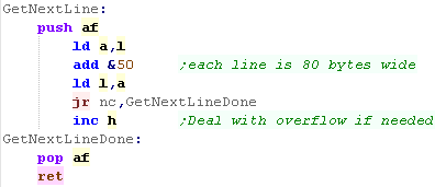
| When we want to draw some data to the screen, we need to calculate
the memory address of any pixel we want to change. The formula for the enterprise is really simple... Memory address = &C000 + ( Ypos * 80) + Xpos &50 (80 in hex) is %01010000... we can effect a multiply by shifting the Y position to each of the '1' bits, and adding the two together We just then add the base &C000 and the Xpos... and HL will contain the final address... Don't worry if you don't understand this... you can just use this code as is! |
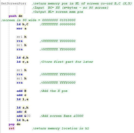 |
| Moving down a line on the Enterprise is far easier than systems
like the Speccy and the CPC... Because each line is directly below the previous, we just add &80 to L If L goes over 255, we need to INC H as well |
 |
Drawing an 8x8 sprite
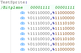
| We're going to need to define a sample sprite... here's a smiley
face! Each 8 pixel line is 2 bytes... so 16 bytes in total... The format is a little odd... each byte is split into 2 nibble 'bitplanes'.... %11110000 is color 1... %00001111 is color 2... %11111111 is color 3... there are no prizes for guessing color 0's bit definition! |
 |
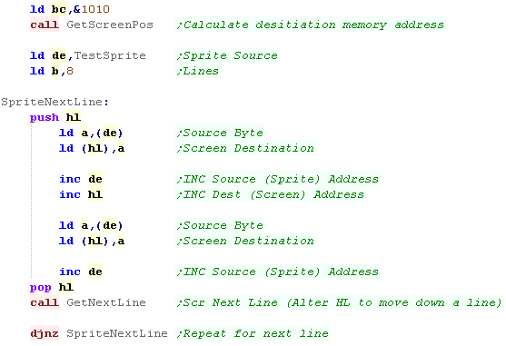
| Ok, we need to draw our sprite! We set BC to the XY position we want to draw our sprite... this sets HL to the video memory address... We load DE with the sprite data source address... we also load B with the number of Y lines We back up HL for later... then we read two bytes from DE and write them to HL... increasing DE and HL Once we've done a line, we restore DE, and use GetNextLine to move down the screen... We then decrease B and repeat. |
 |
| The resulting sprite can be seen! | 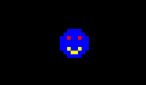 |
| The example above
filled the entire sprite a single color - if we wanted to set the
36 color blocks to different colors, we'd want a second 'colormap'
bitmap for the sprite which would color it in. |
|
Drawing a bigger sprite
| What if we want a bigger sprite? Lets use a 48x48 sprite In this example we'll set B to 48 - as our sprite is 48 lines tall... This time we'll need a loop for drawing the bytes horizontal line - we'll use C for this... 48 pixels is 6 bytes... so we set C to 6 |
 |
| We've drawn the Chibiko character to screen! Of course this same code can do any size of sprite, we just need to change the B and C values. |
 |
| You can export a valid Enterprise sprite using my AkuSprite Editor - it's free and open source, and is included in the sources.7z file. | 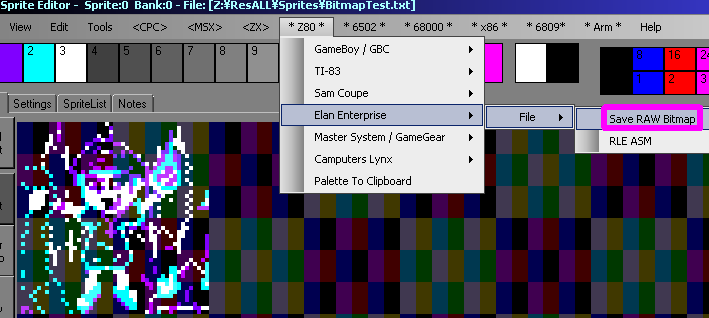 |
 |
16 Color mode
on the Enterprise is exactly the same.... it's half the
resolution, and the bit layout of each byte is different (it's the
same as the CPC), but the procedure to copy to the screen is
exactly the same, Akusprite Editor can also output the correct format for 16 color Enterprise modes! |
Getting started
| Ok, Let's get started!... First we need our program to start somewhere... We're going to start at &8000... we need to start somewhere other than &0000-&7FFF, as we'll page that ram out and in for our video. Ok, let's prep a stack pointer... again it's got to be above &BFFF for safety, so we'll load it to &BFFF |
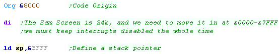 |
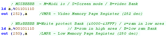
| Right! lets get things set up. Let's turn off interrupts with a DI... interrupts will typically call &0038, and we want to swap out the &0000-&7FFF memory area with screen memory. We need to define a pair of banks of ram for our screen... we'll use banks 14 and 15... the last two banks of a 256k machine (the minimum spec for the SAM)... we do this with port 252 We need to configure the low area... by default it's ROM - we need to turn of that and set it as RAM with bit 5... we also need to set the low ram bank to set that banks 14 & 15 in the range of &0000-&7FFF We're now ready to do some graphics coding! |
 |
Calculating Screen position by X,Y co-ordinate
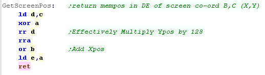
| We're going to need to be able to turn a X,Y position into a
memory address, so we know where to write to to set data... We'll
Write 'GetScreenPos' it'll take a XY position and return an address
in DE Because our screen is 256 pixels wide, and each byte is 2 pixels, To calculate a memory location we can use the formula: Addr= Ypos * 128 + Xpos Because we have no multiply command, we effect this by loading the high byte (D) with the Ypos, shift one bit into the low byte (E bit 7 - 'worth' 128)... we then add the Xpos - simple really! Because our screen base is actually going to be at address &0000 we have nothing else to do! |
 |
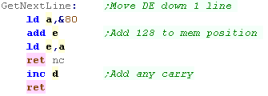
| We'll need to move down a line after each draw, but that's easy
too... again, we just add 128 bytes... If we overflow the low E register we have to INC the D register |
 |
Drawing an 8x8 sprite
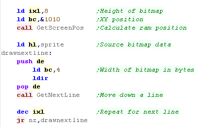
| Ok, we need some sprite data... the SAM screen is easy... each nibble is a pixel, so we just need to specify the bytes to make our 'smiley face' | 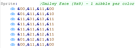 |
| Ok, we need to do some copying! we're going to load BC with the X,Y location to draw the sprite... we use GetScreenPos to calculate an address (in DE) for the destination... We load HL with the source address of the sprite... and we load IXL with a 'line counter'... the sprite has 8 lines... Now we use LDIR to copy from HL to DE... each line is 4 bytes, so we set BC to 4 When we need to move down a line, we use PUSH/POP to back up the old DE, and use GetNextLine to calculate the new line address we repeat until IXL is zero, drawing each line. |
 |
| Here is the smiley result! |  |
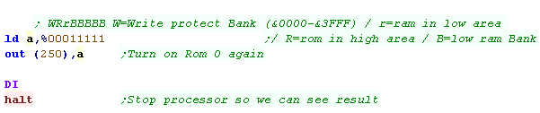
| When we're done, we may want to turn the firmware rom back on, and
reset the memory to the default, we do this with another write to
port 250... Though in this case we'll actually just HALT the cpu |
 |
Drawing a larger sprite
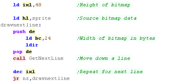
| It's pretty easy to modify this code for a bigger sprite, just
change IXL and BC... In this case we'll use a 48x48 sprite... |
 |
| And here's the result! | 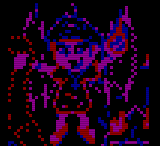 |
| Working with the SAM is both easy and hard... getting
data to the screen is easier than systems like the MSX, just write
to memory, but we have to page this huge 24k screen into ram, so we
may need to 'plan' our game around that ... For example, if you need
interrupts, then rather than using IM1 (which uses &0038
address), then why not use IM2? |
|

Setting up our screen
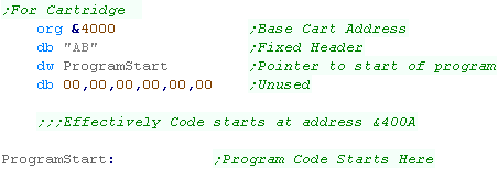
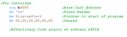
| In this example we'll make a cartridge ROM... We need to start our
rom file with a header... (If you want to know the details, see the HelloWorld example) |
 |
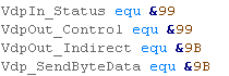
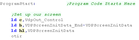
| We're going to need access to some VDP ports... To make our code clearer, we'll define 4 ports as symbols... We'll use the OUT command to access these! |
 |
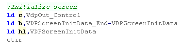
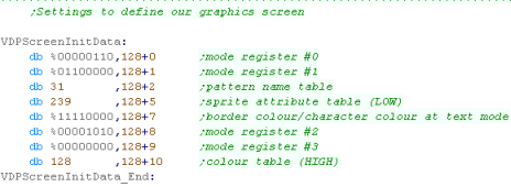
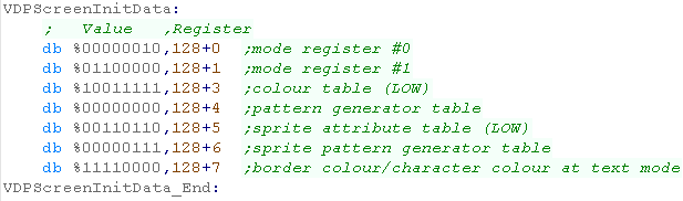
| First we need to get our graphics screen ready... We're going to define a set of bytes for the control registers... they're at VDPScreenInitData, Each is a pair, the first is a value... the second (with +128) is the register which will take that value... We're going to use the OTIR command to copy all this data to the 'VdpOut_Control' |
  |
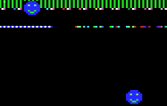
| The graphics mode will be enabled. | 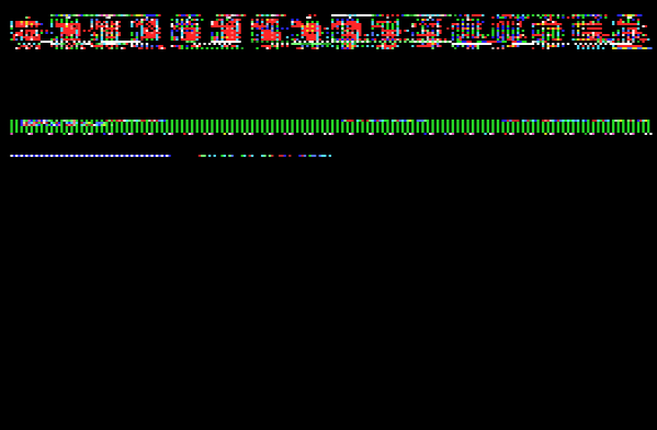 |
|
The screen will
turn to a graphics mode... But, Hey! there's some weird
corruption! Don't worry, that's just some old junk on the screen from the previous text mode, the mode change has worked fine! |
Getting a Bitmap from Z80 RAM to the VDP screen (VRAM)
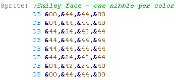
| We've got a sprite in our ROM cartridge (Z80 Ram)... but we need
to get it to the screen VRAM... In the 16 color mode, the visible screen is 256x192, but the total screen is 256x1024... all lines below 192 are hidden, but if we copy sprites there to the invisible area, we can get the VDP to fast copy them later to the visible area. Either way, the first stage is to copy from the ROM to VRAM... |
 |
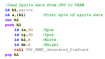
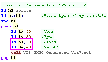
| Ok, this is going to get tricky, but we'll go through it! We need to write a series of settings and commands to the VDP via OUTS, but to make it easy, we'll use a function called 'VDP_HMMC_Generated_ViaStack' We're going to need to load the first byte of our sprite into the Accumulator IX will be the destination Xpos in pixels IY will be the destination Ypos in pixels HL is the width of the bitmap in pixels DE is the height of the bitmap in pixels |
 |
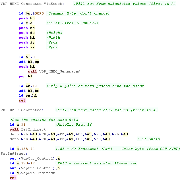
| We're going to use lots of OUTI's (Bytes &ED,A3) to send data
to the VDP port 'VdpOut_Control'... but we need the bytes to be in
ram somewhere, with HL pointing to the first byte for OUTI to
work... We'll achieve this by pushing all the values onto the stack (in ram), and use this with the OUTI... we need to use a command called 'HMMC' to do the CPU->VRAM transfer - this is command &F0 We need to set up the 'Indirect write' register - and tell it we want to start writing from 'Register 36' (DX - Dest Xpos)... you don't need to know the register numbers, but if you want to, they're all on the MSX page Sendign the data is done with 11 OUTI's .... we represent these as bytecode to make it neater Once this is all done, we'll have set up the screen area for the bitmap, and written the first pixel, now we just need to send the rest! |
 |
| We've only sent one byte so far (the one in A)... so we need to send the other pixels!, but now we can just write them to the 'VDP_SendByteData' port, and the VDP will fill the square we defined in the last stage! | 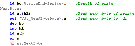 |
| Our smiley has been printed on the screen. |  |
|
We've got our
bitmap to the screen! This is a great way of transferring sprites from CPU Ram to VRAM, or for generating graphics from calculations... but it's too slow for sprites in a game... We need to use the HMMM command for sprites, copying VRAM to VRAM! |
Fast copying from VRAM to VRAM
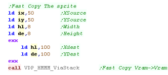
| Ok, we learned how to get data from RAM to VRAM, but that was
pretty slow, once our sprite is somewhere in VRAM, we want to be
able to copy it faster... Like last time, we're going to store the settings in our registers... this time we're going to use the shadow registers too, as we don't have enough otherwise! We use a different command this time HMMM! (Fast copy) |
 |
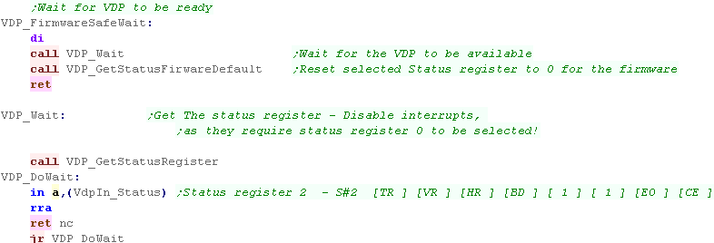
| When we're doing fast commands, we need to check if the VDP isn't
busy doing something else, we do this with
'VDP_FirmwareSafeWait'.... Why is it 'Firmware Safe'? well, the firmware interrupt handler needs register 0 to be selected, but we need to select register 2 to see if the VDP is busy, so we need to disable interrupts while we're working to be 'safe' to work with the firmware. |
 |
| The next stage is pretty much the same as last time, but this time
we're using command &D0 We need to check if the VDP is still busy with that VDP_FirmwareSafeWait command, we also need to set up more registers, this time we're starting from Register 32 (SX: StartX)... and writing 15 bytes. |
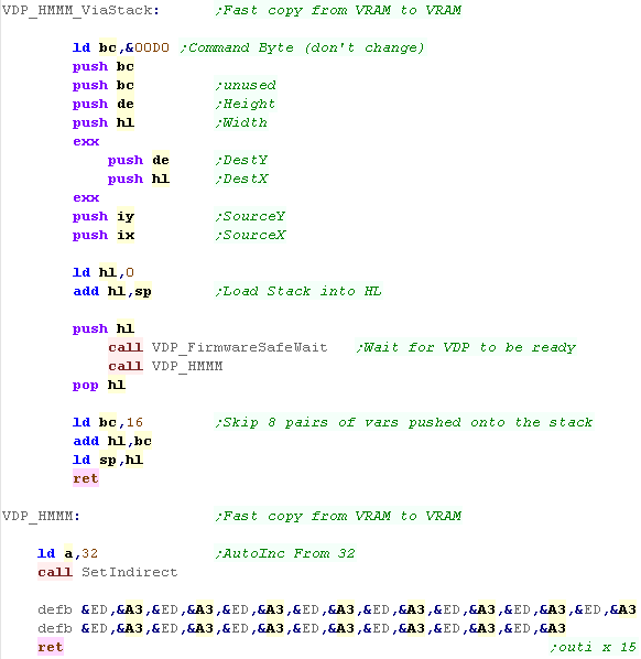 |
| We've copied the first sprite quickly, and made a second smiley! |
 |
| Remember... the VRAM
screen is 256x1024, if we store our sprites in a 'grid' offscreen,
we can copy those sprites into the visible screen as we need them! This is how ChibiAkumas worked on the MSX2 - lines 512+ were the level and character sprites (and font)... the first 512 were the two screen buffers (Screen buffer 2 must start at line 256) |
|
Working with larger sprites
| The code can really works with any sprite size, all we need to do
is change the Width and Height in the VDP commands... In this case we're using a 48x48 sprite |
 |
| You can see the results here. | 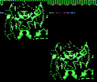 |
|
This command is
super fast and totally kicks ass! Because the VDP has it's own CPU, a large sprite will still be drawing while our CPU gets on with other work... this is why we need to check if the VDP is busy or not before sending another command. |
Setting up our screen
| We're going to create a cartridge... first we need to define a
header to do this. See the Hello World example for more details. |
 |
| We need access to the VDP (graphics) hardware... we will OUT these when we want to change hardware registers or write data. |  |
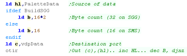
| OK, we're ready to start our program! First we need to set up our screen, we use an OTIR command, this will copy a bank of settings to the VDP... Each is a pair, the first is the new value for the register - the second is the register number (plus 128)... this will set up the tilemap screen this tutorial needs. We're ready to start our example! |
  |
| We can't set 'pixels' directly on the screen like the
spectrum, instead we define our image as a 'tile'... then define an
8x8 block of the screen to show that tile... The disadvantage is that this makes setting a pixel harder (so a 3d game vector like 'star wars' would be tricky).. but we can change the entire screen by altering 768 bytes (32x24 tilemap) so we can 'scroll' the screen quickly! |
|
Showing an 8x8 tile to screen
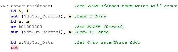
| We're going to need to define a function to select a VRAM memory
address to write to, it's pretty simple... To select the VRAM address VdpOut_Data will write to, we first write the low address (L) to the VdpOut_Control port... then we write the high address (H)... But we need to set bit 6 of the H address... this tells the VDP we want to WRITE to vram (if we didn't we'd read)... Finally we set C to VdpOut_Data... this will help us later! |
 |
||||||||||||||||
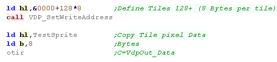
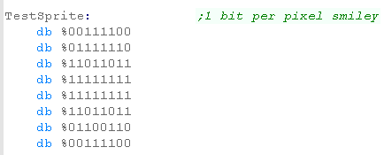
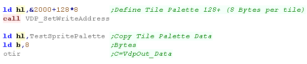
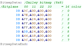
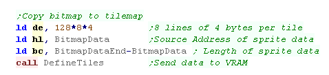
| Ok, we're going to have to define our graphic (a smiley) as a
TILE... The tile has two parts, the first is a 1bpp bitmap... we need to copy this to &0000+ (the bmp data address)... we're going to use tile 128 (to make space for a font)... and as each tile is 8 bytes tall, we load to memory &0000+128*8 We use OTIR to copy B bytes of data from HL to C (remember we set C to VdpOut_Data) with the 'SetWriteAddress' Command |
  |
||||||||||||||||
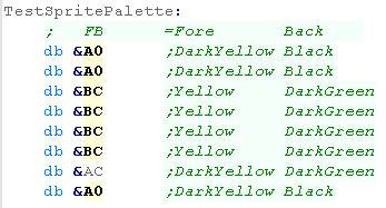
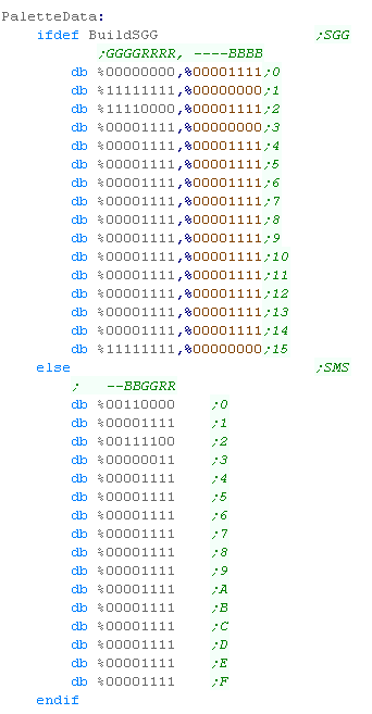
| As well as 8 bytes of bitmap data, each tile also has 8 bytes of
color data (one byte per line)... this data starts at address
&2000 This data is in a simple format, the top nibble is the foreground color, the bottom is the background color. The colors are shown below:
|
  |
||||||||||||||||
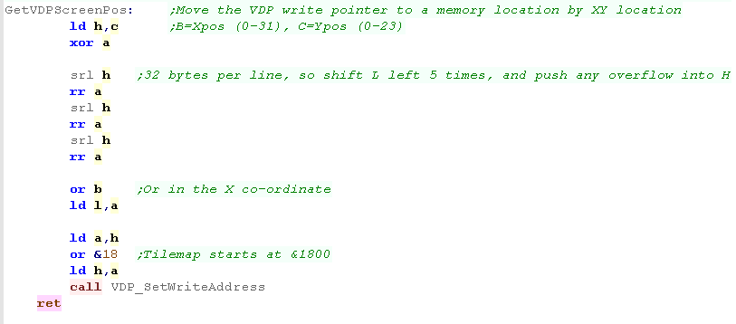
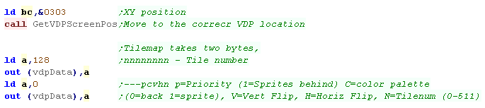
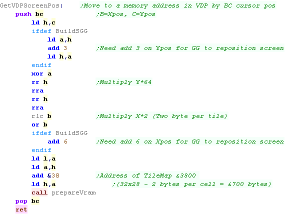
| We've defined our tile, but it's not visible on the screen! To get
it shown on the screen, we need to set the correct byte of the
Tilemap (starting at &1800 in vram) to our tile number We're going to define another function called 'GetScreenPos' - it takes an X,Y address in BC The tilemap is 32 bytes wide, so our calculation for the VRAM address of a tile is &1800+(Ypos*32)+Xpos... We calculate the address here, and use SetWriteAddress to select the VRAM Address |
 |
||||||||||||||||
| To make the tile visible, we need to use GetVDPScreenPos to set the destination address in the tilemap, then write the tilenumber (128) to that address. | 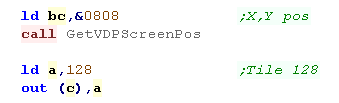 |
||||||||||||||||
| The tile will be shown to the screen! Notice there are two shades of yellow in the face, and the background in parts is black, and green in others... thanks to the tile per line color map. |
  |
|
On the Spectrum,
we only have one color attribute per 8x8 square, but on the MSX1
it's 8x1! We also have full control of the foreground and
background color (no shared BRIGHT attribute) Some MSX1 games are 'speccy ports', but this doesn't do the potential of the MSX1 tilemap justice. |
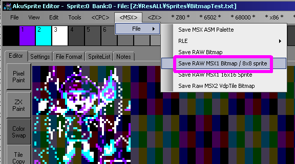
Showing a bigger sprite!
| Ok, this time we're going to show a 48x48 bitmap... we're going to
split this into 8x8 tiles... In tiles, our 48x48 pixel bitmap will be 6x6 tiles... To do this you can use my AkuSprite Editor (included in the sources.7z)... The Save Raw MSX1 Bitmap option will save in the required layout |
 |
| We need to import the binary saved by AkuSprite Editor, we also need to define a matching colormap. | 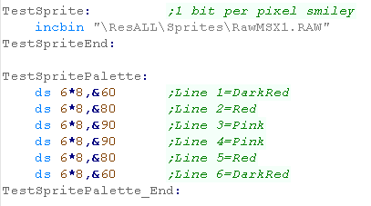 |
| 6*6*8 is 288... that's more than B can store, so we can't easily
use OUTIR to transfer the data, so we'll define our own called
OutiDE... This function will use OUTI to send the data, and use DE as the byte counter (we can't use BC as C is the destination port) |
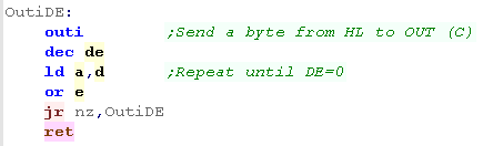 |
| We're going to use that OutiDE command to transfer our bitmap data, and palette for our tile in the same way as with the smaller tile. | 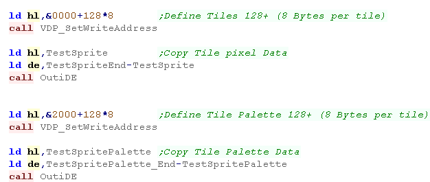 |
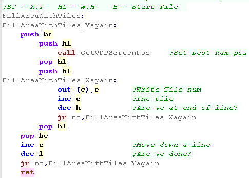
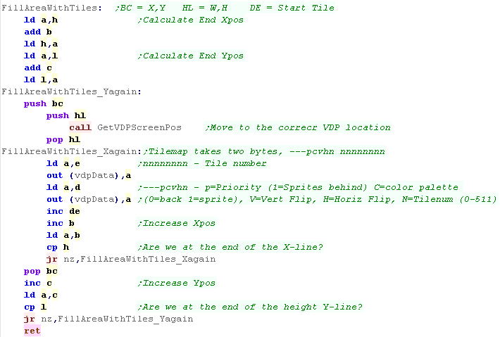
| Our 'Chibiko' image is made up of 36 tiles, we'll need some code
to set all the tiles to the correct tile numbers to show the bitmap
correctly. We'll create a function called 'FillAreaWithTiles'... it'll take an X,Y stary position (in BC), a Width and Height (in HL), and a first tile number (in E) The routine will show all the tiles to the screen |
 |
| We'll use this function to show our character to the screen. | 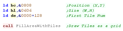 |
| The result can be seen here. | 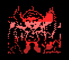 |
| We've used the
Tilemap here to simulate sprites, rather than real hardware
sprites... this saves us from the limitations of a fixed number of
sprites onscreen, but means we can only have graphics aligned to
8x8 positions... If you're just starting out, this should be enough for you, as you'll be able to do plenty with the Tilemap, and later once you're more familiar with the hardware you can move onto hardware sprites! |
|

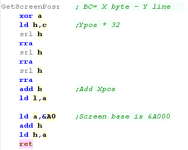
Showing an 8x8 tile to screen
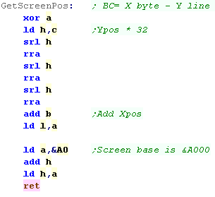
| We're going to need a function to calculate the memory address of
our destination... the screen is 32 bytes wide, and starts at
&A000 in ram, so our formula is: Address= &A000+(Ypos*32)+Xpos We achieve the *32 by loading the Ypos (C) into H, and shifting to the right 3 times into L |
 |
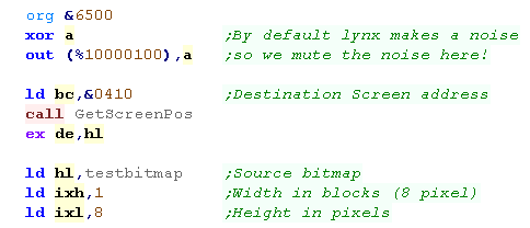
| We're going to show an 8x8 smiley face to the screen!... as each line needs a Blue,Red and Green component... we need 3 bytes per line. | 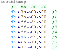 |
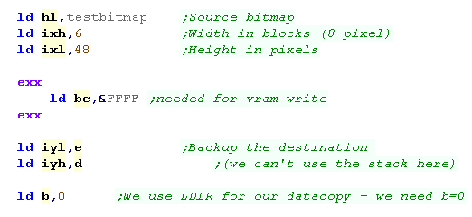
| Starting our program, we use GetScreenPos to get the Destination
screen location... we then move this into DE... Next we load the source into HL We need two registers for width and height of the sprite... we use IXH and IXL to store these |
 |
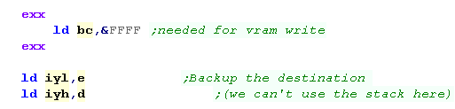
| Because we can't use the stack, we use shadow registers (HL',BC'
and DE')... EXX swaps the regular registers with these shadow
ones... we'll use them during bank switching, so we need
BC=&FFFF We need to back up DE for our processing, so we back it up into IY (IYH/IYL) We're ready to start writing graphics data! |
 |
| Lets do the Blue byte!... (at memory address &A000+) We page in the Blue/Red ram by sending &03 to port &FFFF (BC') and &28 to &xx80... We copy the byte from HL to DE with a LDI |
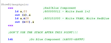 |
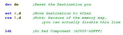
| Lets do the Red byte!... (at memory address &C000+) There's no paging, as the Red bytes are in the same bank as the blue ones... We DEC DE to reset the write position, then we set bit 6, and reset bit 5... changing &Axxx to &Cxxx Then we do another LDI |
 |
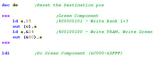
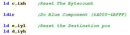
| We need to do the Green byte next (also at memory address
&C000+) it's in a different bank, so this time we send &05 to port &FFFF (BC') and &24 to &xx80... We do another LDI |
 |
| We need to add &20 (32) to our position in DE to move down a line, then we repeat for the other 7 lines | 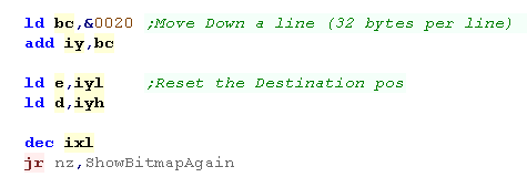 |
| We turn off drawing by sending &0 to port &FFFF (BC') and &0 to &xx80... we can now use the stack again! | 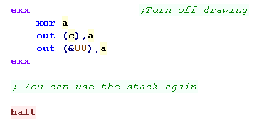 |
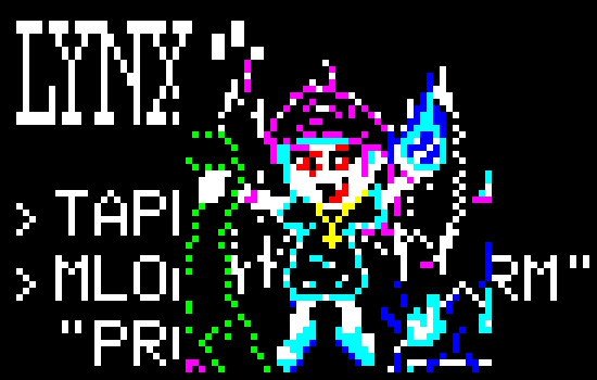
| We've finally got our smiley! |  |
Showing a bigger sprite!
 |
Lesson
S8 - Easy Sprites on the TI-83 The TI-83 isn't really a games handheld... but it can do a few simple graphics... Lets learn how to make a simple sprite onscreen! |
 |
 See
SimpleBitmap
folder
|
 |
| The TI-83
documentation use X and Y backwards! X goes down... and Y goes across the screen... the 'X and Y' in this documentation is the more typical way... X goes across - Y goes down! |
|
Showing an 8x8 tile to screen
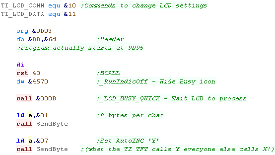
| We need to set up some stuff before we start drawing... first we
need two ports (which we access via OUT) to control the LCD - one
takes commands (&10) and the other takes data (&11) We then have the header for our file. we run a system routine (via RST 40)... the command is 'RunIndicOff) (&4570) this turns off the 'busy' icon which would otherwise appear in the top right We need to wait for the LCD to process the command, so we call &000B (LCD Busy Quick) - this command will wait for the LCD to finish we then need to send a command to the LCD - command 1 - this defines the screen as using 8 pixel wide characters We then set the Autoinc... this will make consecutive writes go across the screen (which the documentation calls the Y axis!) |
 |
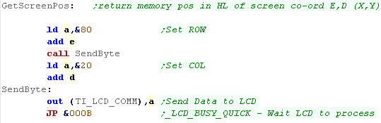
| We're going to create a 'GetScreenPos' function... this will taxe
an XY pos in DE... we have to convert these into 'Command bytes', so
we add &80 for the Ypos, and &20 for the Xpos... We'll define a function called SendByte, this will send these to the Command port , and wait for the LCD to process them |
 |
| We're defining our sprite here... it's just one byte per line. | 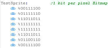 |
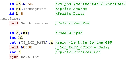
| We're going to draw our 8x8 sprite! First we load the destination pos in DE... we load the source sprite in HL, and the height in B for each line, we load in one byte from HL, and send it to the Data port of the LCD (&11)... Unfortunately we have to wait after EVERY write! As our sprite is just one byte wide, we just inc E after each write, and recalc our screen postiion, we then repeat for the next line! |
 |
| The Sprite will be shown to screen | 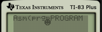 |
Showing a larger sprite to screen
| If we add an X loop, we can make the code work with wider sprites, this will allow us to draw our 48x48 sprite | 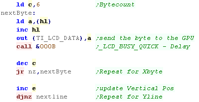 |
| Our sprite will be shown onscreen. | 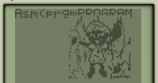 |
|
We have to do a
wait with LCD_BUSY_QUICK (&000B) after every byte written to
the screen It means we'll not have the fastest graphics, but the screen is so small it's unlikely to matter |
The Cartridge header
| We need a valid cartridge header - the one shown will work for this example... note some emulators will need a valid checksum at $&014D - VisualBoyAdvance does not. | 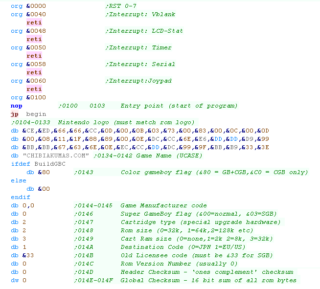 |
| There are lots of
options in the Header, but if you want to customize it, you'll
need to look into it yourself, as it's outside the scope of what
we're covering here... The example shown here should be enough for most people starting coding the gameboy. |
|
Setting up Tiles and palettes
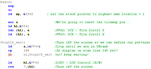
| First we're going to turn off interrupts and set up our stack. Next we'll reset the scroll of the tilemap to zero Ok, we want to define our tiles, but we need to turn the screen off first... First we wait for Vblank, by waiting for the linenumber (at &FF44) to be line 145... Then we turn the screen off by clearing bit 7 of &FF40 (LDC Control) |
 |
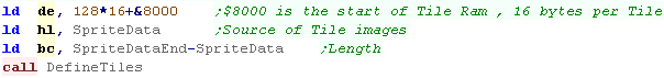
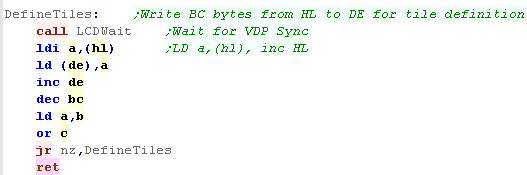
| We need to copy our tiles... we've got a 'DefineTiles' Function to
do this ... it will copy BC bytes from HL to DE... DE needs to be an address in VRAM... Tiles start at &8000 - each tile is 8 lines - 2 bytes per line - so 16 bytes... We start from tile 128 (so we can have a font from 0-127)... so we set DE to 128*16+&8000 |
 |
| Our define tiles function first checks if the LCD is busy - with
the 'LCDWait' function - we'll take a look at that in a
moment... Next it copies the data... LDIR would be perfect for this - but the GBZ80 doesn't have it! we use a set of commands to simulate a LDIR - including LDI - a special GBZ80 command that Loads from HL, then adds 1 to HL! (LoaD and Increment) |
 |
| LCD Wait will make sure we can safely write to VRAM, it checks bit 1 of &FF41 - when it's zero we can write to VRAM without problems. | 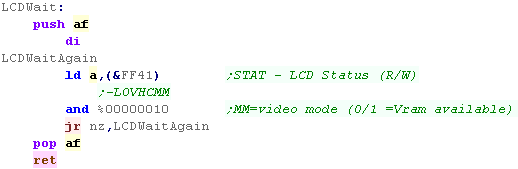 |
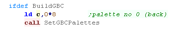
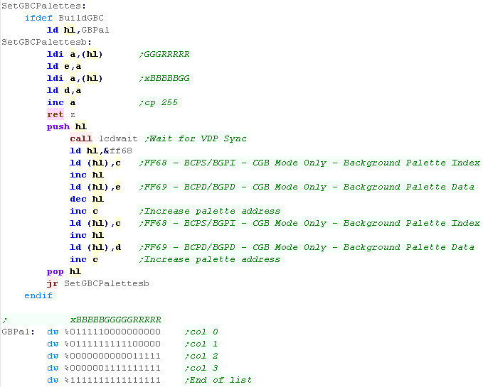
| OK, we want to set up our palette... On the Gameboy Color we're going to use a function called SegGBCPalettes... each palette is 8 bytes, we specify the palette address with C |
 |
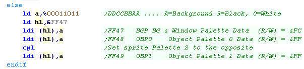
| On the Regular Gameboy, we use 2 bits for
each of the four colors to set the darkness of the color... We set the background and first sprite palette to one set of colors, then invert them for the second sprite set. |
 |
| On the Gameboy Color We set palettes with two ports... Port &FF68 selects a color 'address'... &FF69 sets that byte of the color... The colors use a 5 bit per channel color format |
 |
| We're ready to turn our screen back on - by setting bit 7 of &FF40 |  |
Setting a 8x8 tile
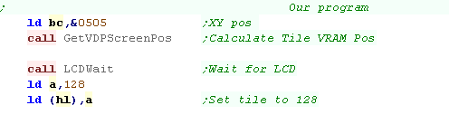
| When we want to set a visible tile, we need to write to the
correct address... we'll use GetVDPScreenPos to calculate the
address from an XY co-ordinate in (B,C) The base of the tilemap is at &9800, and the tilemap is 32 tiles wide (each tile is 1 byte), so our formula is: &9800 + (32 * Ypos)+ Xpos |
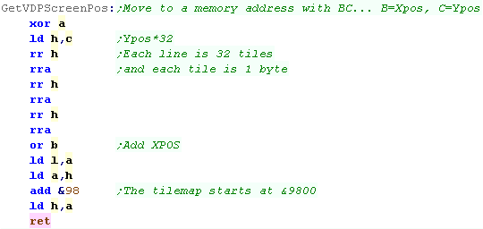 |
| We use our GetVDPScreenPos function to calculate a memory address. Now we need to check VRAM is available, so we use LCDWait again. Now we just write the tile number (128) to HL |
 |
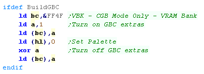
| on the Gameboy Color there's one extra step we probably want to
do. The Tilemap has an extra byte - at the same address in a different bank - this holds the palette number. We page it in by writing 1 to &FF4F... and page it out by writing 0 to the same address |
 |
| Tiles on the gameboy use 2 bitplanes per line... each bitplaine is a single bit for 8 pixels, and the two bitplanes together | 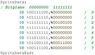 |
| Our tile will be show to the screen |  |
|
The GBC has
more options than just palette in its extra ram bank, it can also
do H/V flip, and supports an extra bit for tile number, allowing
tiles upto 512! |
Using multiple tiles to define a larger bitmap
| For this example we don't have enough registers... we'll define two bytes of RAM (which starts at &C000+) for that purpose | 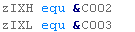 |
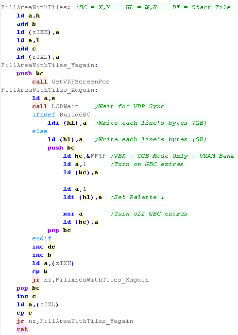
| We're going to break our image up into 8x8 chunks, and draw it onto the screen with a function called 'FillAreaWithTiles' | 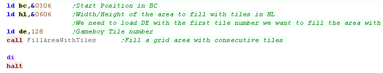 |
| Our function will use zIXH (defined above) as the end of horzontal
byte count, and zIHL is the vertical line end count We use our GetVDPScreenPos to calculate the start of the line, and start writing our bytes until the end of the line. On the Gameboy Color we also set the palette of the tile (in the extra VRAM bank)... we're using Palette 1 in this example |
 |
| The result can be seen here. |  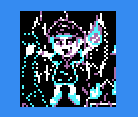 |
The Cartridge header/Footer
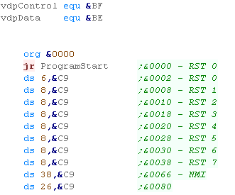
| To Start our cartridge, we
need a jump to our program code, we also need the RST and NMI
handers, but we'll set all those to RETurns We're also going to define symbols for the Control port, and Dataport of the VDP |
 |
| Our cartridge also needs a footer, this should appear at &7FF0 | 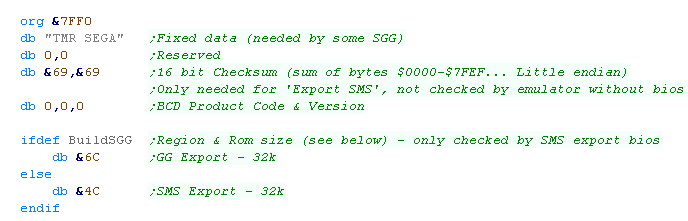 |
|
Remember!
Depending on our emulator and settings we may need a valid
Checksum, but most emulators will not mind if it's wrong. |
Setting up Screen and palettes
| When our program starts, we first need to set up a stack pointer, and set up the screen with a set of predefined screen setting... this will turn our screen on so we can use tiles. | 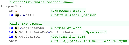 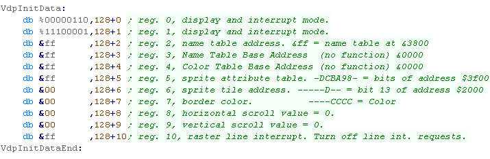 |
| We also need to define our
palette... The palette is one of the few times the SMS and GG are different - as the GG has a better palette! |
  |
Setting a 8x8 tile
| We're going to show an 8x8 tile 'smiley' to the screen... The tile is 8 lines tall, and each line has 4 bytes which uses 4 'bitplanes' (on bit of all 8 pixels per byte) |
 |
| We're going to transfer our bitmap into Tile ram using a function
called 'Define Tiles' We specify a memory address in DE - each tile is 4 bytes per line (4 bitplanes) and 8 lines... in this case our first tile is tile 128, so we set DE to 128*4*8 |
 |
| The Define Tiles function will use the PrepareVRAM function to select a memory address, then send the bytes to the VdpData port. | 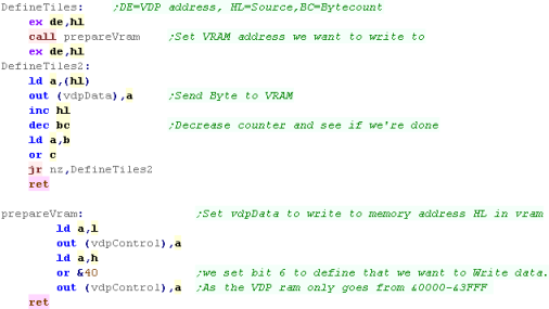 |
| If we want to set a tile, we can use the GetVDPScreenPos command
to convert an XY co-ordinate in BC to a memory address in VRAM Once we've selected the VRAM address we need to write two bytes to select the tile number, and any other options. |
 |
| We need to convert an X,Y co-ordinate into a memory address in
VRAM... the tilemap starts at &3800 - and is 32 tiles wide...
each tile is 2 bytes, so our formula is: Vram Address = &3800 + (64 * Ypos) + (2 * Xpos) We effect the multiplication with bit shifting. But, there's a catch! the GameGear does not show the full tilemap, the tilemap starts at X,Y pos (0,0), but the first visible tile is (6,3), so we add 6 to the Xpos, and 3 to the Ypos Finally we use PrepareVram, which will select the address as the next destination to write to. |
 |
| The smiley will be shown to the screen. | 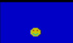 |
| We've just put a tile on the screen, for a simple
beginners game this should be enough to make something fun! Later on you'll want to progress to sprites, but since the sprite and tiles use the same 8x8 bitmap data format, you'll be able to use the same graphic! |
|
Using multiple tiles to define a larger bitmap
| If we want to show a larger graphic, we need to split it into 8x8 tiles, and use those tiles to show the image... | 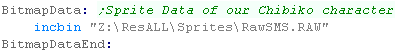 |
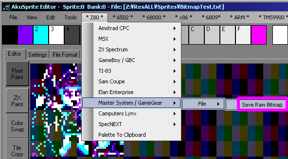
| We can export the image from my AkuSprite Editor... it will split
an image into 8x8 tiles in the same layout as the code in this
tutorial The "Save Raw Bitmap" option will save the image as valid tiles or sprites for the SMS/GG |
 |
| We're going to use a function called 'FillAreaWithTiles'... this
will use concecutive numbered tiles to draw a grid based bitmap on
our screen's tilemap. BC is the start XY Pos, HL is the Width and Height... DE is the first tile number of the image. |
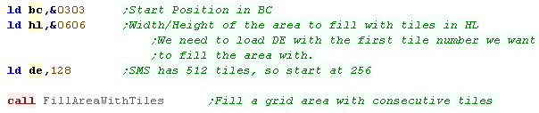 |
| We need to set a grid area with consecutive tile numbers to draw
our bitmap... the code to the right will do this... We use GetVDPScreenPos to calculate the start of a line... then write the tilenumbers from DE... INCreasing DE each time H will mark the end of the line... when we get there, we increase C and recalculate the screenpos. We repeat until we've done all the lines |
 |
| Our character will be shown to the screen! | 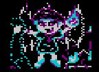 |
The Code
| We're going to need some variables for our player position... one for the Current position, and one for the previous position (so we can remove the old sprite) | 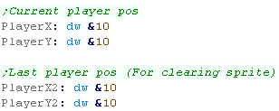 |
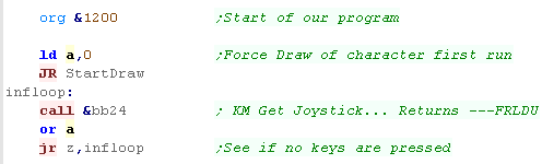
| Our code will only redraw the character when the joystick is
pressed... so the first run we need to FORCE a draw - otherwise we
wouldn't be able to see our character! The Joystick routine we're going to use is firmware function &BB24, this returns the buttons as bits in A - if all the bits are 0 then no buttons are pressed |
 |
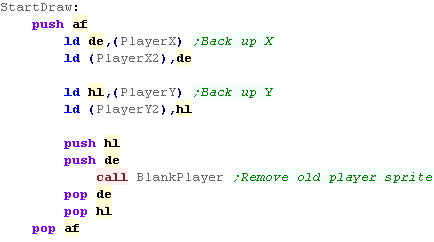
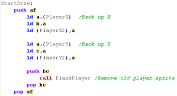
| OK, our joystick has been pressed... We need to back up the current position of the player... We're going to run our 'blank player' function... this is just our previous sprite drawing routine, with an all zero sprite |
 |
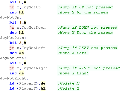
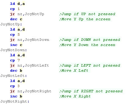
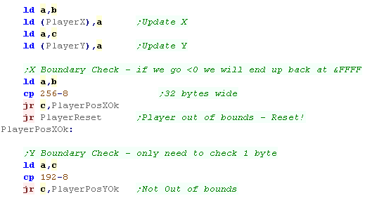
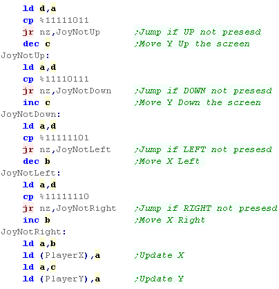
| We need to process the joystick. We need to test each bit of the value of A returned &BB24... HL is the Y axis... DE is the X axis |
 |
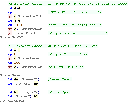
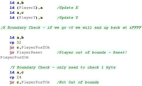
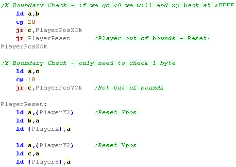
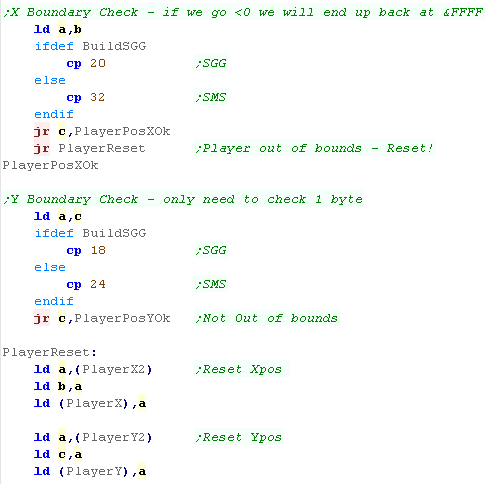
| Ok, we've moved our player, but we need to check if the sprite
will go foff the screen If the player Xpos is greater than 320-4 then it's off the screen (our character is 4 bytes wide)... also if it's below 0 that's a problem, but the value will have wrapped round to 65535, so we don't need to check this! If the player Ypos is under 8 we're over the screen (0 is the bottom of the screen - and our character is 8 lines tall)... if it's over 200 we're also over the screen... If the position fails any of these boundary checks, we need to reset the position |
 |
| We need to draw the sprite in the new position... finally we wait a bit and repeat. | 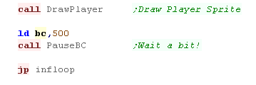 |
| We'll be able to move the sprite around! |  |
|
We've got a
movable sprite onscreen! We could use this code as a template... and add a second computer controlled player... maybe we could add a 'ball' or a 'bullet' and create some kind of battle between the two players! Really it's up to you - you've got graphics and input - so you can make whatever simple game you want! |
The Code
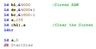
| First we're going to clear our spectrum screen, we do this with a
LDIR... we're going to set all the pixels to black. We're going to use a LDIR command to fill the &4000-&5800 range - setting the first byte to 255 so the LDIR will copy it to the rest of the range. We're then going to jump to our Draw routine! |
 |
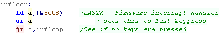
| Our keyreading routine uses the firmware, so don't put a DI in! During the interrupt handler, the firmware writes any keypress into memory address &5C08 (LASTK) We're going to read this in - if it's unchanged, then we'll wait until it does change! We skip this the first time the program runs... we load A with zero, so the key reading routines won't register a keypress |
 |
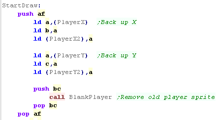
| First we need to back up the previous position of the player...
we'll need it later.. Now we remove the previous player sprite - we use the 'BlankPlayer' function - this uses our previous sprite routine to draw a 'blank' sprite over the previous player image. |
 |
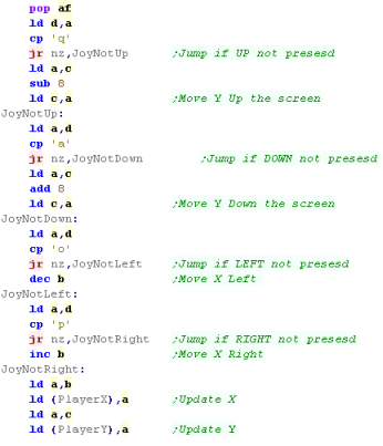
| We're going to compare the key in the Accumulator to the direction
keys.... and alter C (ypos) and B (xpos) accordingly. In each case we'll compare to our key, and 'skip' over the change to the co-ordinate if the key isn't pressed. |
 |
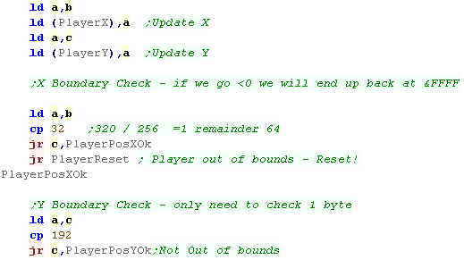
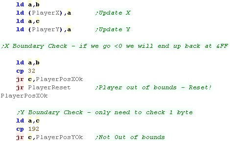
| First we'll save the new postition, and then we'll check if the
player has gone offscreen... if they have we'll need to reset the
players position... If the player XY pos goes below zero, it'll wrap around to 255... so we only need to check the top boundary.... We'll check if X (in B) goes over 32, and if Y (in C) goes over 192. |
 |
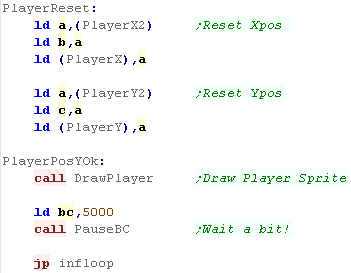
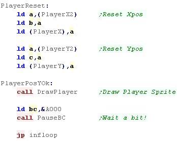
| If the player has gone out of range, we'll reset their position to the last good one from the backup. | 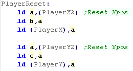 |
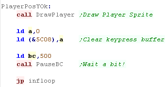
| We're done, so we draw the player sprite at the new position... Next we clear the keypress buffer, so we don't process the same keypress twice. Finally, we pause a while, and repeat the procedure. |
 |
| The result? A small character onscreen we can move around! | 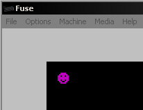 |
|
In this tutorial
we've used the Keyboard - we could of course support a 'cursor'
joystick in a similar way, or even a Kempson with some more
advanced code... This was covered in the Platform specific series - but these tutorials are aimed at beginners, so it's not something we'll look at here. |
The Code
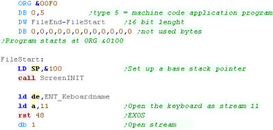
| As before, we need our program header, SP init, and screen setup, This time we have a new addition, we need to connect a stream to the keyboard to read the built in joystick... we're loading it as stream 11 |
  |
|||||||||
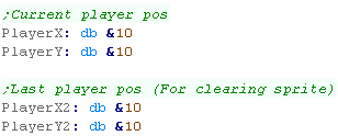
| We're going to need some variables!... we define two bytes to
store the Current XY location of our character. We'll also have a second 'backup' copy of the location. |
 |
|||||||||
| The first time we start our loop, we skip over the key reading routine (TestChar)... typically we don't redraw until a key is pressed, but the fist iteration needs to show the player no matter what! | 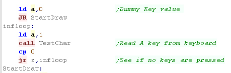 |
|||||||||
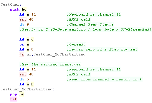
| We can read a character using EXOS call 5... this will wait for a
character - so if no keypress is waiting the program will stop... While this would be fine for this simple sample, This isn't great for a real game, as we'd probably want some CPU character to move when the player doesn't... to combat this, we use EXOS call 9 to test the stream, and tell us if a key is waiting to be read or not... if not we return 0 |
 |
|||||||||
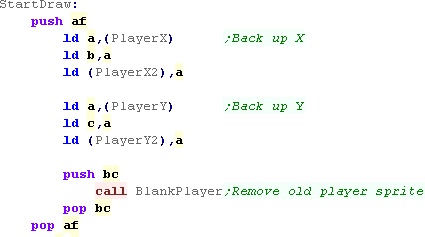
| Looking back at the start of our drawing code, we're going to back
up the current player position... Next we'll Blank the old sprite position with the 'BlankPlayer' function - this wipes the old sprite off the screen, using the bitmap routine we wrote before. |
 |
|||||||||
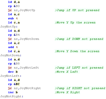
| We're now going to compare the keypress we read in, and alter the
XY position in BC accordingly... The internal joystick uses special keypresses... we check for these, and skip over the code to change the player position if the key is not pressed The UDLR keypresses are as follows:
|
 |
|||||||||
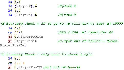
| We've read in the cursor changes, so we save the new cursor
position. Now we need to compare the new position and see if the player has gone off the screen... the top left corner of the screen is 0,0... and our positions use a single byte... this means if the player goes off the top or left hand side of the screen the position will 'wrap' back to 255 (as a 1 byte value cannot be negative)... Therefore we only need to compare against the top boundary... 80 bytes wide, and 200 lines tall - minus our 2 byte, 8 line tall sprite |
 |
|||||||||
| If the player has gone offscreen, then we need to reset the
position from the backup we took. We finally draw the new position of the player sprite, pause a moment and repeat. |
 |
|||||||||
| We will be able to control our smiley with the 'keyboard' joystick! | 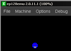 |
|
We've only used
the keyboard Joystick... If you want to use the 'real' joysticks
you'll need to use the &B5 and &B6 ports... take a look Here for more info! |
 |
Lesson
S14 - Key Reading on the Sam Coupe We made our bitmap example before - lets now extend it to add key reading to move the bitmap around the screen. |
|
SAM_Joystick.asm
|
|
The Code
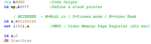
| Our code starts with our SP definition... next we need to select a
bank for our screen memory - we're using banks 14/15 for the
screen... these are the top two banks of a 256k system. We're now going to skip over the keyboard routine to start the first draw even though a key hasn't been pressed. |
 |
| We're going to need an X and Y byte to remember the position of
our player, We'll also have a backup, which we'll need for some purposes. |
 |
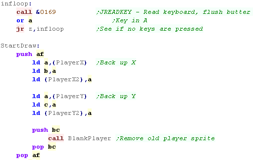
| We're going to use firmware function &0169 which will return a
key in A... we'll wait until we get one... The start of our drawing loop will backup X and Y for later, it will also run a 'BlankPlayer' routine... This is a modified version of our previous sprite routine which will write an 'empty' sprite to clear the old position of the player |
 |
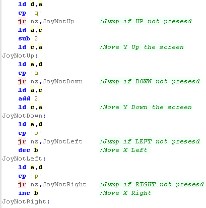
| We're now going to compare A (containing our keypress) with our
direction keys... if a key ISNT pressed we'll skip over the code
that would move the player in that direction... We repeat for the keys QAOP for the directions UDLR |
 |
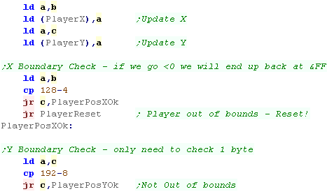
| We're going to update the stored XY variables with the new
position... then we'll check if the players went over the
'boundaries'... The top left corner is 0,0... our XY values are a single register, and if we go below zero, we wrap around to 255, therefore, we don't need to check the bottom constraint. |
 |
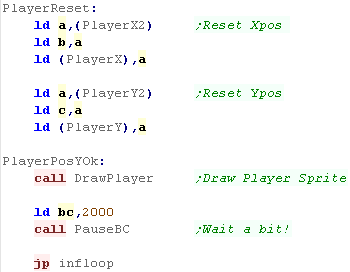
| If the player is out of the boundaries, we'll reset the position
from the backup... Finally, we'll draw the player in the new position.... pause a moment and repeat the procedure |
 |
| Our player smiley will be movable with the QAOP Keys. |  |
| The Sam Coupe can
use joysticks which will use number keys... Joystick 1 uses 6-0...
Joystick 2 use 1-5. You'll just need to reconfigure the direction keys if you want to use one of these joysticks |
|
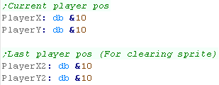
| We need to define 4 byes of RAM for our player position... a pair for the current XY position... and a pair for the previous position | 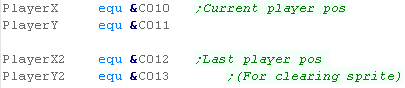 |
|||||||||||
| When our screen is set up (the same way in the bitmap tutorial), we need to reset our player position... then we skip over the key reading routine to the drawing routine. | 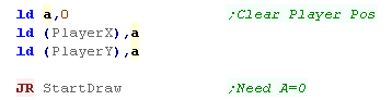 |
|||||||||||
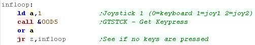
| We're going to use firmware function &00D5 to read the
joystick... this function uses A - if A=0 it will read cursors, 1 or
2 reads joystick 1 or 2 respectively We only read the joystick in this example, but there is also a function to read fire buttons We use this to read in the controls, and wait for a key to be pressed
|
 |
|||||||||||
| The start of our loop first backs up the current position of the
player, then it uses a function known as 'BlankPlayer' BlankPlayer will use the sprite routines to remove the previous sprite. |
|
|||||||||||
| It's time to move our player based on the keypresses... BC
contains the XY position of our player. We check each direction, and if the direction is not pressed, we skip over the code to change the register, This will move the character Up, Down, Left or Right. |
 |
|||||||||||
| We need to make sure our character doesn't go offscreen... Our top-left position is 0,0 - if we go below zero, the byte will wrap around back to 255 - therefore we only need to check if the X position goes over 32, or the Y position goes over 24 |
 |
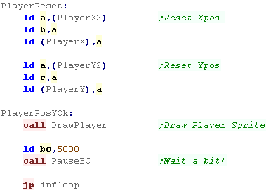
|||||||||||
| If the player has gone offscreen, we'll use 'PlayerReset' to
restore the old position. Whatever happens we redraw the new position of the character, wait a moment and repeat. |
 |
|||||||||||
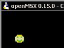
| The sprite will be shown on screen... There are two versions of this program, one for MSX1 and one for MSX2 |
  |
|
The example
here only supports UDLR... you really probably want diagonal
support as well... but you'll have to code that yourself. |
The Code
| We need to define some bytes of ram to store our variables... we store the current XY position in one pair, and the previous XY position in the other | 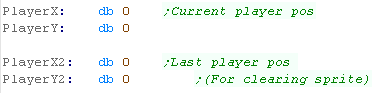 |
|||||||||||||||||||||||||||||||||||||||||||||||||||||||||||||||||||||||||||||||||||||||||||||||||||
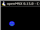
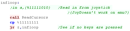
| Starting our program, we need to skip over the key-reading routine on the first run, this is because the reading routine will loop untill a key is pressed, and we need to show the first sprite to the screen. | 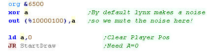 |
|||||||||||||||||||||||||||||||||||||||||||||||||||||||||||||||||||||||||||||||||||||||||||||||||||
| We're going to use a 'ReadCursors' function to read in the keys of
the Lynx - the Lynx actually had joystick ports, but it seems our
emulator doesn't support them!? We wait for a key to be pressed before we proceed |
 |
|||||||||||||||||||||||||||||||||||||||||||||||||||||||||||||||||||||||||||||||||||||||||||||||||||
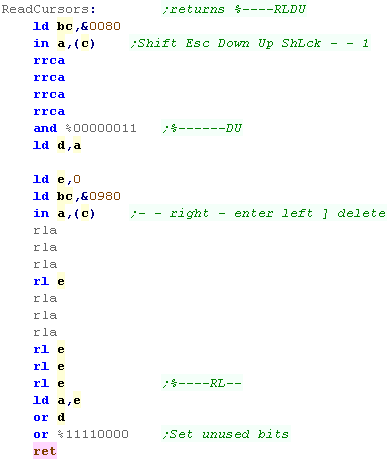
| We're going to read in the Cursors... we want to read in from two
ports, and then shift the bits of the cursors into the layout
%----RLDU The port we read in from defines the row of the matrix we end up reading from:
|
 |
|||||||||||||||||||||||||||||||||||||||||||||||||||||||||||||||||||||||||||||||||||||||||||||||||||
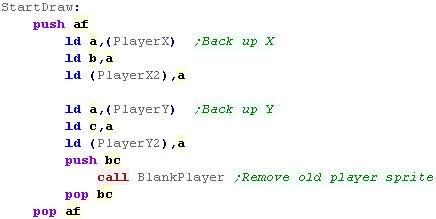
| First we're going to back up the XY position of the player - we'll
need it later to restore the player position if they go offscreen. Next we remove the current sprite... we do this with a function called 'BlankPlayer' - it will use an 'empty' sprite with the bitmap routine we saw in the bitmap example. |
 |
|||||||||||||||||||||||||||||||||||||||||||||||||||||||||||||||||||||||||||||||||||||||||||||||||||
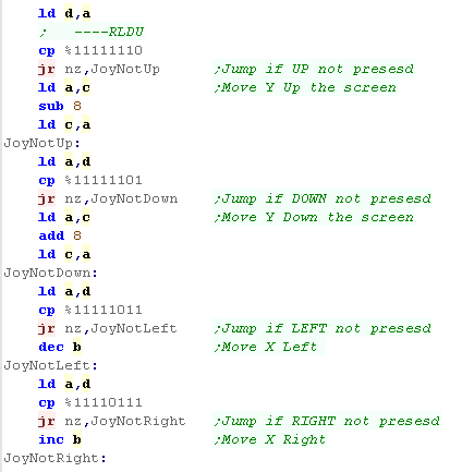
| We've got the XY pos in BC... we need to test each button (which
will be bit zero in D) If a button is pressed we need to Add/Subtract from B or C... We do this by testing each button and skipping over the 'change' commands. |
 |
|||||||||||||||||||||||||||||||||||||||||||||||||||||||||||||||||||||||||||||||||||||||||||||||||||
| We've updated the XY position, so we store it in the variables for
our player. Next we need to check if the player is still onscreen... the screen is 32 bytes wide - and 200 lines tall (or so)... As the top left corner of the screen is 0,0, and we use one byte to store our X and Y position, if we go off the top, or left hand side of the screen, we'll wrap round back to 255, Therefore we only need to check the top boundaries of 32 and 192 |
 |
|||||||||||||||||||||||||||||||||||||||||||||||||||||||||||||||||||||||||||||||||||||||||||||||||||
| Finally we update the X/Y Player position and update the player
sprite position |
 |
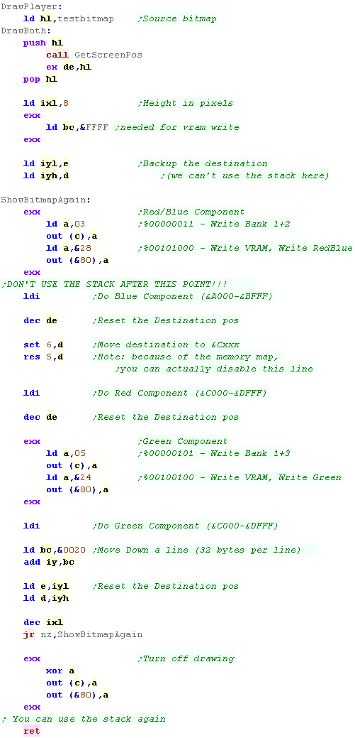
Sprite Drawing
| We're drawing an 8x8 smiley on the screen, Each line of the sprite has 3 bitplanes | 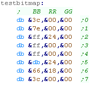 |
| We need a function to calculate the address of the first bitplane. The blue bitplane is at &A000+ The red bitplane is at &C000+ The green bitplane is at &C000+ (in a different ram bank) |
 |
| We need to page in the VRAM bank, we do this with ports (&FF)
and port (&80), when we do this, we can no longer use the stack,
as writes to ram would end up on the screen. we use LDI to transfer bytes from our sprite to the screen. We page in the first bank, and transfer the blue byte. We then set bit 6, and reset bit 5... this shifts the VRAM address from &A000 to &C000 We then transfer the red bitplane. We then page in the second bank, and transfer the green byte. |
 |

Getting started & Turning on the screen
| The Spectrum NEXT cpu has some extra opcodes for setting it's
registers, We'll define a couple of Macros to help us out. These registers control many of the new features of the NEXT |
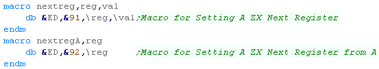 |
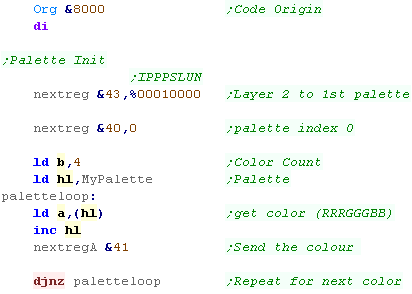
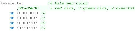
| First we need to initialize the palette... We need to tell Layer 2 what palette to use with NEXT register &43 Next we select the first palette entry with register &40... We send the palette bytes to register &41 In this example we're using 1 byte per palette entry. it uses 3 red bits, 3 green bits, and 2 blue bits. |
  |
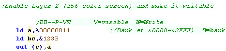
| Next we turn on the screen. Layer 2 is controlled by port &123B, the bottom 2 bits select visibility and enable "Write through" Layer 2 is a 256x192 @ 256 color screen it's 48k in total... one option for writing to this is to allow writes to the &0000-&3FFF ROM area to screen - this doesn't affect the ROM, but it means we have to split the 48k into 3 banks - each is 1/3rd of the screen (starting at the top) |
 |
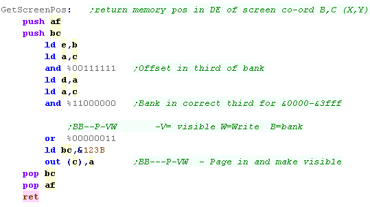
Calculating Screen Positions
| The Layer 2 screen is a simple format... 8bpp (one byte per pixel)
256 bytes wide, 192 lines tall. The only problem is that we need to bank in the correct 1/3rd of the screen so we can write to the screen. We mask out the top two bits of the Ypos to select the bank number, and out to &123B to select the bank (with the bottom two bits set, to make the screen visible and writable) |
 |
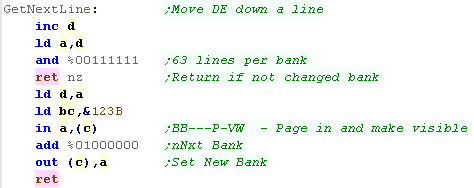
| Moving down a line is also pretty easy, We INC the top byte of our screen address However we need to check if we've reached line 64 - if we have we need to page in the next bank, and reset the top byte to zero. |
 |
Drawing an 8x8 Bitmap
| We're going to define a bitmap, it's using 1 byte per pixel, so it's easy to 'draw' a bitmap in raw bytes | 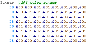 |
| We use GetScreenPos to get the starting position of our sprite. We use LDIR to copy each line of the sprite, then we use GetNextLine to move down a line and repeat |
 |
| Here is the sprite! | 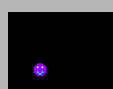 |
Drawing a larger bitmap
| We can include a larger sprite as a file | 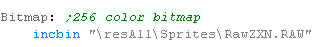 |
| We can modify the previous example for the new size. This sprite is 48 x 48 |
 |
| Here is the sprite |  |
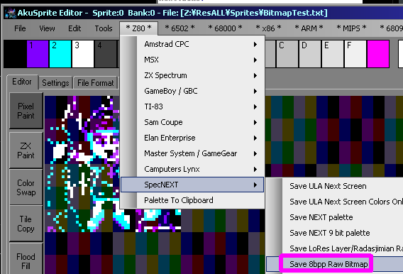
| You can create a valid sprite file with AkuSprite
Editor, Use Save 8bpp raw bitmap from the Z80->SpecNext menu |
 |
| Here we've looked at bitmaps, but the Spectrum Next
also supports Tilemap
and Hardware sprites! Depending on your game, these may be more useful. |
|
Direct Hardware Keyreader
| We're going to use a direct hardware reader this time. We select a row of the keyboard using port &FE... the 0 bit in B will select a line The byte we read in from the port. Each bit of that byte will contain the keys for that line - a bit 1 is an 'unpressed key'... a bit 0 is a 'pressed' key We shift the bits of the keys we actually want (QAOP Space Enter) into H |
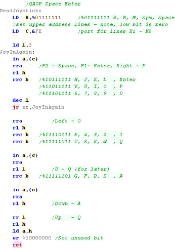 |
|
Want to learn
more about keyreading on the spectrum? Check out this
tutorial here. |
The Code
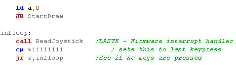
| We're using our new keyreading routine, which works without the
firmware We skip this the first time the program runs... we load A with zero, so the key reading routines won't register a keypress |
 |
| First we need to back up the previous position of the player...
we'll need it later.. Now we remove the previous player sprite - we use the 'BlankPlayer' function - this uses our previous sprite routine to draw a 'blank' sprite over the previous player image. |
|
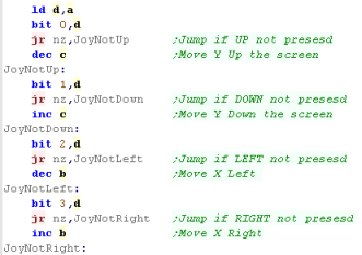
| We're going to test the bits of the returned key directions In each case we'll test each bit %--FFRLDU, and 'skip' over the change to the co-ordinate if the key isn't pressed. |
 |
| First we'll save the new postition, and then we'll check if the
player has gone offscreen... if they have we'll need to reset the
players position... If the player XY pos goes below zero, it'll wrap around to 255... so we only need to check the top boundary.... We'll check if X (in B) goes over 256-8, and if Y (in C) goes over 192-8. |
 |
| If the player has gone out of range, we'll reset their position to the last good one from the backup. | |
| We're done, so we draw the player sprite at the new position... Finally, we pause a while, and repeat the procedure. |
|
| The result? A small character onscreen we can move around! |  |
  |
Lesson
S19 - Joypad reading on the Gameboy and Gameboy Color We learned how to get a smiley on the screen before... this time lets get it moving! |
|
GB_Joystick.asm
|
|
Joypad reading
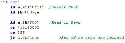
| Joypad reading is all done with
memory address &FF00 Only Bits 0-3 in this address contain the state of the buttons, we first need to select which half of the joystick we want to read. If we write %11101111 to &FF00 (Bit 4 is zero) ... we will select the diirection controls... and the next read from &FF00 will get Down, Up, Left, Right in bits 0-3 If we write %11011111 to &FF00 (Bit 5 is zero) ... we will select the button controls... and the next read from &FF00 will get Start, Select, Button B, Button A in bits 0-3 |
|
||||||||||||||||||||||||||||||||||||
The Code
| We're going to need some variables for our player position... one for the Current position, and one for the previous position (so we can remove the old sprite) | 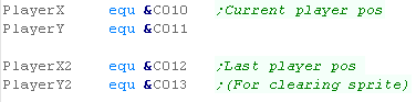 |
| Our code will only redraw the character when the joystick is pressed... so the first run we need to FORCE a draw - otherwise we wouldn't be able to see our character! | 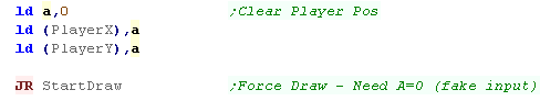 |
| We need to clear bit 4 and write to &FF00 - this selects the
direction pad when we read back... We then read in the low 4 bits from &FF00 |
 |
| OK, our joystick has been pressed... We need to back up the current position of the player... We're going to run our 'blank player' function... this is just our previous sprite drawing routine, with an all zero sprite |
|
| We need to process the joystick. We need to test each bit of the value of A returned by the joystick reading... C is the Y axis... B is the X axis |
 |
| Ok, we've moved our player, but we need to check if the sprite
will go foff the screen If the player Xpos is greater than 19 then it's off the screen ... also if it's below 0 that's a problem, but the value will have wrapped round to 255, so we don't need to check this! If the player Ypos is over 17 we're over the bottom of the screen. If the position fails any of these boundary checks, we need to reset the position |
 |
| We need to draw the sprite in the new position... finally we wait a bit and repeat. | 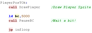 |
| We'll be able to move the sprite around! |  |
|
We've got a
movable sprite onscreen! We could use this code as a template... and add a second computer controlled player... maybe we could add a 'ball' or a 'bullet' and create some kind of battle between the two players! Really it's up to you - you've got graphics and input - so you can make whatever simple game you want! |
  |
Lesson
S20 - Easy Joypad reading on the Sega Mastersystem or GameGear Lets extend our previous smiley sprite example, and move the sprite around the screen with the joypad. |
|
See
SimpleBitmap
folder
|
|
Joypad reading
| The GameGear and Master System use 3
ports in total, but there are differences! The Gamegear has an extra button! 'Start' accessible from bit 7 of Port &00... The Gamegear does not have any player 2 controls The Mastersystem has no start button, but it does have a second player paddle! The 'Pause button' on the console causes a NMI call to address & note:Button TH has no use on the normal SMS gamepads, so is not used in these examples. |
|
|
|
The Code
| We're going to need some variables for our player position... one for the Current position, and one for the previous position (so we can remove the old sprite) | |
| Our code will only redraw the character when the joystick is pressed... so the first run we need to FORCE a draw - otherwise we wouldn't be able to see our character! | |
| To read the first joystick we just read a byte from port &DC | 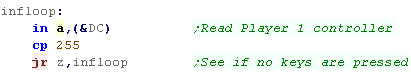 |
| OK, our joystick has been pressed... We need to back up the current position of the player... We're going to run our 'blank player' function... this is just our previous sprite drawing routine, with an all zero sprite |
|
| We need to process the joystick. We need to test each bit of the value of A returned by the joystick reading... C is the Y axis... B is the X axis |
|
| Ok, we've moved our player, but we need to check if the sprite
will go foff the screen If the player Xpos is greater than 31 then it's off the screen ... also if it's below 0 that's a problem, but the value will have wrapped round to 255, so we don't need to check this! If the player Ypos is over 23 we're over the bottom of the screen. If the position fails any of these boundary checks, we need to reset the position. The gamegear has a smaller screen (20x18) So we use different cropping settings |
 |
| We need to draw the sprite in the new position... finally we wait a bit and repeat. | |
| We'll be able to move the sprite around! |  |
|
We've got a
movable sprite onscreen! We could use this code as a template... and add a second computer controlled player... maybe we could add a 'ball' or a 'bullet' and create some kind of battle between the two players! Really it's up to you - you've got graphics and input - so you can make whatever simple game you want! |
| View Options |
| Default Dark |
| Simple (Hide this menu) |
| Print Mode (white background) |
| Top Menu |
| ***Main Menu*** |
| Youtube channel |
| Patreon |
| Introduction to Assembly (Basics for absolute beginners) |
| Amazon Affiliate Link |
| AkuSprite Editor |
| ChibiTracker |
| Dec/Bin/Hex/Oct/Ascii Table |
| Alt Tech |
| Archive.org |
| Bitchute |
| Odysee |
| Rumble |
| DailyMotion |
| Please note: I wlll upload more content to these alt platforms based on the views they bring in |
| 68000 Content |
| ***68000 Tutorial List*** |
Learn 68000 Assembly  |
| Hello World Series |
| Platform Specific Series |
| Simple Samples |
| Grime 68000 |
| 68000 Downloads |
| 68000 Cheatsheet |
| Sources.7z |
| DevTools kit |
| 68000 Platforms |
| Amiga 500 |
| Atari ST |
| Neo Geo |
| Sega Genesis / Mega Drive |
| Sinclair QL |
| X68000 (Sharp x68k) |
| 8086 Content |
| Learn 8086 Assembly |
| Platform Specific Series |
| Hello World Series |
| Simple Samples |
| 8086 Downloads |
| 8086 Cheatsheet |
| Sources.7z |
| DevTools kit |
| 8086 Platforms |
| Wonderswan |
| MsDos |
| ARM Content |
| Learn ARM Assembly |
| Learn ARM Thumb Assembly |
| Platform Specific Series |
| Hello World |
| Simple Samples |
| ARM Downloads |
| ARM Cheatsheet |
| Sources.7z |
| DevTools kit |
| ARM Platforms |
| Gameboy Advance |
| Nintendo DS |
| Risc Os |
| Risc-V Content |
| Learn Risc-V Assembly |
| Risc-V Downloads |
| Risc-V Cheatsheet |
| Sources.7z |
| DevTools kit |
| MIPS Content |
| Learn Risc-V Assembly |
| Platform Specific Series |
| Hello World |
| Simple Samples |
| MIPS Downloads |
| MIPS Cheatsheet |
| Sources.7z |
| DevTools kit |
| MIPS Platforms |
| Playstation |
| N64 |
| PDP-11 Content |
| Learn PDP-11 Assembly |
| Platform Specific Series |
| Simple Samples |
| PDP-11 Downloads |
| PDP-11 Cheatsheet |
| Sources.7z |
| DevTools kit |
| PDP-11 Platforms |
| PDP-11 |
| UKNC |
| TMS9900 Content |
| Learn TMS9900 Assembly |
| Platform Specific Series |
| Hello World |
| TMS9900 Downloads |
| TMS9900 Cheatsheet |
| Sources.7z |
| DevTools kit |
| TMS9900 Platforms |
| Ti 99 |
| 6809 Content |
| Learn 6809 Assembly |
| Learn 6309 Assembly |
| Platform Specific Series |
| Hello World Series |
| Simple Samples |
| 6809 Downloads |
| 6809/6309 Cheatsheet |
| Sources.7z |
| DevTools kit |
| 6809 Platforms |
| Dragon 32/Tandy Coco |
| Fujitsu FM7 |
| TRS-80 Coco 3 |
| Vectrex |
| 65816 Content |
| Learn 65816 Assembly |
| Hello World |
| Simple Samples |
| 65816 Downloads |
| 65816 Cheatsheet |
| Sources.7z |
| DevTools kit |
| 65816 Platforms |
| SNES |
| eZ80 Content |
| Learn eZ80 Assembly |
| Platform Specific Series |
| eZ80 Downloads |
| eZ80 Cheatsheet |
| Sources.7z |
| DevTools kit |
| eZ80 Platforms |
| Ti84 PCE |
| IBM370 Content |
| Learn IBM370 Assembly |
| Simple Samples |
| IBM370 Downloads |
| IBM370 Cheatsheet |
| Sources.7z |
| DevTools kit |
| Super-H Content |
| Learn SH2 Assembly |
| Hello World Series |
| Simple Samples |
| SH2 Downloads |
| SH2 Cheatsheet |
| Sources.7z |
| DevTools kit |
| SH2 Platforms |
| 32x |
| Saturn |
| PowerPC Content |
| Learn PowerPC Assembly |
| Hello World Series |
| Simple Samples |
| PowerPC Downloads |
| PowerPC Cheatsheet |
| Sources.7z |
| DevTools kit |
| PowerPC Platforms |
| Gamecube |
| Work in Progress |
| ChibiAndroids |
| Misc bits |
| Ruby programming |
Buy my Assembly programming book
on Amazon in Print or Kindle!


Available worldwide!
Search 'ChibiAkumas' on
your local Amazon website!
Click here for more info!


Buy my Assembly programming book
on Amazon in Print or Kindle!
Available worldwide!
Search 'ChibiAkumas' on
your local Amazon website!
Click here for more info!
Buy my Assembly programming book
on Amazon in Print or Kindle!
Available worldwide!
Search 'ChibiAkumas' on
your local Amazon website!
Click here for more info!