| the MSX2 VDP uses various
registers to control it's settings... we operate these via OUT
calls... It also has some status registers, which we will need to check to see if our jobs are finished, as it can only do one task at a time! The table here is just a summary for quick reference. If you want to know all the details, you should download the v9938 documentation here or check out this tutorial Registers The VDP uses registers numbered 0-46... To Set a register, first send the value to put in the register to the control port, then send the register number +128 to the control port. EG lets set Reg 15 to 2... ld a,2 out (&99),a ld a,15+128 out (&99),a There are some special registers R#15 sets the Status register R#17 sets the indirect register... this allows us to set a range of registers in one go via port &9B... this allows us to use a sequence of OUTI commands to set registers, when we're giving the VDP jobs to do we usually need to set 32-46... so we set the indirect register to 32... then OUTI away! Commands We only need to use 3 commands today... HMMV is a flood fill command, it clears the screen quickly and gets pixels to screen faster than any other command HMMC is used to copy byte data from the normal Z80 memory to the VDP ram - we use this to create our tiles! - it's the slowest of our commands HMMM this is our workhorse... once our tiles are in VRAM, it gets them on our screen.. it's a bit slower than HMMV, but much much faster than HMMC We don't use it today, but and alternative to HMMM is LMMM - it does the same job, but can do transparency... its slower than HMMM, but is the best way to do sprites with transparent backgrounds. Status Registers We have to check CE to see if it's 0 - if it isn't the VDP is busy and we have to wait as it's doing another command, we need to select S#2 If it's busy the VDP can still do direct memory access while it's busy though, and ChibiAkumas uses this to draw the background gradient with the Z80 WHILE the VDP is blitting the mountain tiles, and flood filling the black areas of the background! The default Interrupt handler relies on S#0 selected... this is because the MSX will fire interrupts indefinitely until S#0 is read... therefore we MUST disable interrupts until S#0 is selected again, or write our own interrupt handler! |
Commands Here are the commands we'll be looking at today!
Registers Here are the main registers we'll be looking at today for our commands!
Status Registers Here are the Status Registers we need:
Special Register Selection We select our Status register, and the AutoIncrement Indirect port (&9B) with the registers below:
|
|
 |
The bad
news is this is just the beginning... check out the MSX
page, or get the V9938 manual to see the full details! The good news is you can just use the code provided in these tutorials to do the work for you, and the V9990 version will work exactly the same for the V9K accelerator |
MSX2 VDP commands
We need a few VDP commands to do todays work, Lets take a look!
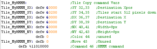
| When we call our commands
today, we need to pass them the address of a set of
definitions our functions will push these values into the
registers. Here is an example of one of the larger commands that uses many of the registers... some (Like HMMV / Fill) don't need SX and SY and remember, if you use my functions, you can support the V9990 with the same byte definitions as this - where needed, the V9K code will convert them to the format needed for the V9990! |
 |
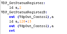
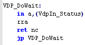
| Before we can do any commands,
we need to check if the VDP is busy... to do this we need to
select status register 2! (S#2)... the selected status
register is defined by register R#15 We do this by sending the number of the Status Register (2 for S#2) we want to select to the control port (&99) Now we need to tell the VDP the register we want to change (15 for R#15)... we have to add 128 to the number of the register we want to change Now we need to check if CE (bit 0) is 0 - if it's 1 we need to wait some more... we read in the Status register from the control port (&99) We use RRA to pop off Bit 0, if it's zero (No Carry) we don't need to wait any more, if it's 1, we need to keep waiting... Remember, We must disable interrupts while we're doing this! - once we're done, we need to set the Selected Status Register to 0 |
  |
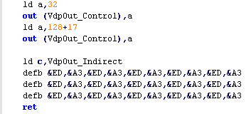
| We're going to write the
contents of our definitions to the registers (Shown in
Tile_MyHMMM above), we want to fill them all one after
another, and we can do this with the Indirect register We're going to use the Indirect register port (&9B)... to select the register we want to start filling, we set R#17 to 32 (SY)... each OUTI will then fill registers R#32, R#33, R#34 and so on... in this example we want to do 15 OUTI's... which will make our code a bit messy, so we specify them as bytecode (&ED,&A3) is the bytecode for an OUTI command! The code to the right does HMMM and HMMC, but HMMV is basically the same, just starting from R#36, and with fewer OUTI commands - because we don't need SX and SY... the important thing is the command that goes into R#46 ... and that's in our Tile_HMMM definition as the last byte... It DOES need to be the last byte - as the VDP starts processing |
 |
| We
can even use the indirect register as a fixed register
pointer... If we set R#17 to 32+128 then all our OUT commands to port &9B will go to register R#32 ... Adding 128 to the register number we write to R#17 does the job of telling the VDP not to increment! |
 |
Using the VDP commands to get stuff done!
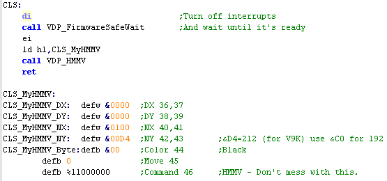
| First let's do the most basic thing, and Clear the Screen! Before we can do anything else, we need to make sure the VDP isn't busy doing other things, we'll use VDP_FirmwareSafeWait... this function will loop until the VDP is ready, and will keep the status register correct so the interrupt handler doesn't have problems. The best command for this is HMMV... it fills a square area with a single byte... we'll define a set of HMMV bytes in 'CLS_MyHMMV We'll set DX and DY to 0 - to select the top left corner of the screen... then we'll set NX to 256 and NY to 192 (the size of the screen) We want to fill the screen with color 0, so we set the Byte (R#44) to &00 We can then use VDP_HMMV which will push our CLS_MyHMMV definitions into the registers and start the job! |
 |
| Once again, we're showing the
text and Chibiko bitmap... note we've not set any color
information in this example.. If you want to see colored tiles, please take a look at my GrimeZ80 project, which uses this tile code, and Tile color palettes! |
 |
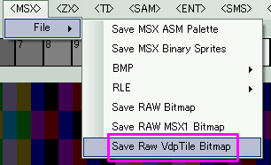
| We can create the bitmap data
using my 'AkuSprite' editor (included in Sources.7z)... For this
example you want to use 'Save
RAW VdpTile Bitmap' This will export the bitmap as a 16 color bitmap, split into simulated 'tiles' |
 |
| Our tiles are held in our program
memory (the normal 64k of the Z80)... but we need to get them to
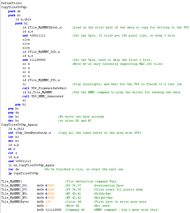
the VDP VRAM to use them later. We do this with the HMMC command.... The VDP has a virtual screen of 256x1024... the area (0,0)-(255,191) is show on screen, if we used a double buffer, it would use the area (0,256)-(256,447) For simplicity, we'll just use the area (0,512)-(256,1023) for out tiles! with 256 pixels on each line, that means we can store 32 tiles per line, so we need to take the first 5 bits of the tile number, and multiply them by 8 to get the X position to store out tile. The Y position will be in the remaining 3 bits, if we multiply them by 8, and add 512, that will be our Y co-ordinate for the tile... Of course each tile is 8x8... and since we're only using a single byte in this calculation, we're only supporting up to 256 tiles. We call HMMC, which will set up the VDP to receive more data ... annoyingly we need to give it the first byte in MyHMMCByte. once we've called call VDP_HMMC_Generated ... we can send the rest of our data, we just do this by OUTing the data to data port (&9B) |
 |
| There is an
alternative version of this in in today code... it's called 'CopyBWTilesToVdp' which uses 2 bit data from our font to define tiles... it's basically the same but has conversions to change the 1bpp data into 4bpp... please see the sources.7z if you want to see it. |
 |
| When we want to get a tile to the
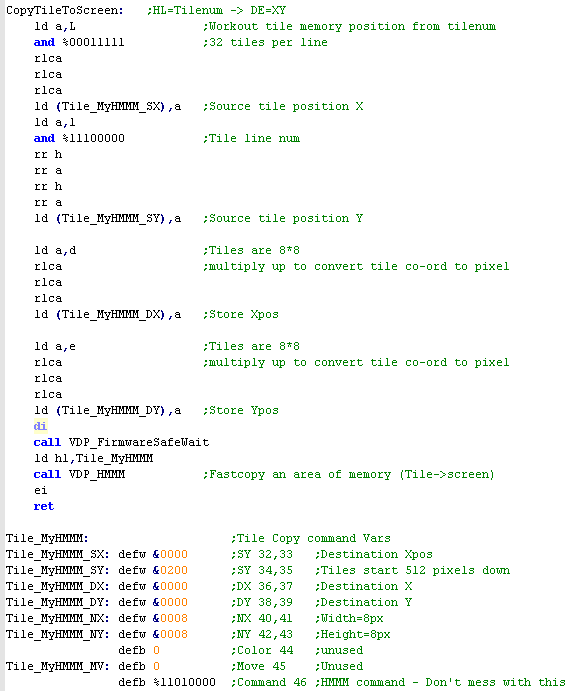
screen, we use 'CopyTileToScreen' This function will set the tile at X,Y position in D,E to tile number HL... This is achieved by copying an 8x8 area from our defined tiles (in the off screen area at Ypos 512+) to the screen. The X,Y position is in 8 pixel units, so the screen is defined as (0,0)-(32,24)... in this way we can use the MSX2 or V9K as a tilemap in the same way as the MSX1 We effectively reverse the calculations we did before, and work out the tile position in the definitions, and copy it to the screen. |
 |
||||||||||||||||||||||||||||||||||||||||||||||||||||||||||||||||||||||||||||||||||||||||||
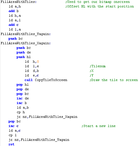
| When we want to draw the Chibiko
bitmap, we will use the 'FillAreaWithTiles function...
this takes an XY position in BC, a Width and Height in HL,
and a start tile number in DE... This function is almost identical to the previous ones, we just use CopyTileToScreen to do our work instead of an OUT command with the MSX1/SMS or a LD (HL) command on the Gameboy... if we call the routine with BC set to &0303 , HL set to &0606 and DE set to 128... the following tiles will be set on screen
|
 |
| We've
covered the tilemap here, want hardware sprites?... Check This
tutorial! |
|
  |
Joypad reading on the Master System and Game Gear |
|
Although
they're usually the same, Joypad reading is one of the times
the SMS and GG are quite different! The SMS has two joypads... and the GG has an extra button (Start!) on a different port! so the commands we run are quite different depending on the machine we're using. |
| The GameGear and Master System
use 3 ports in total, but there are differences! The Gamegear has an extra button! 'Start' accessible from bit 7 of Port &00... The Gamegear does not have any player 2 controls The Mastersystem has no start button, but it does have a second player paddle! note:Button TH has no use on the normal SMS gamepads, so is not used in these examples. |
|
|
|
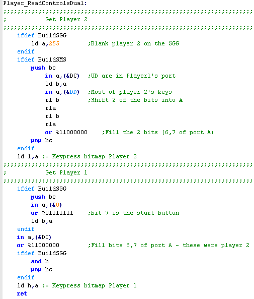
| We'll read Player 2 first, We
need 2 of the bits from &DC, and 4 bits from &DD... we
also need to swap the order of the &DC bits... As we have no Fire 3 or Select, we need to set the top 2 bits to 1 with an OR command Player 2 is saved in L... Next we handle player 1, we read in 6 bits from &DC, and add in the topmost bit of port &00 (Start) on the GameGear ... there is no start button on the Master System Player 1 is saved in H... This returns HL
|
 |
  |
Joypad reading on the Gameboy and Gameboy Color |
| As the
Gameboy does not use OUT commands, the joypad controls are
mapped to memory address &FF00... Strangely it's split into two halves, and we have to write to this address first, to select which half we want to read! |
|
| Joypad reading is all done with
memory address &FF00 Only Bits 0-3 in this address contain the state of the buttons, we first need to select which half of the joystick we want to read. If we write %11101111 to &FF00 (Bit 4 is zero) ... we will select the direction controls... and the next read from &FF00 will get Down, Up, Left, Right in bits 0-3 If we write %11011111 to &FF00 (Bit 5 is zero) ... we will select the button controls... and the next read from &FF00 will get Start, Select, Button B, Button A in bits 0-3 |
|
||||||||||||||||||||||||||||||||||||
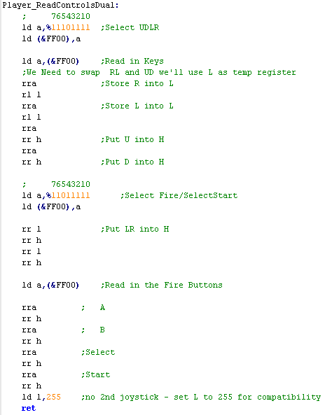
| We start by reading in the
direction controls. So we set bit 4 to 0, and write to
&FF00 You'll notice LR and UD are in the wrong order... we use L as a temporary register to swap these around. We then set bit 5 to 0, and write to &FF00 so we can read in the buttons We then shift in the button bits into H. Finally we write 255 to L, as there is no player 2 controller.
|
 |
||||||||||||||||||||||||||||||||||||
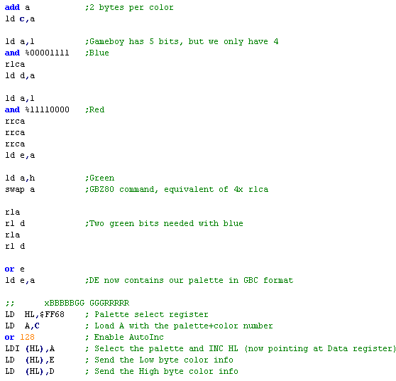
Using our palette definitions
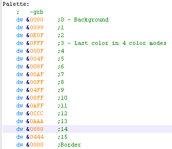
| We're going to use 1 nibble per color channel, in the format
-GRB ... this is the native palette for the CPC+ ... but we're
going to convert it so we can use this one definition on all
our systems... making supporting so many systems much easier. for example &000F is bright blue, and &0800 is 'Middle Green" Some systems have 4 colors (0-3), others 16 (4-15)... and we can also use color 16 to set the border color where appropriate We're going to use the command 'SetPalette' on all systems, for example, to set Color 1 to G=16 R=8 B=4... we can do: LD A,1 LD HL,&0F84 CALL SetPalette |
 |
Using the CPC plus Palette
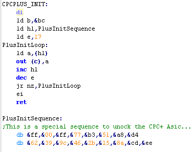
| By default The CPC+ features are disabled, leaving us with
only a regular CPC... to use the PLUS features, we need to
send a series of 17 bytes to the CRTC at port &BCxx once the CPC+ features are on, a special bank of 16k 'ASIC' memory will become available, which we can write to between &4000-&7FFF in the same way as our normal memory. To Turn it on we use: ld bc,&7fb8 out (c),c To turn it off we use: ld bc,&7fa0 out (c),c NOTE: When using the ASIC memory, We should make sure that we're using the 128k banks are disabled, or it can cause problems with some 128k ram upgrades. Mode C1/C3 are OK to use as they page in at &C000 |
 |
|
The bytes
we have to send look strange, but don't think changing them
will have any effect - if you change them they
will not work, and the bytes have no particular meaning... When the Plus Came out, AMS lied and claimed only cartridge games could use the plus features, so they we're intentionally random so no-one could figure out how to use CPC+ features on non-cartridge games! Fortunately we know them now, so we can use PLUS on our tape and disk games! |
| We have to page in the plus
registers so we can write our palette definition into the PLUS
asic... Each color definition is 2 bytes, and there are definitions for the main 16 colors, the border, and CPC+ Hardware Sprites
We send two bytes in the format &-GRB ... where the - nibble is unused, G is Green, R is Red and B is blue |
 |
| We're
using one Nibble per color, so we have a total possible
palette of 4096 colors available to us. We're actually going to use this color definition format for all our systems - some systems support fewer colors, and some support more, but one nibble per color is a good balance and gives us plenty of colors for smooth fading, but doesn't go overboard! |
|
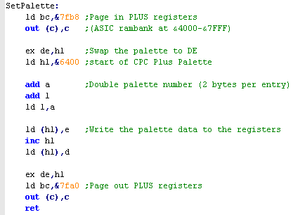
| When we're going to use the
palette definition on the regular CPC, we're only going to use
the top 2 bits of the palette definition, so our RGB
definitions should use F,8,0 .. anything in between will
round DOWN! Setting the color involves two commands ld bc,&7fpp - where pp is the palette number out (c),c out (c),a - where a is the hardware color We keep the hardware colors in a lookup table, which we use to covert the PLUS format colors for the Classic CPC! |
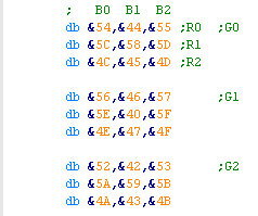 |
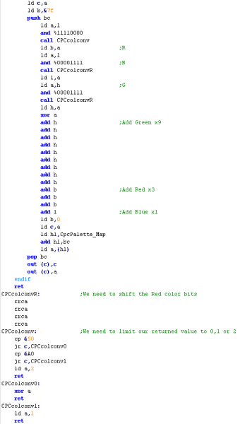
| We need to read in the colors
nibbles, and bit shift them into the appropriate positions, we
then use as an offset for the Lookup table we just saw To get the correct line, we need to multiply the green component by 9, and the Red component by 3, then we just add the blue (times 1!) This gives us the correct position for the closest hardware color the CPC can do... We'll use similar code later again on other 'fixed palette' systems that can't do RGB... and you can easily convert this code to use these palette definitions on systems that aren't even covered by these tutorials. |
 |
 |
We're
setting the colors at the hardware level, so we're using the
firmware color codes, but if you prefer, you could use
the system color numbers (0-26) and use Firmware calls to
set the palette if you prefer... These tutorials tend not to use the firmware, but if it's up to you, so use whatever you prefer... but it's not possible to set PLUS colors via a firmware call! |
  |
Lesson
P14 - Palette definitions on the Enterprise and Sam Coupe Now Lets take a look at the Enterprise, and see how to use our CPC+ style color definitions to define the palette on the Enterprise. |
 |
 |
 |
|
The Enterprise Palette definitions |
| The Enterprise uses 8 bits for each color definition Red and Green have 3 bits defining them, and Blue has only 2... which is quite unbalanced! Also rather oddly the rightmost bits are actually the highest in significance, which is kind of backwards! according to the Enterprise documentation the Calculation for the resulting RGB value is as follows: total RED = ( r2 * 4 + r1 * 2 + r0 ) / 7These definitions are stored in memory in the LPT block, we just need to change that memory to set the new palette values |
Palette Definition as it appears in the LPT:
Effective Palette:
|
||||||||||||||||||||||||||||||||||||||||||||||||||||
| And to make things even stranger,
we can only specify exact colors for the first 8 colors... the
second 8 use a 5 bit 'Bias' ,and pads out the lowest bits with
the "Color Number" (0-7 for colors 8-15) This is controlled by port &80 on the system, so we just OUT our new fixbias byte to that port to change the color This effectively means we are forced to have colors 8-15 as a "rainbow", but we can tint it a bit, or make it brighter or darker. |
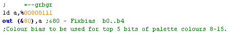
FIXBIAS on port &80:
Effective palette definition of colors 8-15:
Magenta = from palette number bits (values 0-7) Green = from FIXBIAS |
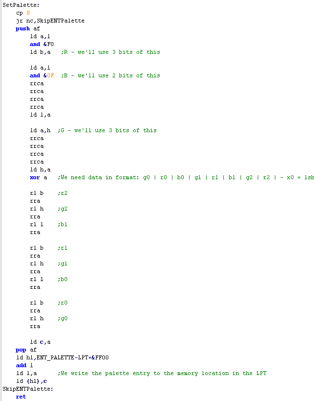
Converting CPC+ color format to the
Enterprise format
| To convert our -GRB format
palette which uses one nibble per color, we just split out the
colors, then shift 3 of the Red and Green bits, and just 2 of
the Blue bits into a new byte, then save that into the LPT
memory for that palette entry Of course, we can only do this for the first 8 colors! |
 |
| When we want to set the top 8
colors in 16 color mode, we can OUT 5 bits to the FIXBIAS
register at port &80 Really, we'll want them to be a brighter, darker or tinted copy of the first colors. |
 |
| The
Enterprise has superior graphics and color to the CPC, so
porting Mode 1 games is really easy! when it comes to Mode 0,
however, the Enterprise is more limited, because we can't set
the 2nd 8 colors as easily on the Enterprise as the CPC, Of course if we're designing a new game then we would plan for this, and design our palette accordingly! |
|
|
The Sam Coupe Palette definitions |
The Sam Coupe uses a 128 color
palette, the RGB part of a color is defined by 2 bits per
channel, and an extra 1 bit is used as a 'Bright' bit, which
increases the brightness by half a bit
The effective color palette is defined as:
Each of the 16 colors is controlled by a different port on the SAM, we OUT our new color byte to that port... If we look at the port numbers in decimal, they don't make much sense, but if we look at them as 16 bit HEX, we'll see that the High byte is the color number, and the low byte is &F8 |
|
|||||||||||||||||||||||||||||||||||||||||||||||||||||||||||||||||||||||||||||||||||||||||||||||||||||||
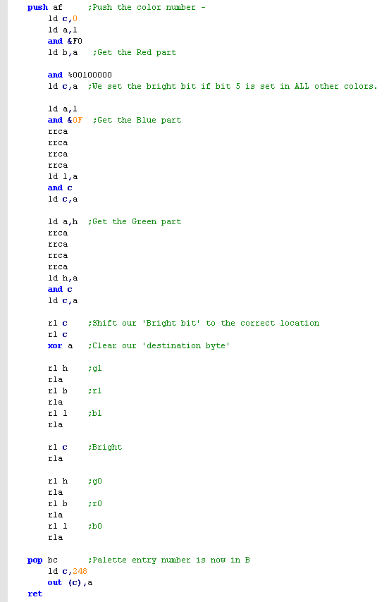
| converting our -RGB one nibble
per channel format to the SAM format is relatively easy,
all we do is pop off 2 bits from each channel into our
destination byte into the correct locations... the only tricky bit is what to do with the 'bright bit'... we could just ignore it, but that would mean bright white would be slightly dark.... In this example, what I've done is set the 'bright bit' when the 2nd bit of each color nibble is set for all three channels... |
 |
 |
Dealing with the
"BRIGHT" bit is tricky because we need to convert our RGB value
some how, Here we've set it when all 3 channels have bit 2 as on This may make the colors seem darker than they should be in some cases but some kind of trade of was needed. Of course you may prefer to set the bit if any of the colors have this bit set, or if 2 of 3 are, but you'll have to change the code! |
The MSX2 V9938
| When we call our routine, we have
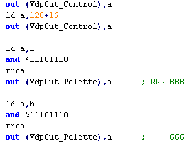
the color number in A, and the -GRB palette definition in HL To set a palette on the MSX2, we need to set register 16 (The indirect palette register) to the number of the palette we want to select. Then we need to send two bytes in the correct format to the palette port on port &9A We need to make some changes to our GRB data... we only need 3 of the 4 bits, and we need to shift the remaining bits one to the right, but apart from that, the data is in the correct format! |
We need to send two consecutive bytes to the Palette port:
 |
The V9K
| We need to use Register 14 to
tell the VDP what color we want to change... we have to shift
this two bits to the left. When we do this, we also tell it what color channel (RGB) we're going to send.. .we're going to leave this as 00 - as it auto increments, and we're going to send all 3 channels. |
Color Selection (Register 14)
C=Channel 0=red 1=Green 2=blue (Auto increments) N=Palette Number 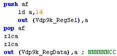 |
||||||||||||||||||||||||||||||||
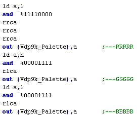
| We need to split out our color
channels and send them one by one, also, although our definition
uses one nibble (4 bits) per channel, the V9K needs 5 bits... so
we need to shift one bit to the left We just send the three bytes to the V9K Palette port (&61) and the color will be set! As we send each byte, the Auto increment means the channel changes, and once we've set a whole 'Color' it automatically moves to the next color, so its easy to set all the colors in one go! |
 |
|
The MSX2
9938 needs 3 bits per channel... the V9K needs 5 per
channel... We're using 4 bits per channel (like the CPC+)... so it's a good middle ground between the other systems... don't you think? |
| During early
development of ChibiAkumas, the MSX2 3 bit color definitions
were used for the V9K,and the CPC+ used separate
definitions... but this meant the V9K fades were noticeably
inferior to the CPC+... The developer switched the code, so the V9K AND MSX2 use the CPC+ palette definitions, and that's why we're using it for ALL the systems in these tutorials! |
|
| The GameGear and Mastersystem use 2x 16 color palettes... Background Tiles can use either of the 2 palettes... sprites always use the second one. The Mastersystem uses just 2 bits per color channel... meaning 1 byte per definition The GameGear uses 1 nibble per channel.. meaning 2 bytes per definition... this means the memory locations are different on the SMS and GG To set one of the bytes that make up the palette definition, we write to an address &C0xx - where xx is the byte of the palette definition we want to change... Note, this isn't literally part of the 16k of VRAM - the &C0 is more like a command to tell the VDP to change a color. |
SMS Palette Definition:
GG Palette Definition:
|
Palettes on the Master System
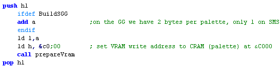
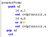
| Our SetPallette command will take
a color number in the Accumulator, and a -GRB color definition
in HL To start, we need to select the memory address - because the Game Gear has 2 bytes per definition, we need to double A on the GG We use the PrepareVram command to send the address to the VDP - which sends the address to vdpControl (&BF) - which tells the VDP what to do with the data it gets next |
  |
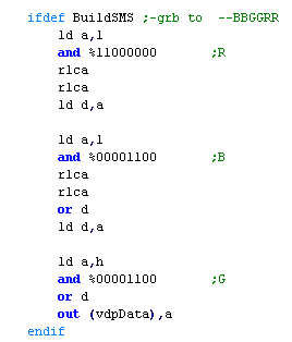
| On the SMS we need the top two
bits of each nibble in our definition... we just merge them all together, and send them to the vdpData port (&BE) to set the color definition! |
 |
Palettes on the Game Gear
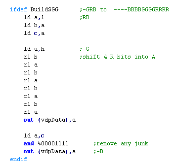
| The GG can take all 4 bits of our
definition! However our definition is in the format -GRB ... and the GG wants it in -BGR format... We need to shift some of the bits of our definition around to get them in the format the GG wants... then we just send the two bytes it needs to the VDP data port! |
 |
| The
superior
palette of the GG is one of the reasons it was possible (via a
converter) to play SMS games on a GameGear, but not the other
way round! even stranger... the 16 bit Sega genesis uses only 3 bits per channel... giving the GG 4096 colors compared to the Genesis' 512 ... so arguably the GG has better color than the Genesis! |
|
| The Classic
Gameboy uses 4 colors for tiles... and there are 4
possible colors that can be used. These colors are defined by 3 memory addresses... &FF47 defines the tilemap colors &FF48 defines sprite colors 0 &FF49 defines sprite colors 1 Just write a byte in the correct format to these addresses to set each color option You can see we have 2 choices for sprite data... also you should note that color 0 (C0) in sprites is transparent. All 3 use the same color definitions, 2 bits in the byte define colors C0-C3... and those bytes can be 0-3 (00,01,10 or 11) |
&FF47,&FF48,&FF49:
Possible Colors
|
||||||||||||||||||||||||||||||||||||||||||||||||||
| The
Gameboy Color has 8 palettes of 4 colors available for
tiles and sprites... each colors is defined by 15 bits... 5 per
channel First we have to select the palette and color we want to change, by writing an appropriate byte to &FF68... Note we also have to set Bit 0 correctly... Our palette definition contains two bytes..a High and Low pair... if we're writing the Low byte bit 7 should be 0... if we're writing the High byte, bit 7 should be 1 Once we've selected the palette destination, we then write the new palette byte to &FF69 We then need to write another byte to &FF68 Rather than doing two writes to &FF68, it's easier to use the Autoinc Bit (bit 7)... this will allow us to write the Low bit, and then the High bit to &FF69... without a second write to &FF68 |
&FF68
- Select Palette
P: Palette (0-7) C: Color (0-3) B: Byte being written to &FF69 (0=L ,1=H) &FF69 - Set Byte of color L / H Byte depending of &FF68
|
||||||||||||||||||||||||||||||||||||||||||||||||||
Colors on the Gameboy Classic
| Because we have such simple color
options we'll just define two palette choices, Dark will set the background to black, the 3rd color to white, and the other two in between... Light will do the opposite! In both cases "Object Palette 1" (the alternate sprite palette) will be the opposite colors of the main palette 0 |
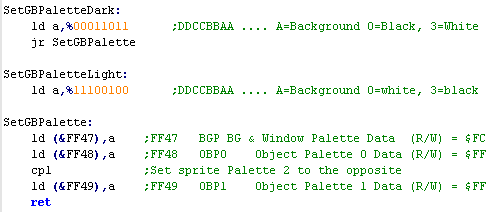 |
| Remember
Color 0 of the sprites will be transparent, so you may want
to customize this depending on your color needs! GrimeZ80 didn't use sprites - it only used tiles, but we'll look at how to use hardware sprites later in the series! |
|
Colors on the Gameboy Color for the Tilemap
| We're providing a color number in
A, and a 1 nibble per channel definition in -GRB format... We need to convert it to 5 bit BGR format - so we need to shift the color bits around We also need to double A because the color number starts in Bit 1 of the data we we write to the palette selector &FF68. We need to write our Palette selector to &FF68., with Bit 0 =0 ... we also set Bit 7 =1 to turn on autoincrement... because we're going to write the low byte first. We've used the special GBZ80 command LDI, so HL will now have changed to &FF69 We've told the graphics hardware we're about to write the LOW byte of the new palette to &FF69... and we'll do that first. Because we've turned on Autoincrement, we can just write the second HIGH byte to &FF69 straight away without changing the selected palette address... we could even set more colors if we wanted. |
 |
|
When we call this function with A=0... HL will be used to define color 0 in palette 0... A=3 will define color 3 in Palette 0... A=4 will define color 0 in Palette 1... this will continue for all 8 (0-7) palettes for a total of 32 colors. |
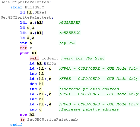
Sprite Colors on the Gameboy Color
| The Sprites use an
alternative 8 palettes... they are set in the same as the
tilemap, however different ports are used... Instead of &FF68, we use &FF6A for the selector, and instead of &FF68 we use &FF6B for the data. |
 |
Introducing ChibiSound!
Terminology!
Music sometimes uses unusual terms for simple things... here's some things you will see in sound chip documentation, and what they actually mean!
AY-3-8910 Registers
| In these tutorials we're going
to create an 'amazing' new sound API to rival
Directsound!!!... well at least the functionality won't break
like Directsound 3D did! Well, no it won't... what it will do is take a byte value from 0-255, and make a sound of selectable pitch, with noise or half volume in a similar way on all our systems! This was created for Grime Z80, and allows common sound code to give similar effects on all the systems! All we do is load the accumulator with a value, and call ChibiSound! Of course, this won't be enough to make music (Hint: try Arkostracker!) but it will give us some simple SFX, and make it easy to compare doing simple tasks on our various systems! |
|
Terminology!
Music sometimes uses unusual terms for simple things... here's some things you will see in sound chip documentation, and what they actually mean!
| Amplitude | Loudness |
| Envelope | How the sound changes over time (on the AY - Volume over time) |
| Mixer | Turn channels on or off |
| Noise | Distorted sounds - used for explosions, drum and symbol sounds |
| Tone | Pitch of the sound |
AY-3-8910 Registers
| The AY Sound chip is controlled
by 14 internal registers that define the sounds it makes...
these are built into the chip itself, and we usually access it
by 2 ports controlled by OUT commands... one selects the
register, the other takes the new value for the register. The procedure is simple, first we send the register number to the register select port Then we send the new value to the data port. before we look at examples of how to make sounds, lets look at the way we access these ports on the systems we'll be looking at, because it's a little differe1nt on each! |
|
 |
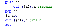
The MSX On the MSX things are easy... the Data port is &A1, and the register select port is &A0 Note: The MSX will have joystick problems if we do not set the top two bits of Reg 7 to %10------ This is because these bits of reg 7 control Port A and B - which are used by the joysticks |
 |
|||||||||||||||||||||||||||||||||||
 |
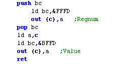
The ZX Spectrum On the Spectrum the procedure is the same, but the ports are different... and of course the Speccy uses 16 bit port numbers... the Data port is &BFFD, and the Register Select is &FFFD |
 |
|||||||||||||||||||||||||||||||||||
 |
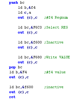
The Amstrad CPC The Amstrad CPC likes to make us suffer!... the AY chip is connected to the "PPI"... so if we want to get to the AY, we need to work for it We need to do a complex sequence of commands to get the PPI to send it's data to the AY, including "Inactive" commands, which are needed to "Reset" the chip between commands... The PPI has 4 ports in total, but we only need two of them to control the AY
&F680 selects to Write to the register &F600 sets the PPI to 'Inactive'... we need to do this at certain times to get it to work &F4xx will send data to the PPI |
 |
|||||||||||||||||||||||||||||||||||
 |
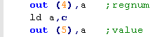
The NeoGeo On the NeoGeo data port is number 5... and the register select port is port 4 The Z80 cpu has its own program code, and data is sent to it using a shared 'Port'... we can only send one byte at a time.... which is good, because Chibisound only uses one byte... Unfortunately commands 0-31 are reserved for system use... so we'll split the Chibisound byte into two nibbles to send it from the 68000 to the Z80 |
 |
|||||||||||||||||||||||||||||||||||
 |
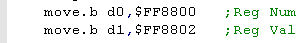
The Atari ST Why's the Atari in here?... well I'm planning a 68000 tutorial series next year, and don't want to make the same video twice! The AY ports are memory mapped on the 68000, so we just write a Byte to $FF8800 to set the register number... and $FF8802 to set the new value for that register! |
 |
| The NeoGeo
sound chip is backwards compatible with the AY... and cannot
be accessed by the 68000, so we have to get the Z80 CPU to
do the sound work... if you want to use the FM side on the
NeoGeo see here The Z80 has its own program code contained in a ROM and separate memory - and we have to pass data between the Z80 and 68000 with a single byte RW port! Writes to Z80 port &0C can be read from 68000 port $320000 , and writes to 68000 port $32000 can be read from port &00 |
|
Getting the AY to work!
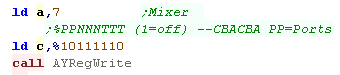
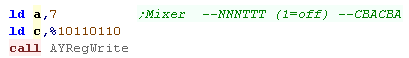
| If we want to do anything, we need to turn
a channel on! The AY has 3 sound channels, A, B and C... rather strangely 0 turns a channel on, and 1 mutes it We turn them on using the Mixer on Reg 7... Bits 0-2 are the normal sounds for channels A-C Bits 3-5 turn noise on for channels A-C in this example, we'll turn on channel A |
 |
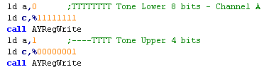
| now we need to select a Pitch... pitches are defined by 12 bits... so each channel has two registers to define a pitch... channel A uses 0 and 1 In this example, we'll set a fairly middle tone for channel A. |
 |
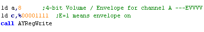
| The last thing we need to do is set a volume for channel
A... this is done with Register 8 A volume can be from 0-16... where 16 is loudest... the sound will now play! We can also turn on an envelope for the channel if we want a more complex sound... |
 |
|
Envelopes
are outside the scope of this tutorial, because the author
is too stupid to understand them properly! please see the AY sound chip PDF if you think you're brainy enough! Essentially an envelope is selected with Register 13... a speed for the envelope with 11 and 12... and it applies for any channel with the envelope bit set in that channel's volume register! |
Making the a noise!
| if we turned on noise for a channel using the Mixer a noise
element will be added to the channel... In this example we've set bit 3 to Zero... turning on noise for channel A |
 |
| All the channels share a common noise setting... to set the noise "Pitch" we use register 6... if takes a 5 bit value, which defines the noise... smaller numbers are higher pitch! | 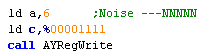 |
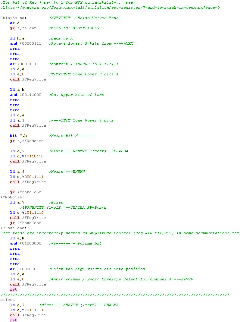
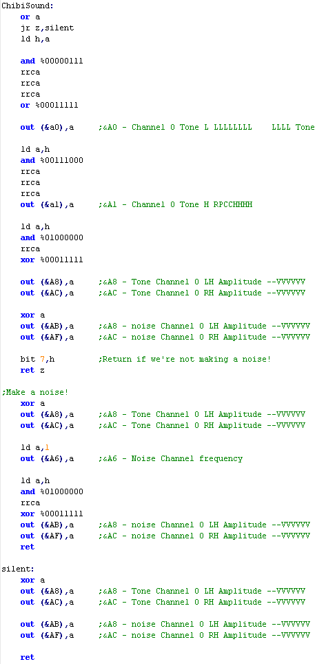
Making Chibisound
| We're now in a position to code
Chibisound! Our Accumulator byte format is NVPPPPP where P= pitch , V = Loud volume, and N is the noise bit We split up PPPPP, and use som,e of the bits to set registers 0 and 1 (Pitch of Channel A) If N is set, we turn the noise channel on using the mixer (0=on) on register 7, then we set a noise frequency using register 6 if N is not set, we only turn on channel A using the mixer on register 7 we also need to set the volume of the channel, otherwise it won't make a sound using register 8 (volume for channel A) %00001111 is the loudest. if A is Zero... we mute all the channels using the mixer - this will stop all sounds |
 |
| The
AY can be 'Tricked' into playing digital sound samples from
WAV files... want to learn how? look here |
|
Enterprise Sound Ports
The Enterprise sound parameters are all controlled by individual ports, so we can simply OUT our values to those ports to select the sound we want to make.
The Enterprise sound parameters are all controlled by individual ports, so we can simply OUT our values to those ports to select the sound we want to make.
| Port | Purpose | Bits | Bit Meaning |
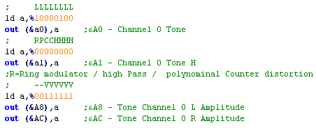
| &A0 | Channel 0 Tone L | LLLLLLLL | L=Tone Low Byte� Lower values=Higher tone |
| &A1 | Channel 0 Tone H | RPCCHHHH | H=Tone High Bits / polynomial Counter / Ring Modulator (CH2) / highPass Filter (CH1) |
| &A2 | Channel 1 Tone L | LLLL | L=Tone Low Byte� Lower values=Higher tone |
| &A3 | Channel 1 Tone H | RPCCHHHH | H=Tone High Bits / polynomial Counter / Ring Modulator (CHN) / highPass Filter (CH2) |
| &A4 | Channel 2 Tone L | LLLL | L=Tone Low Byte� Lower values=Higher tone |
| &A5 | Channel 2 Tone H | RPCCHHHH | H=Tone High Bits / polynomial Counter / Ring Modulator (CH0) / highPass Filter (CHN) |
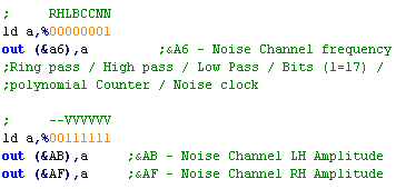
| &A6 | Noise Channel frequency | RHLBCCNN | Noise (0=31khz 1-3=Channel 0-2 link) / polynomial Counter/ swap Bits 7 & 17 of pc / Lowpass /Highpass / Ring modulator |
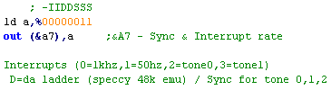
| &A7 | Sync & Interrupt rate | -IIDDSSS | Interrupts (0=1khz,1=50hz,2=tone0,3=tone1) D=da ladder (speccy 48k emu) / Sync for tone 0,1,2 (1=hold 0=run) |
| &A8 | Tone Channel 0 L Amplitude | --VVVVVV | D/A ladder (tape port, Speaker) |
| &A9 | Tone Channel 1 L Amplitude | --VVVVVV | |
| &AA | Tone Channel 2 L Amplitude | --VVVVVV | |
| &AB | Noise Channel L Amplitude | --VVVVVV | |
| &AC | Tone Channel 0 R Amplitude | --VVVVVV | D/A ladder (Speaker R) |
| &AD | Tone Channel 1 RAmplitude | --VVVVVV | |
| &AE | Tone Channel 2 R Amplitude | --VVVVVV | |
| &AF | Noise Channel R Amplitude | --VVVVVV |
Tone Channels
| The Enterprise has 3 tone channels, each one has 12 bits
defining the pitch of the tone (Lower numbers=higher pitch) All the channels are stereo, and the Volume is defined by two 6 bit registers. Despite not having envelopes, we do have some other options... Polynomial Counter Distortion values 0-3 for Off,4bit ,5bit or 7bit... a HighPass filter, and a Ring Modulator The HighPass Filter links to another Channel.... Channel 0 links to Channel 1.... Channel 1 links to Channel 2.... Channel 2 links to the Noise Channel The Ring Modulator also links to another Channel.... Channel 0 links to Channel 2.... Channel 1 links to the Noise Channel .... Channel 2 links to Channel 0
|
 |
|
Try different options for the Polynomial Counter! they'll make the sound different... of course, if you want to use the Ring Modulator or High Pass, you'll have to use an extra channel to link to. |
Noise Channels
| The Noise Channel's frequency is
defined by 2 bits... 0 will give 31khz noise... 1-3 will
link the noise frequency to that of channel 0-2... note Channel
0-2 can be muted, and the noise will work! We also have some extra options! we have the RingPass and HighPass filter, and also a LowPass Filter... Finally we can use the Bit swap option (bit 5) this will swap bit 7 and 17 in the noise generation... the result is the noise sounds more "Synthetic" |
 |
Special Options
| They aren't very useful, but there are some extra options on
the Enterprise for sound... We can change the rate interrupts occur, and even have them linked to the tone channels Also we can make the Enterprise emulate a spectrum Beeper speaker (noooo!) Finally, we can 'Pause' the tone channels, by setting them to 1 in the first 3 bits of this option |
 |
Here comes ChibiSound!
| Our Accumulator byte format is
NVPPPPP where P= pitch , V = Loud volume, and N is the noise bit The Enterprise is pretty easy for us to get ChibiSound Working on! If the sound is off (0) we just mute the Noise and Tone 0 by setting both channels volume bits to 0 For everything else we split up our 6 bit tone definition, and use the bits to define the two tone registers of Channel 0 We use the 1 Volume bit to define a low or high volume... If Noise is not enabled, we're done If noise IS enabled, we mute the Tone channel (though we do need it to some extent!) We then set the Noise volume, and enable Noise linked to channel 0 by writing 1 to port &A6 This will make the noise change pitch as we require! |
 |
| Don't
forget! The Enterprise has a pretty fine AY emulator!
Coded by Geco based on IstvanV's original it's part of
SymAMP, and was used to get ArkosPlayer working on the
Enterprise, for the EP128 port of ChibiAkumas! Of course, ArkosPlayer is 10000x better than ChibiSound, but ChibiSound will be created for every system covered in these tutorials, not just Z80 systems! |
|
|
Beeps not
good enough for you? You can get the AY to play digital wave
files instead... look here! |
| While
the
SAM has 6 tone channels, they can be used as frequency
generators for Envelope an Noise generators, so they may not
all be available for you to make tone sounds with! Still 6 channels is a lot! so it's unlikely to be a problem! |
|
Sam Coupe sound registers
The Sam Coupe has 32 registers - though some have no purpose... write a RegNum to port 511, then a value to port 255 to set one.
| Reg | Purpose | Bits | Bit Meaning |
| 0 | Amplitude generatior 0 | RRRRLLLL | |
| 1 | Amplitude generatior 1 | RRRRLLLL | |
| 2 | Amplitude generatior 2 | RRRRLLLL | |
| 3 | Amplitude generatior 3 | RRRRLLLL | |
| 4 | Amplitude generatior 4 | RRRRLLLL | |
| 5 | Amplitude generatior 5 | RRRRLLLL | |
| 8 | Tone Generator 0 Frequency | FFFFFFFF | Higher num = higher tone |
| 9 | Tone Generator 1 Frequency | FFFFFFFF | |
| 0A | Tone Generator 2 Frequency | FFFFFFFF | |
| 0B | Tone Generator 3 Frequency | FFFFFFFF | |
| 0C | Tone Generator 4 Frequency | FFFFFFFF | |
| 0D | Tone Generator 5 Frequency | FFFFFFFF | |
| 10 | Octive register | -111-000 | Set tone register octives |
| 11 | Octive register | -333-222 | Set tone register octives |
| 12 | Octive register | -555-444 | Set tone register octives |
| 14 | Frequency enable | --543210 | Tone Channel enable 0=off |
| 15 | Noise enable | --543210 | Noise Channel enable 0=off |
| 16 | Noise Generator | --11--00 | 00=31k 01=15k 10=7k 11= freq gen 0 (Chn0) / 1 (Chn3) |
| 18 | Envelope Generator 0 (CH2) | O-GREEEM | envellope controler On / 0= use CH 1 1=timed / Resolution / Envelope shape / Mirror other chanel |
| 19 | Envelope Generator 1 (CH5) | O-GREEEM | envellope controler On / 0= use CH 4 1=timed / Resolution / Envelope shape / Mirror other chanel |
| 1C | Reset and Enable | ------RE | Reset frequency / Enable sound |
Enable Sound
| Before we can use sound we have to turn it on with register &1C | 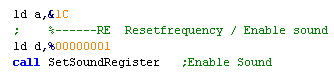 |
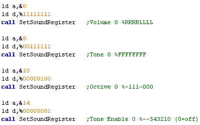
Tone Channels
| There are 4 registers we need to set to make a tone First we need to set the volume, Left and Right channels are defined by a single byte, with one nibble per side... setting Amplitude Generator Reg &0 to 255 will set Tone Channel 0 to max volume Setting the tone is done in two parts, the 'Octive' for Channel 0 is defined by 3 bits in register &10 - each Octive register covers 2 channels.. the top nibble defines Channel 1 The Tone Generator Register (Reg &8 for Channel 0) defines the rest of tone's definition... unlike most systems, Higher numbers are Higher pitch on the SAM... there is one tone generator register per Channel Finally we need to turn on the Channel by setting its bit to 1 ion the Frequency Enable register - Reg &14 |
 |
Noise Channels
| Noise Generation has a wide
variety of options... firstly we have 3 simple frequencies, but
for more power we can link to either Channel 0 for Noise0, or
Channel 3 for Noise1 These are set in register &16 - the Noise Generator register If we want to link to a channel, we have to set that channels frequency... The Noise Generator, links into 3 channels - Noise generatior 1 can output into channels 3,4 and 5, but we need to enable it in the Noise Enable register (reg &5) |
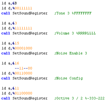 |
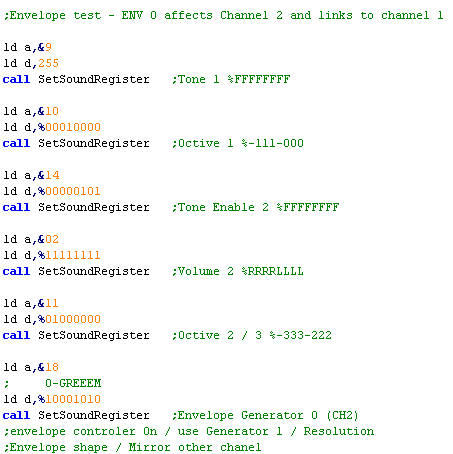
Envelopes
| Envelope Generation can also be
linked to a channel - and it's tone will be used as the speed of
the Envelope... Channel 1 is used for Envelope Controller 0.... which affects Tone Channel 2 Channel 4 is used For Envelope Controller 1.... which affects Tone Channel 5 There are 7 different envelope options available, and you can make the Left and Right channel mirror each other You'll need to check the PDF Datasheet for all the details |
 |
| If you want
to know all the details about the SAM sound chip, download the
PDF
datasheet It's pretty complex, but you'll be able to see how the sound channels relate to each other, and all the Envelope options! |
|
|
If you want more than just the odd beep, take a look here... this tutorial covers playback of wave files for digital sound via WAV files |