

Platform Specific Lessons

Common Data format for Joypad controls used by these tutorials
| On the Z80 We used to read in the buttons and fires into a
single byte... on the 68000 systems we're going to keep the
same format for ULDR Fire1+2 and start... but we'll also
extend into a second byte for any extra fire buttons we
have... for each bit, a 1 means the button is up (unpressed) a 0 means the button is down (pressed) We'll load player 1's joystick data into D0... and player 2's into D1 |
|
||||||||||||||||||||||||||||||||||||
| Our test program is very simple, all it does is read in the two controllers, and show the value of the registers to the screen. | 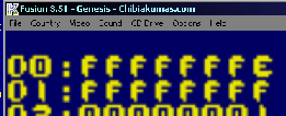 |
Genesis Joystick Ports
Each joystick has two ports - on for Reading or Writing of Data... and one Control port, to set the direction (Read or Write) of each bit of the data port (0=Read, 1=Write)
We will need to set bit 6 to Write to read all the Genesis Buttons
| End address | Description |
| $A10003 | Controller 1 data |
| $A10005 | Controller 2 data |
| $A10009 | Controller 1 control |
| $A1000B | Controller 2 control |
The Genesis Joystick ports are backwards compatible with the Mastersystem, therefore we have to send a sequence of 1's and 0's to the 'TH' bit (Bit 6) to select the different buttons available
Note: Some of the buttons are duplicated in multiple read configurations.
| TH Bit Write | 7 | 6 | 5 | 4 | 3 | 2 | 1 | 0 | Notes |
| 1 | 0 | (TH) | C | B | Right | Left | Down | Up | |
| 0 | 0 | (TH) | Start | A | 0 | 0 | Down | Up | |
| 1,0,1,0,1*,0 | 0 | (TH) | C | B | X | Y | Z | Mode | * should perform a write of 0 to TH afterwards to reset sequence (1,0,1,0,1,0) |
 |
If you
only want to use the basic 3 fires, you can ignore the 3rd
option... also note that not all 6 button joysticks have a
'Mode' button. |
Getting Data from the Joysticks
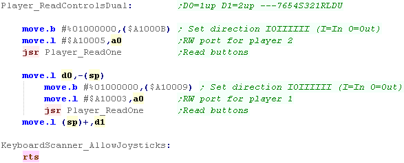
| We're going to process Joystick
2, then Joystick 1, using a common function to do the reading
and bitshifting work (Player_ReadOne) Whichever Joystick we want to read from, we need to first set all the bits to Read EXCEPT bit 6 - which we need to set to Write ,0We then move the data port to use into A0 (as it's different for each joystick) before calling Player_ReadOne |
 |
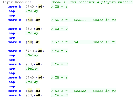
| We need to send commands to the
data port, alternating bit 6 between 1,0,1,0,1,0... we
do to NOP commands to effect a short delay to allow the
joystick hardware to respond to the change. After the 1st,3rd and 5th flip, we need to store a byte, we back these up intoo D1,D2 and D3... we'll use these in a moment. |
 |
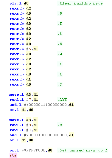
| The bits in D1, D2 and D3 are
in the wrong order, so we're going to do a series of bit
shifts and masks to get the buttons into our 'standard format' We need to get the bit for A and Start into the CBRLDU bits, and M and XYZ are in the wrong order - we want M as the last button |
 |

Mouse Joystick position ports
joysticks on the Amiga connect to the Mouse ports... the data is 'encoded' in the bits of the Horizontal Data
| NAME | ADDR | FUNCTION |
| JOY0DAT | $DFF00A | Joystick-mouse 0 data (vert,horiz) |
| JOY1DAT | $DFF00C | Joystick-mouse 1 data (vert,horiz) |
To covert data from these ports into a traditional digital joystick direction, we need to do some logical operations.
| Direction | Represented
by Bits in $DFF0A/C |
| Right | 1 |
| Left | 9 |
| Down | 1 XOR 0 |
| UP | 9 XOR 8 |
We also need to get the joystick fire buttons from a different port:
| Address | Purpose |
| $BFE001 | FIR1 / FIR0 / RDY / TK0 / WPRO / CHNG / LED / OVL |
| $BFE201 | Direction for bits of port A ($BFE001)... 1=Out / 0=In |
 |
The Amiga
uses the same ports for Mice and Joysticks... we'll assume
Port 0 has a Mouse, and Port 1 has a Joystick... While our code will support 2 joysticks, Port 1's joystick will be Joystick 1, and Port 0's will be Joystick 2. |
Common Data format for Joypad controls used by these tutorials
| On the Z80 We used to read in the buttons and fires into a
single byte... on the 68000 systems we're going to keep the
same format for ULDR Fire1+2 and start... but we'll also
extend into a second byte for any extra fire buttons we
have... for each bit, a 1 means the button is up (unpressed) a 0 means the button is down (pressed) We'll load player 1's joystick data into D0... and player 2's into D1 |
|
||||||||||||||||||||||||||||||||||||
| Our test program is very simple, all it does is read in the two controllers, and show the value of the registers to the screen. | 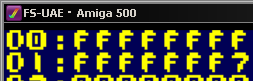 |
Reading the Joysticks
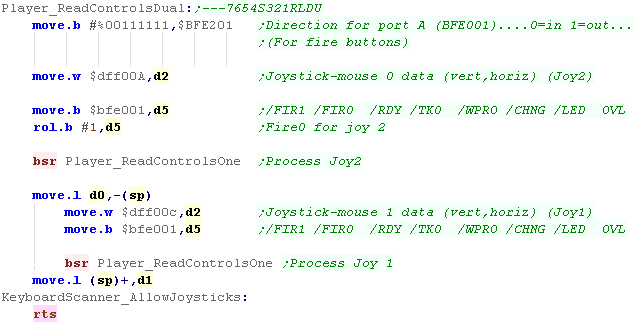
| We're going to need to set the
top two bits of Port A ($BFE001) to READ so we can get the
joystick buttons, Next we'll read joystick 2's XY data from $DFF00A, (we're treating Mouse Port 0 as Joystick 2)... we'll load this into D2. We're also going to load Joystick 2's fire button from $BFE001 into D5... it's in Bit 6, but we need it in bit 7 We're going to call Player_ReadControlsOne to covert the input into the correct format in D0... Once we've done Joystick 2, we push the result onto the stack, and do the same for Joystick 1 |
 |
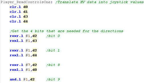
| First we're going to get the 4
bits we need from the Mouse position word into 4 registers
(0,1,8 and 9) We'll need these to calculate the U D L R position of the joystick in a moment. |
 |
| We use the bits we extracted in the last stage to calculate the state of the Up and Down directions, and we shift all the bits into our destination register D0 | 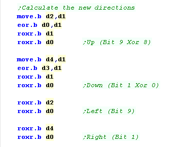 |
| Finally we want to shift in the Fire bit into Bit 4, we then need to flip all the bits of UDLR, and set all the unused bits to 1. | 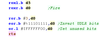 |
| Because there will often be a Mouse plugged into Port 0, Joystick 2 may give unpredictable results, so you should either ignore it, or keep it disabled by default. |  |
Palette Definitions on the x68000
| The Palette on the x68000 use 2
bytes per entry... it uses 5 bits per channel. In our tutorials we use a common palette format, |
|
||||||||||||||||||||||||||||||||||||||||||||||||||||||
| We use Memory addresses
$E82000-$E82220 to define the palettes of the x68000, Each entry uses 2 bytes, and we have different definitions for the Graphics layers, Text layers, and Sprites |
|
Setting the palette
| We define our palette with two
bytes per entry Our code will convert this for every system (Except the QL which has a fixed 8 color palette) |
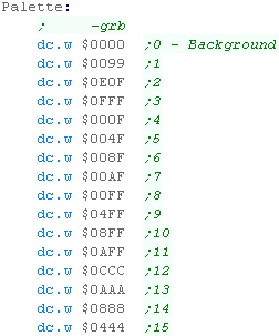 |
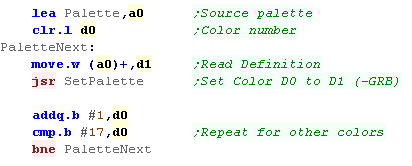
| We're going to use these
definitions with our 'SetPalette' function that will set each
color for us... We just need to loop around all the colors we need. We'll look at SetPalette next... |
 |
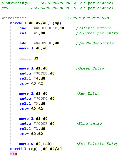
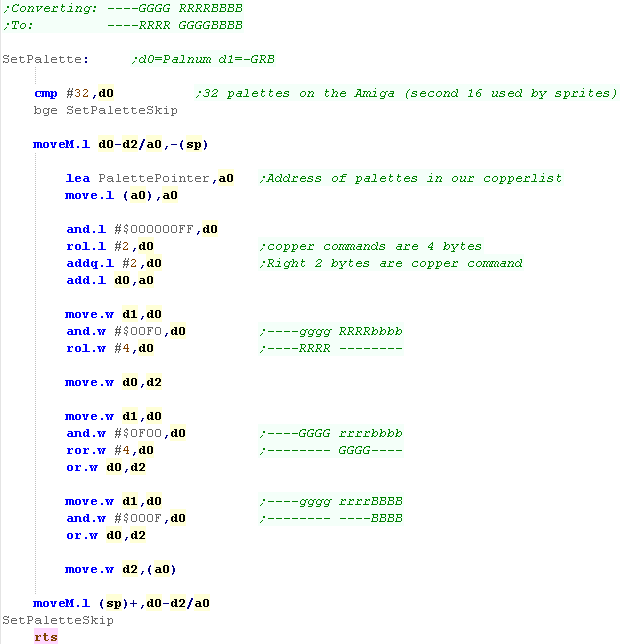
| We need to split up each of our
3 channels, and move them around. Although in the correct GRB order, our definitions are 4 bits per pixel, and the x68000's are 5 bits, we need to shift them around. We also need to calculate the address of the palette we want to change, The palette entries for the background start from $E82000, the sprite palettes start from $E82220 |
 |
| Note that we do not use the 'Text layer' for
our text in these tutorials, we draw directly to the bitmap
layer, so we don't set the text palette here. We WILL be looking at sprites in a later tutorial! |
 |
 |
Lesson
P14 - Palette definitions on
the Atari ST While later versions may have had better color, the basic Atari uses 3 bits per channel, Lets learn how to set the colors with our palette |
 |
 |
|
 |
Palette Definitions on the Atari ST
| The Palette on the Atari ST use
2 bytes per entry... it uses 3 bits per channel. In our tutorials we use a common palette format which uses one nibble per channel We use Memory addresses $FF8240-$FF825F to define the palettes of the Atari ST, Each entry uses 2 bytes |
|
Setting the palette
| We define our palette with two
bytes per entry Our code will convert this for every system (Except the QL which has a fixed 8 color palette) |
|
| We're going to use these
definitions with our 'SetPalette' function that will set each
color for us... We just need to loop around all the colors we need. We'll look at SetPalette next... |
|
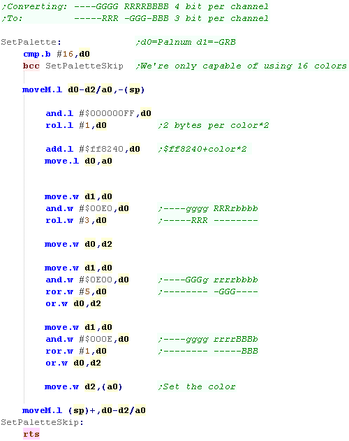
| We need to split up each of our
3 channels, and move them around. Although in the correct GRB order, our definitions are 4 bits per pixel, and the Atari's are 3 bits, we also need to shift them around. We AND with $E (%1110 ) to keep the 3 bits we want and use ROL to shift those bits in the correct position We also need to calculate the address of the palette we want to change, The palette entries start from $ff8240, and each uses 2 bytes, so we do a ROL to double the palette number to get the byte offset |
 |
 |
The
Atari ST has no Hardware sprites or other layers, so these
16 palette entries are all that the basic Atari ST has... The Falcon had more colors, but it's outside of the scope of these tutorials. |
 |
Lesson
P15 - Palette Definitions on
the NeoGeo The NeoGeo uses 5 bits per channel, has 16 colors per palette, and up to 256 palettes! Lets learn how to set the colors on the Neo Geo! |
|
|
|
Palette data is stored between $400000-$401FFF
Each color is 2 bytes in size, there are 16 colors in each palette, and 256 palettes.
The first color in the first palette is special ($400000), it must be $8000... this is called the "Reference color"
The last color in the last palette is special ($401FFE), it is the "Background" color that shows through, when all other layers are transparent
By default, the 'offscreen' border areas of the tilemap are filled with Color $400004
The 16 bits of Color data are in the following format:
| F | E | D | C | B | A | 9 | 8 | 7 | 6 | 5 | 4 | 3 | 2 | 1 | 0 | |
| D | R0 | G0 | B0 | R4 | R3 | R2 | R1 | G4 | G3 | G2 | G1 | B4 | B3 | B2 | B1 |
The Color format is quite odd!
Each color is defined by 5 bits.. .but the lowest bits for each channel is separate from the rest... this means each color can be quickly defined by a single nibble - or all 5 can be used together...
There is also a "Dark" bit... which is effectively the least significant bit for all 3 color channels.
|
The 'Dark
bit' allows an easy way to make all the colors darker, and is
probably most useful to effect a 'pause' option... In these tutorials we use a common format of 4 bits per channel, so we won't use R0,G0 or B0 in these examples. |
| We define our palette with two
bytes per entry Our code will convert this for every system (Except the QL which has a fixed 8 color palette) |
|
| We're going to use these
definitions with our 'SetPalette' function that will set each
color for us... We just need to loop around all the colors we need. We'll look at SetPalette next... |
|
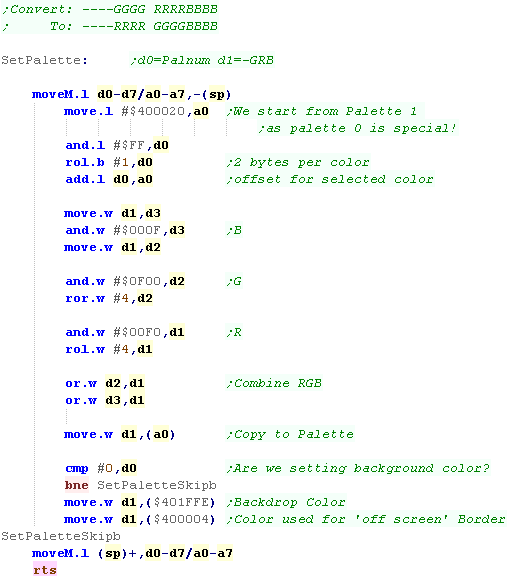
| On the NeoGeo we could use
5 bits per channel, but our definition only has 4. We'll split each of the channels around, and move them using ROR and ROL... When it comes to the palettes, palette ram starts at $400000 with Palette 0... Palette 0 has some special colors, so we'll start using Palette 1 instead - which starts at $400020... Each entry is two bytes, so we double the color number with a ROL Once we've set the main color, we're going to do a check to see if we're setting color 0... If we are, we want to set the common background color at $401FFE.... We're also going to set the 'border color' which uses color 2 of palette 0 at $400004 |
 |
Setting colors on the Genesis is the same as writing to memory... we set the VDP Write address to C0xx0000 - where xx is the byte of the color entry.
| Palette | ColorNum | Address | Palette | ColorNum | Address | Palette | ColorNum | Address | Palette | ColorNum | Address |
| Palette 0 | Color 0 | $C0000000 | Palette 1 | Color 0 | $C0200000 | Palette 2 | Color 0 | $C0400000 | Palette 3 | Color 0 | $C0600000 |
| Color 1 | $C0020000 | Color 1 | $C0220000 | Color 1 | $C0420000 | Color 1 | $C0620000 | ||||
| Color 2 | $C0040000 | Color 2 | $C0240000 | Color 2 | $C0440000 | Color 2 | $C0640000 | ||||
| Color 3 | $C0060000 | Color 3 | $C0260000 | Color 3 | $C0460000 | Color 3 | $C0660000 | ||||
| Color 4 | $C0080000 | Color 4 | $C0280000 | Color 4 | $C0480000 | Color 4 | $C0680000 | ||||
| Color 5 | $C00A0000 | Color 5 | $C02A0000 | Color 5 | $C04A0000 | Color 5 | $C06A0000 | ||||
| Color 6 | $C00C0000 | Color 6 | $C02C0000 | Color 6 | $C04C0000 | Color 6 | $C06C0000 | ||||
| Color 7 | $C00E0000 | Color 7 | $C02E0000 | Color 7 | $C04E0000 | Color 7 | $C06E0000 | ||||
| Color 8 | $C0100000 | Color 8 | $C0300000 | Color 8 | $C0500000 | Color 8 | $C0700000 | ||||
| Color 9 | $C0120000 | Color 9 | $C0320000 | Color 9 | $C0520000 | Color 9 | $C0720000 | ||||
| Color 10 | $C0140000 | Color 10 | $C0340000 | Color 10 | $C0540000 | Color 10 | $C0740000 | ||||
| Color 11 | $C0160000 | Color 11 | $C0360000 | Color 11 | $C0560000 | Color 11 | $C0760000 | ||||
| Color 12 | $C0180000 | Color 12 | $C0380000 | Color 12 | $C0580000 | Color 12 | $C0780000 | ||||
| Color 13 | $C01A0000 | Color 13 | $C03A0000 | Color 13 | $C05A0000 | Color 13 | $C07A0000 | ||||
| Color 14 | $C01C0000 | Color 14 | $C03C0000 | Color 14 | $C05C0000 | Color 14 | $C07C0000 | ||||
| Color 15 | $C01E0000 | Color 15 | $C03E0000 | Color 15 | $C05E0000 | Color 15 | $C07E0000 |
| F | E | D | C | B | A | 9 | 8 | 7 | 6 | 5 | 4 | 3 | 2 | 1 | 0 | |
| - | - | - | - | B2 | B1 | B0 | - | G2 | G1 | G0 | - | R2 | R1 | R0 | - |
| We define our palette with two
bytes per entry Our code will convert this for every system (Except the QL which has a fixed 8 color palette) |
|
| We're going to use these
definitions with our 'SetPalette' function that will set each
color for us... We just need to loop around all the colors we need. We'll look at SetPalette next... |
|
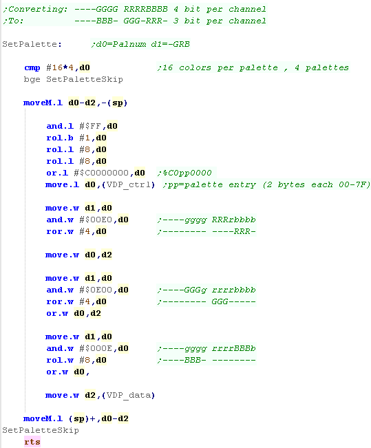
| As each color uses 2 bytes, we're
going to have to double the color number, we're also going to
have to move it from $------XX to $C0XX---- to get the correct
destination memory address We write this to the VDP_CTRL port to select the destination for the new color definition We now need to separate the 3 channels, taking 3 bits of each, We AND with $E (%1110 ) to keep the 3 bits we want and use ROL and ROR to shift those bits in the correct position Now we've built up the new color we write it to VDP_DATA |
 |
|
Remember...
While the MasterSystem had the same palette capabilities, the
Gamegear actually had BETTER 4 bit per channel color! It's got to be a rare case of a 16 bit machine being beaten by it's 8 bit predecessor! |
| Palette definitions on the Amiga are performed by writing to
memory registers between $DFF180 and $DFF1BE Definitions can be performed by writing a word to these registers, with 4 bits per channel in the format shown to the right In these tutorials we use a common format of $_GRB... we will need to convert this to $_RGB for the Amiga |
|
|||||||||||||||||||||||||||||||||||||||||||||||||||||||||||||||||||||||||||||||||||||||||||||||||||
| There are a set of 32 words
between $DFF180 and $DFF1BE, We don't actually set these directly, we want to change them within our copperlist! During our Copperlist definition, we've stored the address of the first palette definition, and we use this to alter the entries in the CopperList. As the copperlist applies to the screen every redraw, changing the copperlist will change the visible colors. |
|
| Although we
'can' write directly to the addresses, it's not practical for
the Amiga. Instead we modify the copperlist in Chip Ram, and that does the job |
|
The Color Changing Code
| It's the Copperlist that actually effectively sets the
colors on the Amiga, so the code that actually sets the colors
is in the v1_BitmapMemory.asm... We store the address of the first palette change code in 'PalettePointer' |
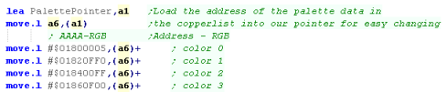 |
| We define our palette with two
bytes per entry Our code will convert this for every system (Except the QL which has a fixed 8 color palette) |
|
| We're going to use these definitions with our 'SetPalette'
function that will set each color for us... We just need to loop around all the colors we need. We'll look at SetPalette next... |
|
| When we want to set the
palette, first we check we're being asked to change a color
less than 31, As our Copperlist entry uses 4 byte entries we rotate our palette number left 2 times to multiply it by 4, We then add 2 - as the left two bytes are the Address (The right 2 are the -RGB palette definition) We now split out each channel from the $-GRB source definition into the $-RGB definition the Amiga needs, Once we've done this we write it to the copperlist address in a0 The color will change during the next screen redraw! |
 |
 |
Lesson
P18 - Sound on
the X68000 The x68000 has a FM sound chip, which we can use to make music, In this tutorial we'll learn how to make simple sounds! |
|
|
|
| For full details of the YM2151 can be found in the YM2151
PDF The FM sound chip has 8 channels.... Each channel's sound can be built up with 4 different 'slots'... meaning there are a total of 32 slots... these slots are turned on or off when the sound is triggered Setting a register is easy, we write the register number to $E90001 , then we write the 8 bit value to $E90003 For registers with 32 slots (eg $60 - volume) we can calculate the address of a channels slot with the formula: Address = RegisterBase + 8*ChannelSlot + Channel So if RegisterBase=$60 , ChannelSlot=3 and Channel=7 then we get $60+24+7 |
Setting
a register on the X68000 move.b #$20,$E90001 ;Reg num move.b #%11000000,$E90003 ;New val |
| Address | 7 | 6 | 5 | 4 | 3 | 2 | 1 | 0 | Summary | Bit Meanings |
| $01 | T | T | T | T | T | T | T | T | Test | T=Test |
| $08 | - | S | S | S | S | C | C | C | Key On (Play Sound) | C=Channel S=Slot (C2 � M2 � C1 � M1) |
| $0F | E | - | - | F | F | F | F | F | Noise | E=noise
enable F=Frequency (Channel 7) |
| $10 | C | C | C | C | C | C | C | C | CLKA1 | |
| $11 | - | - | - | - | - | - | C | C | CLKA2 | |
| $12 | C | C | C | C | C | C | C | C | CLKB | |
| $14 | C | - | F | F | I | I | L | L | C=CSM F=F-Reset I=IRQEN L=LOAD | |
| $18 | L | L | L | L | L | L | L | L | LFREQ | |
| $19 | M | M | M | M | M | M | M | M | PMD/AMD | |
| $1B | D | C | - | - | - | - | W | W | D=fdD force ready C=Clock (4mhz/8mhz) W=Waveform (0=Saw 1=Square,2=Tri, 3=Noise) | |
| $20-$27 | L | R | F | F | F | C | C | C | Chn0-7� | F=Feedback, C=Connection |
| $28-$2F | - | O | O | O | N | N | N | N | Chn0-7� KeyCode | O=Octive, N=Note |
| $30-$37 | F | F | F | F | F | F | - | - | Chn0-7� Key Fraction | F=Fraction |
| $38-$3F | - | P | P | P | - | A | A | A | Chn0-7� PMS / AMS | P=PMS , A=AMS |
| $40-$5F | - | D | D | D | M | M | M | M | Slot0-31. Decay/Mult | D=Decay D1T, M=Mult |
| $60-$7F | - | V | V | V | V | V | V | V | Slot0-31. Volume | V=Volume
(TL) (0=max) |
| $80-$9F | K | K | - | A | A | A | A | A | Slot0-31. Keyscale / Attack | K=Keycale, A=attack |
| $A0-$BF | A | - | - | D | D | D | D | D | Slot0-31. AMS / Decay | A=AMS-EN, D=Decay D1R |
| $C0-$DF | T | T | - | D | D | D | D | D | Slot0-31. DeTune / Decay | T=Detune DT2, D=Decay D2R |
| $E0-$FF | D | D | D | D | R | R | R | R | Slot0-31. Decay / Release | D=Decay D1L, R=Release Rate |
|
The
idea is that we'll use multiple slots on the same channel to make
a complex tone, but that's above what we're going to do in these
tutorials. We're just going to use a single slot to make a simple sound. |
Sfx with Chibisound!
| These tutorials use a sound 'driver' called ChibiSound, Chibisound uses a single byte parameter in D0, and provides 64 different pitches, in low or high volume with either tones or noise. Sending a value of 0 mutes sound, all other values make a tone... Chibisound is intended to make it simple to have SFX in multiplatform games and was used in Grime Z80 and Grime 68000 |
|
Writing Chibisound
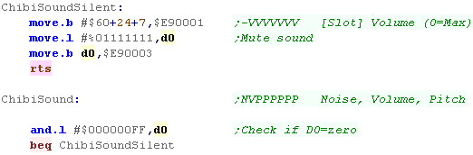
| When Chibisound starts, we need to check if D0 is zero... if it
is, we're going to silence all sound. We use Channel 7, slot 3 for all our sound, so to silence the sound, we just set the volume of the register to 127 (0=loudest 127=silent) |
 |
| First we're going to flip our tone bits, Chibisound needs the
pitch to become higher, as the value of bits 0-6 get lower. Next we're going to set the channel to output to Left and Right channels, we do this by setting the top two bits of $20 Now we're going to set the octive and note we want to play on channel 7, we do this with register $28+7 - we only have 6 bits of pitch, so we shift 1 bit to the left, to get a good range of tones to play |
 |
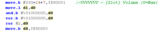
| Now we need to set the volume of the slot we're using (Channel 7
slot 3), we've only got one bit of volume, and in Chibisound 1=loud,
but on the X68000 it's the other way round... We flip the bit, and shift it 2 bits to the right, to get a good balance between the loud and quiet option of Chibisound. |
 |
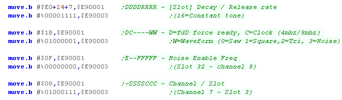
| We need to set the tone length of the slot using using $E0..., we
want the tone to be pretty much constant We need to set a the Clock speed of the sound with bit 6 of $1B - we set it to 1 - which selects 8mhz The top bit actually handles the Floppy disk! - a 1 here forces the drive 'ready' (it doesn't matter to our sound) The bottom two bits select a wave form type - wave 1 is a Square wave. By default we'll turn noise off with $0F We also need to start the tone with reg $08 - we need to play slot 3 of channel 7, as that's what we've been using. |
 |
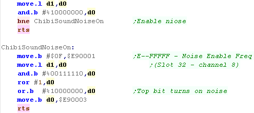
| Ok, the last thing we're going to do is deal with the noise bit...
if the top bit is 1 of the byte passed to chibisound then we want to
turn on noise. The noise register is $0F... this takes 5 frequency bits, so we take 5 of the bits of pitch passed to chibisound... We also need to set the top bit to 1 - this turns on the sound |
 |
|
We've learned
the basics of FM sound on the x68000... but the x68k can also do
digital sound - but that's something we'll have to look at another
day! |
|
Lesson
P19 - Sound on the NeoGeo via
FM with the YM2610 (and Genesis!) We learned how to make sound with the AY backwards compatibility on the NeoGeo in the Z80 Series, but this time we're going to do things properly! Lets learn how to make the NeoGeo make FM sounds! |
|
|
|
|
| We have to
control the sound chip via the Z80 CPU, and it need to be able to
handle sound requests sent by the CPU itself, We're going to use a 'Template' driver from http://www.ajworld.net/neogeodev/beginner/ as a starting point, and build ChibiSound on top |
|
|
Although this is
a NeoGeo lesson, the Genesis can run most of the same Z80 code, as
it's sound chip is compatible... we'll learn how to use this weeks
'ChibiSound' code on the Genesis next time! |
Controling the YM2610
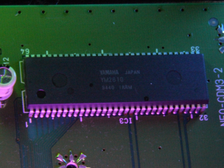
| If you want Get the YM2610
PDF for all the info!
The FM chip uses 2 pairs of ports, $04 and $06 select the address of the register we want to change, $05 and $07 write the new data, but after each write, we need to check if t he FM chip is busy, The YM2610 is very similar to the Genesis sound chip, however on that system there were sound channels 0-5... The NeoGeo has channels 1-4... NOTE: there is no channel 0 ... This is important when we're tuning channels on with $28,Also as there is no Channel 0 - registers &30,&40 etc are all unused |
 The YM2610 in the NeoGeo CD |
| Address | Function | Port $04 / $05 |
Port $06 / $07 |
Bits | Details |
| $21 | LSI Test Data | ALL | TTTTTTTT | T=Test | |
| $22 | LFO Frequency Control | ALL | ----EFFF | E=enable F=Frequency | |
| $24 | Timer A H | ALL | HHHHHHHH | Timer A top 8 bits | |
| $25 | Timer A L | ALL | ------LL | Timer A bottom 2 bits | |
| $26 | Timer B | ALL | TTTTTTTT | T=Timer B | |
| $27 | Timer Control, 2ch mode | ALL | MMRREELL | M=Multi Mode, R=Reset timers, E=enable, L=Load | |
| $28 | Individual Operator Key On/Off | ALL | - | OOOO-GCC | O=operator / G=Channel group / C=Channel (0=chn 1) |
| $31 | Multiplier & Detune | Ch1 Op1 | Ch3 Op1 | -DDDMMMM | D=Detune / M=Multiplier |
| $32 | Multiplier & Detune | Ch2 Op1 | Ch4 Op1 | -DDDMMMM | D=Detune / M=Multiplier |
| $35 | Multiplier & Detune | Ch1 Op2 | Ch3 Op2 | -DDDMMMM | D=Detune / M=Multiplier |
| $36 | Multiplier & Detune | Ch2 Op2 | Ch4 Op2 | -DDDMMMM | D=Detune / M=Multiplier |
| $39 | Multiplier & Detune | Ch1 Op3 | Ch3 Op3 | -DDDMMMM | D=Detune / M=Multiplier |
| $3A | Multiplier & Detune | Ch2 Op3 | Ch4 Op3 | -DDDMMMM | D=Detune / M=Multiplier |
| $3D | Multiplier & Detune | Ch1 Op4 | Ch3 Op4 | -DDDMMMM | D=Detune / M=Multiplier |
| $3E | Multiplier & Detune | Ch2 Op4 | Ch4 Op4 | -DDDMMMM | D=Detune / M=Multiplier |
| $41 | Total Level | Ch1 Op1 | Ch3 Op1 | -TTTTTTT | T=Total Level (0=max) |
| $42 | Total Level | Ch2 Op1 | Ch4 Op1 | -TTTTTTT | T=Total Level (0=max) |
| $45 | Total Level | Ch1 Op2 | Ch3 Op2 | -TTTTTTT | T=Total Level (0=max) |
| $46 | Total Level | Ch2 Op2 | Ch4 Op2 | -TTTTTTT | T=Total Level (0=max) |
| $49 | Total Level | Ch1 Op3 | Ch3 Op3 | -TTTTTTT | T=Total Level (0=max) |
| $4A | Total Level | Ch2 Op3 | Ch4 Op3 | -TTTTTTT | T=Total Level (0=max) |
| $4D | Total Level | Ch1 Op4 | Ch3 Op4 | -TTTTTTT | T=Total Level (0=max) |
| $4E | Total Level | Ch2 Op4 | Ch4 Op4 | -TTTTTTT | T=Total Level (0=max) |
| $51 | Key Scaling & Attack Rate | Ch1 Op1 | Ch3 Op1 | KK-RRRRR | K=Keyscaling / R=attackrate |
| $52 | Key Scaling & Attack Rate | Ch2 Op1 | Ch4 Op1 | KK-RRRRR | K=Keyscaling / R=attackrate |
| $55 | Key Scaling & Attack Rate | Ch1 Op2 | Ch3 Op2 | KK-RRRRR | K=Keyscaling / R=attackrate |
| $56 | Key Scaling & Attack Rate | Ch2 Op2 | Ch4 Op2 | KK-RRRRR | K=Keyscaling / R=attackrate |
| $59 | Key Scaling & Attack Rate | Ch1 Op3 | Ch3 Op3 | KK-RRRRR | K=Keyscaling / R=attackrate |
| $5A | Key Scaling & Attack Rate | Ch2 Op3 | Ch4 Op3 | KK-RRRRR | K=Keyscaling / R=attackrate |
| $5D | Key Scaling & Attack Rate | Ch1 Op4 | Ch3 Op4 | KK-RRRRR | K=Keyscaling / R=attackrate |
| $5E | Key Scaling & Attack Rate | Ch2 Op4 | Ch4 Op4 | KK-RRRRR | K=Keyscaling / R=attackrate |
| $61 | Decay Rate & AM Enable | Ch1 Op1 | Ch3 Op1 | A--DDDDD | A=Amplitude Mod Enable / D= Decay rate |
| $62 | Decay Rate & AM Enable | Ch2 Op1 | Ch4 Op1 | A--DDDDD | A=Amplitude Mod Enable / D= Decay rate |
| $65 | Decay Rate & AM Enable | Ch1 Op2 | Ch3 Op2 | A--DDDDD | A=Amplitude Mod Enable / D= Decay rate |
| $66 | Decay Rate & AM Enable | Ch2 Op2 | Ch4 Op2 | A--DDDDD | A=Amplitude Mod Enable / D= Decay rate |
| $69 | Decay Rate & AM Enable | Ch1 Op3 | Ch3 Op3 | A--DDDDD | A=Amplitude Mod Enable / D= Decay rate |
| $6A | Decay Rate & AM Enable | Ch2 Op3 | Ch4 Op3 | A--DDDDD | A=Amplitude Mod Enable / D= Decay rate |
| $6D | Decay Rate & AM Enable | Ch1 Op4 | Ch3 Op4 | A--DDDDD | A=Amplitude Mod Enable / D= Decay rate |
| $6E | Decay Rate & AM Enable | Ch2 Op4 | Ch4 Op4 | A--DDDDD | A=Amplitude Mod Enable / D= Decay rate |
| $71 | Sustain Rate | Ch1 Op1 | Ch3 Op1 | ---SSSSS | S=Sustain Rate |
| $72 | Sustain Rate | Ch2 Op1 | Ch4 Op1 | ---SSSSS | S=Sustain Rate |
| $75 | Sustain Rate | Ch1 Op2 | Ch3 Op2 | ---SSSSS | S=Sustain Rate |
| $76 | Sustain Rate | Ch2 Op2 | Ch4 Op2 | ---SSSSS | S=Sustain Rate |
| $79 | Sustain Rate | Ch1 Op3 | Ch3 Op3 | ---SSSSS | S=Sustain Rate |
| $7A | Sustain Rate | Ch2 Op3 | Ch4 Op3 | ---SSSSS | S=Sustain Rate |
| $7D | Sustain Rate | Ch1 Op4 | Ch3 Op4 | ---SSSSS | S=Sustain Rate |
| $7E | Sustain Rate | Ch2 Op4 | Ch4 Op4 | ---SSSSS | S=Sustain Rate |
| $81 | Release Rate & Sustain Level | Ch1 Op1 | Ch3 Op1 | SSSSRRRR | S=Sustain Level / Release Rate |
| $82 | Release Rate & Sustain Level | Ch2 Op1 | Ch4 Op1 | SSSSRRRR | S=Sustain Level / Release Rate |
| $85 | Release Rate & Sustain Level | Ch1 Op2 | Ch3 Op2 | SSSSRRRR | S=Sustain Level / Release Rate |
| $86 | Release Rate & Sustain Level | Ch2 Op2 | Ch4 Op2 | SSSSRRRR | S=Sustain Level / Release Rate |
| $89 | Release Rate & Sustain Level | Ch1 Op3 | Ch3 Op3 | SSSSRRRR | S=Sustain Level / Release Rate |
| $8A | Release Rate & Sustain Level | Ch2 Op3 | Ch4 Op3 | SSSSRRRR | S=Sustain Level / Release Rate |
| $8D | Release Rate & Sustain Level | Ch1 Op4 | Ch3 Op4 | SSSSRRRR | S=Sustain Level / Release Rate |
| $8E | Release Rate & Sustain Level | Ch2 Op4 | Ch4 Op4 | SSSSRRRR | S=Sustain Level / Release Rate |
| $91 | SSG-Envelope Generator | Ch1 Op1 | Ch3 Op1 | ----EEEE | E=Envelope Gen |
| $92 | SSG-Envelope Generator | Ch2 Op1 | Ch4 Op1 | ----EEEE | E=Envelope Gen |
| $95 | SSG-Envelope Generator | Ch1 Op2 | Ch3 Op2 | ----EEEE | E=Envelope Gen |
| $96 | SSG-Envelope Generator | Ch2 Op2 | Ch4 Op2 | ----EEEE | E=Envelope Gen |
| $99 | SSG-Envelope Generator | Ch1 Op3 | Ch3 Op3 | ----EEEE | E=Envelope Gen |
| $9A | SSG-Envelope Generator | Ch2 Op3 | Ch4 Op3 | ----EEEE | E=Envelope Gen |
| $9D | SSG-Envelope Generator | Ch1 Op4 | Ch3 Op4 | ----EEEE | E=Envelope Gen |
| $9E | SSG-Envelope Generator | Ch2 Op4 | Ch4 Op4 | ----EEEE | E=Envelope Gen |
| $A1 | Frequency low (Write Second) | Ch1 | Ch3 | PPPPPPPP | P=Frequency Position L |
| $A2 | Frequency low (Write Second) | Ch2 | Ch4 | PPPPPPPP | P=Frequency Position L |
| $A5 | Frequency high & Octave (Write first) | Ch1 | Ch3 | --OOOPPP | O=Octive / P=Position H |
| $A6 | Frequency high & Octave (Write first) | Ch2 | Ch4 | --OOOPPP | O=Octive / P=Position H |
| $A9 | Frequency low during Multi-Mode | Ch1 | Ch3 | PPPPPPPP | P=Frequency Position L |
| $AA | Frequency low during Multi-Mode | Ch2 | Ch4 | PPPPPPPP | P=Frequency Position L |
| $AD | Frequency high & Octave during Multi-Mode | Ch1 | Ch3 | --OOOPPP | O=Octive / P=Position H |
| $AE | Frequency high & Octave during Multi-Mode | Ch2 | Ch4 | --OOOPPP | O=Octive / P=Position H |
| $B1 | Algorithm & Feedback | Ch1 | Ch3 | --FFFAAA | F=Feedback / A=Algorithm |
| $B2 | Algorithm & Feedback | Ch2 | Ch4 | --FFFAAA | F=Feedback / A=Algorithm |
| $B5 | FMS & AMS & Stereo | Ch1 | Ch3 | LRAA-FFF | Left / Right (1=on) / A=Amplitude Mod Sensitivity / F=Frequency Mod Sensitivity |
| $B6 | FMS & AMS & Stereo | Ch2 | Ch4 | LRAA-FFF | Left / Right (1=on) / A=Amplitude Mod Sensitivity / F=Frequency Mod Sensitivity |
|
The NeoGeo FM
Sound chip is compatible with the Genesis - the Genesis has 2
extra sound channels, but code written for the NeoGeo will work
fine on the Genesis, as the port numbers are the same... Genesis code would need rewriting for the NeoGeo, as the 2 channels are missing on the NeoGeo (which is why there is no $60, $70 etc) |
| The NeoGeo sound
chip is backwards compatible with the AY... and cannot be accessed
by the 68000, so we have to get the Z80 CPU to do the sound
work... The Z80 has its own program code contained in a ROM and separate memory - and we have to pass data betrween the Z80 and 68000 with a single byte RW port! Writes to Z80 port &0C can be read from 68000 port $320000 , and writes to 68000 port $320000 can be read from port &00 |
 |
Sound Ports
Communication between the Z80 and 68000 work with the following ports
| Z80 |
68000 |
|
| Read |
Port &00 | Address $320000 |
| Write |
Port &0C | Address $320000 |
Sfx with Chibisound!
| These tutorials use a sound 'driver' called ChibiSound, Chibisound uses a single byte parameter in D0, and provides 64 different pitches, in low or high volume with either tones or noise. Sending a value of 0 mutes sound, all other values make a tone... Chibisound is intended to make it simple to have SFX in multiplatform games and was used in Grime Z80 and Grime 68000 |
|
Writing Chibisound
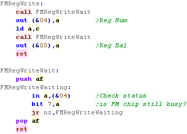
| We have to write Z80 code to use the FM sound
chip on the NeoGeo We're going to write a function called 'FMRegWrite'.... this will set Reg A to value C... We do this by writing the register number to port &04... and we're going to write the new value to port &05 before each write, we need to check if the sound chip is still busy... to do this we read in from &04, if the top bit is 1, then it's still busy, so we wait until it's not. |
 |
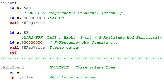
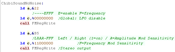
| First we're going to check if A is zero - if it is we want to turn
off all sound... we do this by clearing 'Key on' in Reg &28 (Key On starts a sound)... we then set the LR channel mapping with &B5 - setting the top two bits to zero means the channel plays on Neither Left or Right channel - so the sound does not play. |
 |
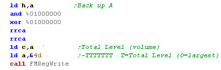
| We back up the accumulator into H for while we're working First we'll set the volume, bit 6 in our byte is our volume (1=high) We're going to use Channel 1 Op4 for all our sound... on the YM2610 0 is loudest, so we need to flip the bit, and rotate it right 2 bits to make the sound a good volume level |
 |
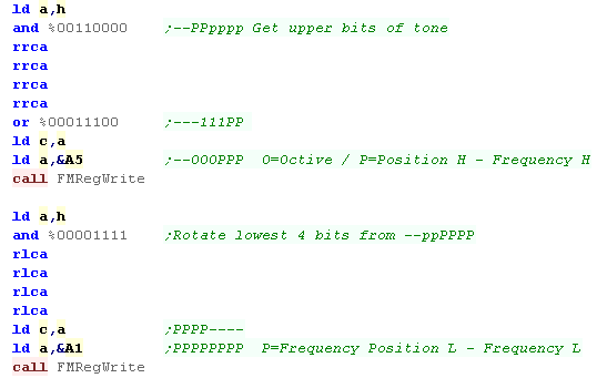
| Next we're going to set the pitch... Chibisound has 6 pitch bits. On the FM soundchip there are 2 registers controlling the pitch of Channel 1 - &A5 is the high byte, and &A1 is the low byte... We split the 6 bits up in two, and distribute them across both registers. |
 |
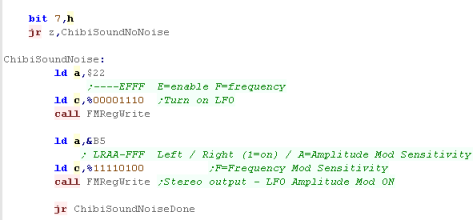
| Next we're going to check our noise bit - the top bit passed to
chibisound. If the top bit is 1 we want to turn on noise - we do
this with the LFO We set the frequency of the LFO with bits 0-2 of reg &22, we also enable LFO with bit 3 We also need to set how the LFO will affect the sound - we do ths with reg &B5... Bits 0-2 set how the LFO alters the frequency, bit 4,5 set how the LFO affect the amplitude... We also need to set bits 6,7 - these set how the channel maps to the speakers, we want to enable both Left and Right - effectively making a mono channel We also need to set the top bit of &6D to enable the LFO Amplitude mod, but we'll do that later |
 |
| If we're not using Noise we want to turn off the LFO, we set all
the bits of &22 to zero We still need to set the top two bits (6,7) of &B5 - if we don't there won't be any sound! |
 |
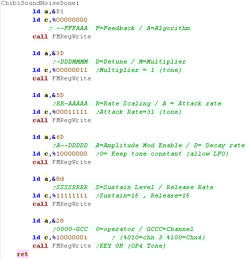
| We're going to use algorithm 0 - this is the simplest, where each
op links in a line to the next (we're only using Op4 in our code
here)... you can see all the different algorithms
here ... We set this with &B1 Next we need to set the 'Multiplier' - changing the multiplier will alter the pitch - we'll set it to 1 We need to define the way our tone sounds over time next (details here) We're going to set the minumum Attarck rate ($5D) - this makes our tone reach maximum as fast as possible We'll also set the maximum sustain and release rate ($8D) we want our note to be basically constant We need to set the top bit of $6D to ensure the LFO will work (when it's on - it has no effect if off), we also set the Decay rate Finally we want to turn on our sound... we've programmed Op4 of Channel 1 - so we need to set bits 0 and 7 to 1 in reg &28 to make the tone play. |
 |
|
The NeoGeo sound
chip doesn't just do FM sound - it can also do ADPCM sound, but
that's beyond what we can look at here. |
Sending data from the 68000 to the z80 and Chibisound
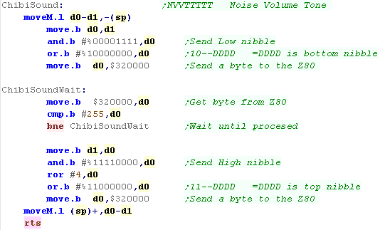
| We have to talk to the z80 in single bytes.. If the 68000 writes a byte to $320000, the z80 can read it from port &00 If the z80 writes a byte to port &0C, the 68000 can read it from $320000, Unfortunately, because the NeoGeo bios reserves values 0-31, we're going to have to be tricky when we send the ChibiSound byte... We'll split it into 2 nibbles, and send them in two halves, we wait until a signal byte of &255 to tell us that the first half has been recieved |
 |
| When the Z80 receives a byte an NMI call will occur to address
&0066... when this happens we read in from port &00 We need to process system commands 0/1/2... Any command with the top bit (bit7) is set is a Chibisound command. If bit 6 is zero then we're receiving the low nibble... we store the nibble in address 'ChibiSoundTemp', and send a 255 back to the 68000 by writing to port &0C if bit 6 is one then we're receiving the high nibble, we merge it with the previous low nibble, and send the result to the ChibiSound driver. |
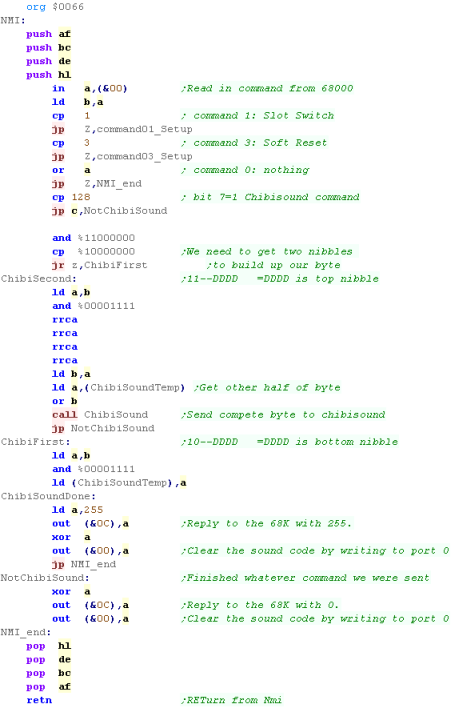 |
| We're only handling commands 0-3 of the NeoGeo bios
here, but really we should support more... that's why we're not
hearing the NeoGeo sound when the system starts. The full list is shown here |
|
The Genesis and the Z80
| The Z80 and 68000 share 8K of RAM, on the Z80 side this is at area
$0000-$1FFF, on the 68000 this area is $A00000-$A01FFF We have to 'Lock' the ram (stopping the Z80) to write to the ram from the 68000 side, We do this by writing $100 to $A11100, we need to read back a word from $A11100 and wait until bit 8 is zero... this tells us the Z80 is paused We unlock the z80 by writing $000 to $A11100 We reset the Z80 by writing $100 to $A11200 |
Z80:
|
68000:
|
|
The
Z80 on the Genesis is used for backwards compatibility with the
Master System, and it can also access the legacy sound of the
76489 that was used by the master system, But the Z80 gives us great potential for playing music - after all it's MUCH easier to code a Z80 music player than the SNES SPC700 one - and we can use the same FM music player on the Z80 NeoGeo or PSG player on the SMS |
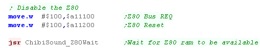
| We've covered the theory of the Z80, lets make it work! First we need to stop the Z80, and wait for the 68000 to be able to write Z80 ram |
 |
| Next we need to copy our program into the Z80 address space ($A00xxxx on the 68000 = &xxxx on the z80) | 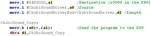 |
| Once our program has been copied we want to restart the Z80, the Z80 will start executing memory address &0000 in its ram | 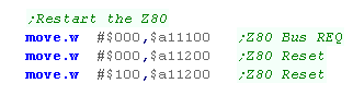 |
| We will need to pause before writing data until the Z80 has stopped, we can test this by checking bit 8 of the word at $A11100 | 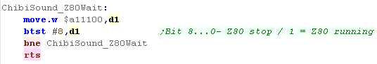 |
| We will need to compile our program as Z80 bytecode and include it in the program. | 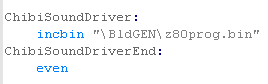 |
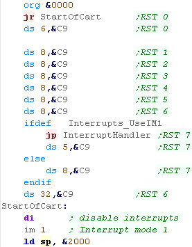
A valid header for a Z80 sound program
| We need some kind of Z80 program for the sound chip to run, When the Z80 starts, it executes memory address &0000... we're going to define some RST's, and set them all to return commands (&C9)... the Z80 can receive Vblank interrupts, but we won't use them in this example When our actual program starts, we need to set up a valid stack pointer, we'll set Interrupt Mode 1 and we'll disable interrupts. We can now put our actual sound handling code! |
 |
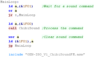
Chibisound for the Genesis Z80
| Chbisound uses a single command byte, When we want to pass a command to Chibisound, we're going to write it to &1F00 ... but we're going to use a second byte at &1F01 as a 'execute' command... When &1F01 becomes nonzero, we'll send the byte at &1F00 to chibisound, then we'll reset &1F01 the code of "GEN-Z80_V1_ChibiSoundFM.asm" is IDENTICAL to the NeoGeo version - so please see Lesson P19 above. |
 |
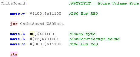
| When the 68000 wants to send the bytes to the Z80, first it needs
to request the bus using $A011100, and wait for the bus to be
available, Then we can write our bytes, finally we release the bus so the Z80 can continue processing. |
 |
|
It's pretty
dumb to use the Z80 for such a simple task, but if we were playing
music we could use the Vsync timing to run interrupts and get the
Z80 to play the music, without using any of the 68000 cpu power,
that way we don't need to worry about timing from the 68000 side,
and our music won't slow down if the 68000 is really busy! |
| View Options |
| Default Dark |
| Simple (Hide this menu) |
| Print Mode (white background) |
| Top Menu |
| ***Main Menu*** |
| Youtube channel |
| Patreon |
| Introduction to Assembly (Basics for absolute beginners) |
| Amazon Affiliate Link |
| AkuSprite Editor |
| ChibiTracker |
| Dec/Bin/Hex/Oct/Ascii Table |
| Alt Tech |
| Archive.org |
| Bitchute |
| Odysee |
| Rumble |
| DailyMotion |
| Please note: I wlll upload more content to these alt platforms based on the views they bring in |
| 68000 Content |
| ***68000 Tutorial List*** |
Learn 68000 Assembly  |
| Hello World Series |
| Platform Specific Series |
| Simple Samples |
| Grime 68000 |
| 68000 Downloads |
| 68000 Cheatsheet |
| Sources.7z |
| DevTools kit |
| 68000 Platforms |
| Amiga 500 |
| Atari ST |
| Neo Geo |
| Sega Genesis / Mega Drive |
| Sinclair QL |
| X68000 (Sharp x68k) |
| 8086 Content |
| Learn 8086 Assembly |
| Platform Specific Series |
| Hello World Series |
| Simple Samples |
| 8086 Downloads |
| 8086 Cheatsheet |
| Sources.7z |
| DevTools kit |
| 8086 Platforms |
| Wonderswan |
| MsDos |
| ARM Content |
| Learn ARM Assembly |
| Learn ARM Thumb Assembly |
| Platform Specific Series |
| Hello World |
| Simple Samples |
| ARM Downloads |
| ARM Cheatsheet |
| Sources.7z |
| DevTools kit |
| ARM Platforms |
| Gameboy Advance |
| Nintendo DS |
| Risc Os |
| Risc-V Content |
| Learn Risc-V Assembly |
| Risc-V Downloads |
| Risc-V Cheatsheet |
| Sources.7z |
| DevTools kit |
| MIPS Content |
| Learn Risc-V Assembly |
| Platform Specific Series |
| Hello World |
| Simple Samples |
| MIPS Downloads |
| MIPS Cheatsheet |
| Sources.7z |
| DevTools kit |
| MIPS Platforms |
| Playstation |
| N64 |
| PDP-11 Content |
| Learn PDP-11 Assembly |
| Platform Specific Series |
| Simple Samples |
| PDP-11 Downloads |
| PDP-11 Cheatsheet |
| Sources.7z |
| DevTools kit |
| PDP-11 Platforms |
| PDP-11 |
| UKNC |
| TMS9900 Content |
| Learn TMS9900 Assembly |
| Platform Specific Series |
| Hello World |
| TMS9900 Downloads |
| TMS9900 Cheatsheet |
| Sources.7z |
| DevTools kit |
| TMS9900 Platforms |
| Ti 99 |
| 6809 Content |
| Learn 6809 Assembly |
| Learn 6309 Assembly |
| Platform Specific Series |
| Hello World Series |
| Simple Samples |
| 6809 Downloads |
| 6809/6309 Cheatsheet |
| Sources.7z |
| DevTools kit |
| 6809 Platforms |
| Dragon 32/Tandy Coco |
| Fujitsu FM7 |
| TRS-80 Coco 3 |
| Vectrex |
| 65816 Content |
| Learn 65816 Assembly |
| Hello World |
| Simple Samples |
| 65816 Downloads |
| 65816 Cheatsheet |
| Sources.7z |
| DevTools kit |
| 65816 Platforms |
| SNES |
| eZ80 Content |
| Learn eZ80 Assembly |
| Platform Specific Series |
| eZ80 Downloads |
| eZ80 Cheatsheet |
| Sources.7z |
| DevTools kit |
| eZ80 Platforms |
| Ti84 PCE |
| IBM370 Content |
| Learn IBM370 Assembly |
| Simple Samples |
| IBM370 Downloads |
| IBM370 Cheatsheet |
| Sources.7z |
| DevTools kit |
| Super-H Content |
| Learn SH2 Assembly |
| Hello World Series |
| Simple Samples |
| SH2 Downloads |
| SH2 Cheatsheet |
| Sources.7z |
| DevTools kit |
| SH2 Platforms |
| 32x |
| Saturn |
| PowerPC Content |
| Learn PowerPC Assembly |
| Hello World Series |
| Simple Samples |
| PowerPC Downloads |
| PowerPC Cheatsheet |
| Sources.7z |
| DevTools kit |
| PowerPC Platforms |
| Gamecube |
| Work in Progress |
| ChibiAndroids |
| Misc bits |
| Ruby programming |
Buy my Assembly programming book
on Amazon in Print or Kindle!


Available worldwide!
Search 'ChibiAkumas' on
your local Amazon website!
Click here for more info!


Buy my Assembly programming book
on Amazon in Print or Kindle!
Available worldwide!
Search 'ChibiAkumas' on
your local Amazon website!
Click here for more info!
Buy my Assembly programming book
on Amazon in Print or Kindle!
Available worldwide!
Search 'ChibiAkumas' on
your local Amazon website!
Click here for more info!