

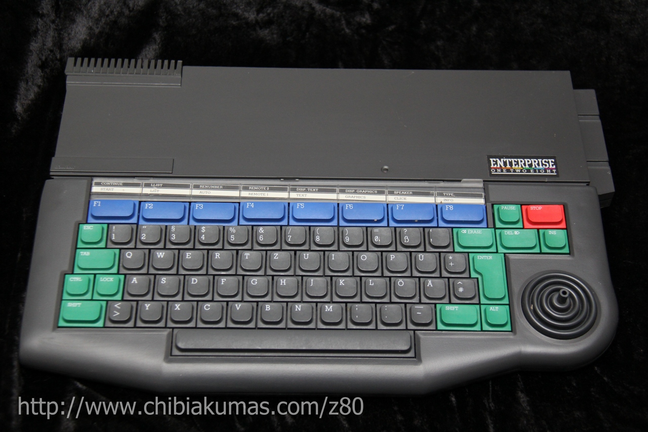
Z80 Assembly programming for the Elan Enterprise 128
What is the Enterprise 128?
The Enterprise doesn't just have more colors though! compared to the CPC, a screen that can be split into sections, and each section can be a different screen mode and color palette - this can be done with clever interrupts on the CPC, but the Enterprise does this in hardware, without interrupts or cpu power used - allowing for far more colorsplits, The color palette is also better - the regular CPC has 27 possible colors, but the Enterprise has 256
The Basic Enterprise has 64k, but
we'll be focusing on the 256k version
|
 |
Useful Documents
EXOS20_technical_information.pdf
ChibiAkumas Tutorials
Memory Banks
| The Enterprise and it's OS supports up to 256x 16k banks for an
insane 4MB of memory (though some may be rom!) The most basic system supports 64k, but there is also a 128k version (the EP128)... There are two special segments... the Zero Segment containing the RST's, and our program, (loaded at &0000) and the system segment (loaded at &8000 by default)... around 2/3rds of the system bank will be used by the OS... the rest will be free. it's important to notice, ONLY memory banks in the base 64k (&FC FD FE FF) can be used for video memory. We can use the Zero page bank if we want... but we must 'request' ALL other banks from the OS before using them... it will find one, and tell us what it's allocated - if all the banks are used, it will give us the spare memory of the system page, The diagram to the right, shows how the OS allocates memory on these two systems. Essentially the internal memory has bank numbers 255-252 (FF-FC)... as we add more memory, we will get lower and lower numbered banks... for example a 256k system will have banks down to 240 (F0) The top bank (255) is used as the system segment... the bottom bank (number will depend on upgrades) will be the Zero page... The system will allocate banks in consecutive order... so we won't use the internal 64k until we have no choice... this means we can be sure to have it available for Vram! Low numbers (for example banks 0-4) will be rom. Bank switching is performed by simply writing the bank number (Eg &FC) to the ports &BO &B1 &B2 and &B3 with an OUT command |
64k
Bank
(Can be Vram)
Extended bank (Cannot be vram) Banks witching Ports:
|
| We can ask the OS for memory, and then use it for whatever we
want... if we don't need it any more, we can tell the OS to take it
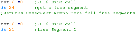
back! This is how we get a free VRAM bank... we ask for memory banks, until we get one >=FC (a 64k internal bank)... This may take a while, as the OS gives us the low numbered banks first... but once we get one, we can just free up all the ones we didn't really want! We use RST 6 to do an EXOS call... and command 24 to request a segment, and 25 to give it back! |
 |
Lets look at the details of these two commands:
EXOS Function 24 - Allocate Segment
This command will request another 16k segment... status reg will be Zero if succeeded, NZ if another full 16k is not available
If succeeded the segment number will be returned in C... if only a shared segment was available, the boundary will be in DE
Parameters: none
Returns: A=status C=segment number DE=EXOS boundary within this segment (if returned is a shared segment, otherwise &4000)
EXOS Function 25 - Free Segment
This command will free a 16K segment of RAM. The segment must have been allocated via EXOS function 24.
Returns: A=status
| If we don't
need the OS, we can just use the memory ourselves without
asking... But if we want it to do Disk reading or other things for us, we need to play nice! It all depends on how you plan to use the system, and how worried you are about compatibility. |
 |
Screen Memory
| The Enterprise screen memory location and layout is defined by a LPT block | 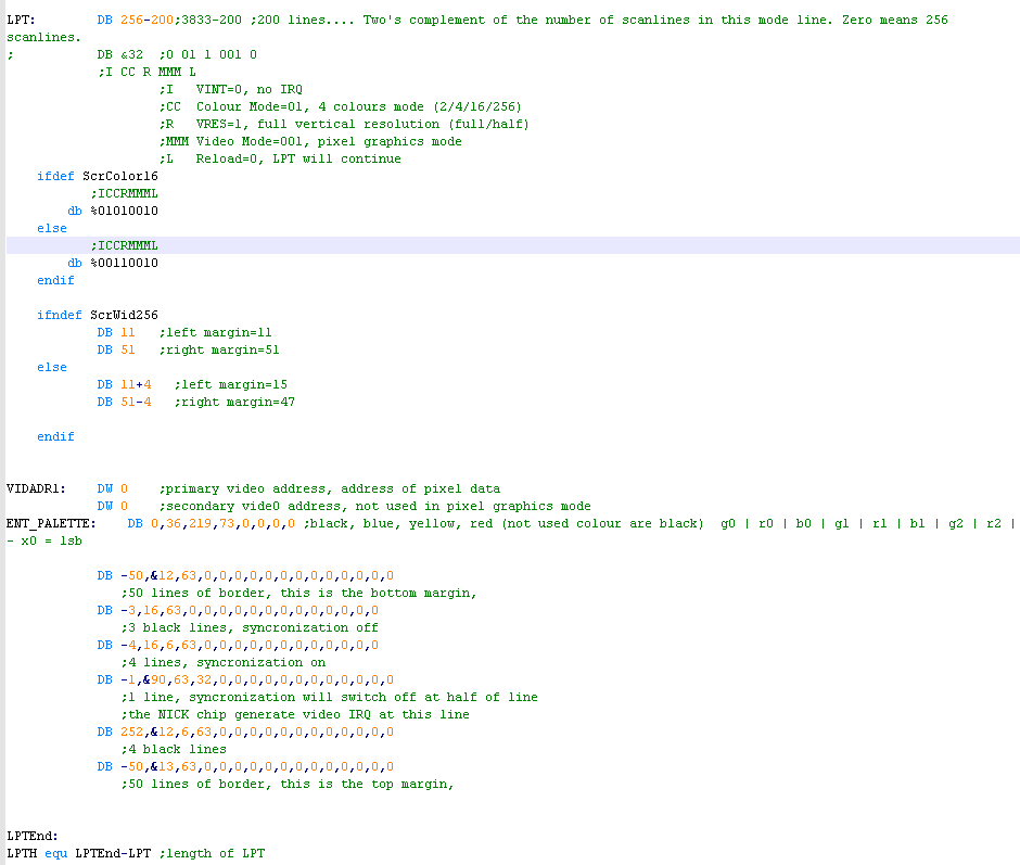 |
| Offset | Name | Bytes | Example | Meaning | |
| 0 | SC | 1 | 256-200 | LLLLLLLL | Two's complement of the number of scanlines in this mode line.
Zero means 256 scanlines. |
| 1 | MB | 1 | %01010010 | ICCRMMML | I VINT=0, no IRQ CC Colour Mode=01, 4 colours mode (2/4/16/256) R VRES=1, full vertical resolution (full/half) MMM Video Mode=001, pixel graphics mode L Reload=0, LPT will continue |
| 2 | LM | 1 | 11 | SSLLLLL | S Special bits in 2 color mode L Left Margin |
| 3 | RM | 1 | 51 | SSRRRRR | S Special bits in 2 color mode R Right Margin |
| 4 | VIDADDR | 2 | &0000 | LLLLLLL HHHHHHHH | Memory address of Vram in first 64k of memory (low number banks - not 128k upgrade) |
| 6 | VIDADDR2 | 2 | ? | LLLLLLL HHHHHHHH | Second Video Data address - not used in pixel graphics Modes |
| 8 | COL0-7 | 1x8 | %00000111 | g0 r0 b0 g1 r1 b1 g2 r2 | 8 palette definitions (8-15 are the same, with FIXBIAS offset) |
| 16 | SC | - | - | - | Next line in the LPT block |
Enterprise Screen bit layout
The pixel bits are in different orders,
depending on screen mode.
In the chart below: Numbers are the bit number, A-Z are the pixels
contained in the byte.
| 2 color Mode Bits/Pixels |
A |
B |
C |
D |
E |
F |
G |
H |
| 4 color Mode Bits/Pixels | A0 | B0 | C0 | D0 | A1 | B1 | C1 | D1 |
| 16 color Mode Bits/Pixels | A0 | B0 | A2 | B2 | A1 | B1 | A3 | B3 |
Keyboard/Joystick
Reading from the keyboard on the
enterprise is easy.
There are 10 rows, from 0-9, we just send the number of the row we want to
port &B5, we then read in from port &B5 to get the status of the
keys in that row.
Reading the Joystick in is also done from port &B5 , however to select the row we use port &B6.
| Row OUT &B5 |
IN &B5 | IN &B6 | |||||||||
| bit 7 | bit 6 | bit 5 | bit 4 | bit 3 | bit 2 | bit 1 | bit 0 | bit 2 | bit 1 | bit 0 | |
| 0 | LShift | Z | X | V | C | B | \ | N | J1-F3 | J1-F2 | J1-F1 |
| 1 | Ctrl | A | S | F | D | G | Lock | H | J1-U | ||
| 2 | Tab | W | E | T | R | Y | Q | U | J1-D | ||
| 3 | Esc | 2 | 3 | 5 | 4 | 6 | L | 7 | J1-L | ||
| 4 | F1 | F2 | F7 | F5 | F6 | F3 | F8 | F4 | J1-R | ||
| 5 | Erase | ~ | 0 | - | 9 | 8 | J2-F3 | J2-F2 | J2-F1 | ||
| 6 | ] | : | L | ; | K | J | J2-U | ||||
| 7 | ALT | Enter | Left | Hold | Up | Right | Down | Stop | J2-D | ||
| 8 | INS | Space | Rshift | . | / | , | Delete | M | J2-L | ||
| 9 | [ | P | @ | O | I | J2-R | |||||
General
Ports on the Enterprise (&80-&83=NICK)
| Port | Purpose | Bits | Bit Meaning |
| &80 | Fixbias (Color 8-15 top bits) | %----GRBGR | Top 5 bits of
color 8-16 (bottom BGR bits are 000,001,010 etc up to 111) |
| &81 | Border
Color |
Eight bit colour value which will be displayed outside the margins of all mode lines.(%GRBGRBGR) | ;g0 |
r0 | b0 | g1 | r1 | b1 | g2 | r2 | - x0 = lsb |
| &82 | LPL � Line Paramater Table Low Byte | Low part (A4..A11) of the line parameter base pointer.(%AAAAAAAA) | A=Address
bits 11-4 |
| &83 | LPH � Line Paramater Table High Byte | High part of the line parameter base pointer.(%LC--AAAA) | A=Address
bits 15-12 , L=Load base C=Clock in line |
| &B0 | Ram page 0 (0000-4000) | ||
| &B1 | Ram page 1 (4000-8000) | ||
| &B2 | Ram page 2 (8000-C000) | ||
| &B3 | Ram page 3 (C000-FFFF) | ||
| &B4 | Interrupt latches | ||
| &B5 | Select keyboard/joy row (out) | ||
| &B5 | read keyboard row (in) | ||
| &B6 | Read Joy row (in) | ||
| &B7 | WR2 / RD2 (in/out) | ||
| &BF | Ram options (out) (&0C = fast) |
Sound ports on the Enterprise (DAVE)
| Port | Purpose | Bits | Bit Meaning |
| &A0 | Channel 0 Tone L | LLLLLLLL | L=Tone Low Byte� Lower values=Higher tone |
| &A1 | Channel 0 Tone H | RPCCHHHH | H=Tone High Bits / polynomial Counter / Ring Modulator (CH2) / highPass Filter (CH1) |
| &A2 | Channel 1 Tone L | LLLLLLLL | L=Tone Low Byte� Lower values=Higher tone |
| &A3 | Channel 1 Tone H | RPCCHHHH | H=Tone High Bits / polynomial Counter / Ring Modulator (CHN) / highPass Filter (CH2) |
| &A4 | Channel 2 Tone L | LLLLLLLL | L=Tone Low Byte� Lower values=Higher tone |
| &A5 | Channel 2 Tone H | RPCCHHHH | H=Tone High Bits / polynomial Counter / Ring Modulator (CH0) / highPass Filter (CHN) |
| &A6 | Noise Channel frequency | RHLBCCNN | Noise (0=31khz 1-3=Channel 0-2 link) / polynominal Counter/ swap Bits 7 & 17 of pc / Lowpass /Highpass / Ring modulator |
| &A7 | Sync & Interrupt rate | -IIDDSSS | Interrupts (0=1khz,1=50hz,2=tone0,3=tone1) D=D/A ladder on (speccy 48k emu) / Sync for tone 0,1,2 (1=hold 0=run) |
| &A8 | Tone Channel 0 LH Amplitude | --VVVVVV | V=Volume(63=max) D/A ladder (If &A7 Bit3=1... tape port, Speaker L) |
| &A9 | Tone Channel 1 LH Amplitude | --VVVVVV | V=Volume(63=max) |
| &AA | Tone Channel 2 LH Amplitude | --VVVVVV | V=Volume(63=max) |
| &AB | Noise Channel LH Amplitude | --VVVVVV | V=Volume(63=max) |
| &AC | Tone Channel 0 RH Amplitude | --VVVVVV | V=Volume(63=max)
D/A ladder (If &A7 Bit4=1... tape port, Speaker R) |
| &AD | Tone Channel 1 RH Amplitude | --VVVVVV | V=Volume(63=max) |
| &AE | Tone Channel 2 RH Amplitude | --VVVVVV | V=Volume(63=max) |
| &AF | Noise Channel RH Amplitude | --VVVVVV | V=Volume(63=max) |
EXOS (RST 6 / RST 6*8) functions
| Function
|
Meaning | IN Param A | IN Params (other) | OUT Result A
|
Out Params (other) |
| 0 | System Reset | C=Reset type flags | Status | ||
| 1 | Open Channel | Channel Number | Status | ||
| 2 | Create Channel | Channel Number | Status | ||
| 3 | Close Channel | Channel Number | Status | ||
| 4 | Destroy Channel | Channel Number | Status | ||
| 5 | Read Character | Channel Number | Status | B=Character | |
| 6 | Read Block | Channel Number | BC=Byte Count DE=Buffer Address | Status | BC=Bytes left to read DE=Modified buffer address |
| 7 | Write Character | Channel Number | B=Character | Status | |
| 8 | Write Block | Channel Number | BC=Byte Count DE=Buffer Address | Status | BC=Bytes left to write DE=Modified buffer address |
| 9 | Channel Read Status | Channel Number | Status | C=Status (0=Ready -1=EOF 01=otherwise) | |
| 10 | Set and Read channel status | Channel Number | C=Write Flags DE=Parameter block | Status | C=Read Flags |
| 11 | Special Function | Channel Number | B=Subfunction Number C+DE=Unspecified | Status | C+DE=Unspecified |
| 12 | |||||
| 13 | |||||
| 14 | |||||
| 15 | |||||
| 16 | Read,Write or Toggle EXOS variable | B=Action
(0=Read 1=Write 2=Toggle) C=ExosVar number D=NewValue |
Status | D=New value | |
| 17 | Capture Channel | Main Channel number | C=Secondary channel number | Status | |
| 18 | Redirect Channel | Main Channel number | C=Secondary channel number | Status | |
| 19 | Set default device name | DE=Device name pointer C=Device type | Status | ||
| 20 | Return System Status | DE=Parameter block | Status | B=Version number | |
| 21 | Link Device | DE=Pointer to Device descriptor BC=Ram Required | Status | ||
| 22 | Read EXOS Boundary | Status | C=Shared Seg number DE=EXOS boundary in seg | ||
| 23 | Set User Boundary | DE=Offset of user boundary in seg | Status | ||
| 24 | Allocate segment | Status | C=Segment number DE=EXOS boundary in seg | ||
| 25 | Free segment | C=Segment | Status | ||
| 26 | Scan System extensions | DE=Pointer to command string | Status | ||
| 27 | Allocate channel buffer | DE=Amount of buffer in one seg BC=amount of buffer which can be in multiple segs | Status | IX=Allocated bufer Page1=New buffer seg | |
| 28 | Explain Error code | Error Code | DE=String buffer | 0 | |
| 29 | Load Module | DE=Buffer B=Channel to load from | Status | B=1st char / Module type / undefined | |
| 30 | Load relocatable module | B=Channel number DE=Starting address to load at | Status | ||
| 31 | Set time | C=HH D=MM E=SS (BCD) | Status | ||
| 32 | Read Time | Status | C=HH D=MM E=SS (BCD) | ||
| 33 | Set Date | C=YY D=MM E=DD (BCD) | Status | ||
| 34 | Read Date | Status | C=YY D=MM E=DD (BCD) |
For full details See page 50: EXOS20_technical_information.pdf
EXOS Variables
Use with EXOS call 16 (set C to var number)
| Var |
Name | Description |
| 0 | IRQ_ENABLE_STATE | |
| 1 | FLAG_SOFT_IRQ | |
| 2 | CODE_SOFT_IRQ | |
| 3 | DEF_TYPE | Type of default Device (0=NonFile 1=File) |
| 4 | DEF_CHAN | Default channel number (used when 255 specified) |
| 5 | TIMER | 1hz |
| 6 | LOCK_KEY | Keyboard lock status |
| 7 | CLICK_Key | 0=enabled |
| 8 | STOP_IRQ | 0=Stop causes IRQ >0=Stop returns code |
| 9 | KEY_IRQ | 0=Any key causes soft IRQ |
| 10 | RATE_KEY | in 1/50 of a second |
| 11 | DELAY_KEY | 0=no autorepeat |
| 12 | TAPE_SND | 0=Sound enabled |
| 13 | WAIT_SND | 0=sound driver waits when queue full |
| 14 | MUTE_SND | 0=Speaker enabled >0=Speaker disabled |
| 15 | BUF_SND | Sound envelope storage in phases |
| 16 | BAUD_SER | Baud serial rate |
| 17 | FORM_SER | Serial word format |
| 18 | ADDR_NET | Network address of machine |
| 19 | NET_IRQ | 0=Data received causes IRQ |
| 20 | CHAN_NET | Channel number of net block received |
| 21 | MACH_NET | Source machine of network block |
| 22 | MODE_VID | Video Mode (On page open) |
| 23 | COLR_VID | Color Mode (On page open) |
| 24 | X_SIZ_VID | X page size (On page open) |
| 25 | Y_SIZ_VID | Y page size (On page open) |
| 26 | ST_Flag | 0=Status line displayed |
| 27 | BORD_VID | Border color (%GRBGRBGR) |
| 28 | BIAS_VID | Color Bias for palette colors 8-16 (%----GRBGR) |
| 29 | VID_EDIT | Channel number of video page for editor |
| 30 | KEY_EDIT | Channel number of Ketboard for editor |
| 31 | BUF_EDIT | Size of edit buffer (in 256 byte pages) |
| 32 | FLG_EDIT | Flags to control reading from editor |
| 33 | SP_TAPE | >0=Slow tape save |
| 34 | PROTECT | >0=Write protected file |
| 35 | LV_TAPE | Tape output level |
| 36 | REM1 | State of Tape remote controls (0=on >0=off) |
| 37 | REM2 | State of Tape remote controls (0=on >0=off) |
Enterprise Programming Tutorials:
P3 - Bitmap graphics on the Amstrad CPC and Enterprise 128P7 - Keyreading on the MSX, Enterprise and TI-83
General Z80 Assembly Tutorials:
B. Beginner series - Learn the basicsA. Advanced series - In more detail
M. Multiplatform series - programming methods that work on all systems
Links
EP128emu - Enterprise Emulator - Set up guide
ep128.hu - great english enterprise 128 site
gafz enterprise forever site - another great english site
English Books for the EP128
Enterprise OS HTML documentation
Hello
World
Here's my Hello World example. I couldn't find one, so I had to
write it! It uses the operating system to access the screen and keyboard.
This code was tested using WinApe - which is a CPC emulator, but it
can compile ASM program code just fine
Download this from the sourcecode link at the top of this page!
| write "..\RelEnt\program.com" ;;;;;;;;;;;;;;;;;;;;;;;;;;;;;;;;;;;;;;;;;;;;;;;;;;;;;;;;;;;;;;;; ; Hello World ; ; Show a hello world message, then read a key ; From the keyboard and show it. ; ; Screen and keyboard ops use Enterprise OS calls ; by opening 'stream' devices to the Keyboard and ; screen ; ;;;;;;;;;;;;;;;;;;;;;;;;;;;;;;;;;;;;;;;;;;;;;;;;;;;;;;;;;;;;;;;; ORG &00F0 DB0,5 ;type 5 - Binary Program DW FileEnd-FileStart ;File length DB 0,0,0,0,0,0,0,0,0,0,0,0 ;Spacer ; org &0100 FileStart: LD SP,&100 ;set the Stack to a safe place di ld c,MODE_VID ;Set text mode ld d,0 call ENT_Writevar ld c,COLR_VID ;Set 2 color ld d,0 call ENT_Writevar ld c,X_SIZ_VID ; 40 Chars Wide ld d,40 call ENT_Writevar ld c,Y_SIZ_VID ;24 chars tall ld d,24 call ENT_Writevar ld de,ENT_Screenname ;Open Screen as stream 10 ld a,10 call ENT_OpenStream ;Display the just opened screen ld a,10 ; A channel number (1..255) ld b,1 ; B @@DISP (=1) (special function code) ld c,1 ; C 1st row in page to display (1..size) ld d,24 ; D number of rows to display (1..27) ld e,1 ; E row on screen where first row should appear (1..27) call ENT_SpecialFunc ld de,ENT_Keboardname ; Open the keyboard as stream 11 ld a,11 call ENT_OpenStream ;;;;;;;;;;;;;;;;;;;;;;;;;;;;;;;;;;;;;;;;;;;;;;;;;;;;;;;;;;;;;;;; ; INIT Done ;;;;;;;;;;;;;;;;;;;;;;;;;;;;;;;;;;;;;;;;;;;;;;;;;;;;;;;;;;;;;;;; ld hl,Message call PrintString ;Print Hello world message call NewLine call WaitChar ;Wait for a keypress push af ld hl,Message2 ;Print 'You Pressed' message call PrintString pop af call PrintChar ;print the char the user pressed call NewLine di halt ;stop execution - I've not figured out how to return to basic! Message: db 'Hello World!',255 Message2: db 'Key Pressed:',255 PrintString: ld a,(hl) cp 255 ret z inc hl call PrintChar jr PrintString ;;;;;;;;;;;;;;;;;;;;;;;;;;;;;;;;;;;;;;;;;;;;;;;;;;;;;;;;;;;;;;;; ; Functions for controling EXOS ;;;;;;;;;;;;;;;;;;;;;;;;;;;;;;;;;;;;;;;;;;;;;;;;;;;;;;;;;;;;;;;; MODE_VID equ 22 ;Enterprise OS variable numbers COLR_VID equ 23 X_SIZ_VID equ 24 Y_SIZ_VID equ 25 ENT_OpenStream: ;Open stream A from device string DE ;DE should point to a string like... db 6,'VIDEO;' or db 9,'KEYBOARD;' (replace ; with a colon) rst 6 db 1 ;open stream ret WaitChar: push de push hl push bc ld a,11 rst 6 db 5 ;read from channel - result in b ld a,b pop bc pop hl pop de ret PrintChar: push de push hl push bc ld b,a ld a,10 rst 6 db 7 ;write to channel a pop bc pop hl pop de ret NewLine: ld a,13 call PrintChar ld a,10 call PrintChar ret ENT_readvar: ;readvar C from enterprise OS ld b,0 rst 6 db 16 ret ENT_Writevar: ;WriteVar C=D to Enterprise OS ld b,1 rst 6 db 16 ret ENT_SpecialFunc: ;Special Function (for displaying screen) rst 6 db 11 ret ;Device names db [length],'name;' ENT_Screenname: db 6,'VIDEO:' ENT_Keboardname: db 9,'KEYBOARD:' ;;;;;;;;;;;;;;;;;;;;;;;;;;;;;;;;;;;;;;;;;;;;;;;;;;;;;;;;;;;;;;;; FileEnd: |
Starting the program: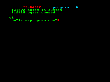 The program will show hello world, then pause for a keypress 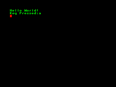 |
| View Options |
| Default Dark |
| Simple (Hide this menu) |
| Print Mode (white background) |
| Top Menu |
| ***Main Menu*** |
| Youtube channel |
| Patreon |
| Introduction to Assembly (Basics for absolute beginners) |
| Amazon Affiliate Link |
| AkuSprite Editor |
| ChibiTracker |
| Dec/Bin/Hex/Oct/Ascii Table |
| Alt Tech |
| Archive.org |
| Bitchute |
| Odysee |
| Rumble |
| DailyMotion |
| Please note: I wlll upload more content to these alt platforms based on the views they bring in |
| 68000 Content |
| ***68000 Tutorial List*** |
Learn 68000 Assembly  |
| Hello World Series |
| Platform Specific Series |
| Simple Samples |
| Grime 68000 |
| 68000 Downloads |
| 68000 Cheatsheet |
| Sources.7z |
| DevTools kit |
| 68000 Platforms |
| Amiga 500 |
| Atari ST |
| Neo Geo |
| Sega Genesis / Mega Drive |
| Sinclair QL |
| X68000 (Sharp x68k) |
| 8086 Content |
| Learn 8086 Assembly |
| Platform Specific Series |
| Hello World Series |
| Simple Samples |
| 8086 Downloads |
| 8086 Cheatsheet |
| Sources.7z |
| DevTools kit |
| 8086 Platforms |
| Wonderswan |
| MsDos |
| ARM Content |
| Learn ARM Assembly |
| Learn ARM Thumb Assembly |
| Platform Specific Series |
| Hello World |
| Simple Samples |
| ARM Downloads |
| ARM Cheatsheet |
| Sources.7z |
| DevTools kit |
| ARM Platforms |
| Gameboy Advance |
| Nintendo DS |
| Risc Os |
| Risc-V Content |
| Learn Risc-V Assembly |
| Risc-V Downloads |
| Risc-V Cheatsheet |
| Sources.7z |
| DevTools kit |
| MIPS Content |
| Learn Risc-V Assembly |
| Platform Specific Series |
| Hello World |
| Simple Samples |
| MIPS Downloads |
| MIPS Cheatsheet |
| Sources.7z |
| DevTools kit |
| MIPS Platforms |
| Playstation |
| N64 |
| PDP-11 Content |
| Learn PDP-11 Assembly |
| Platform Specific Series |
| Simple Samples |
| PDP-11 Downloads |
| PDP-11 Cheatsheet |
| Sources.7z |
| DevTools kit |
| PDP-11 Platforms |
| PDP-11 |
| UKNC |
| TMS9900 Content |
| Learn TMS9900 Assembly |
| Platform Specific Series |
| Hello World |
| TMS9900 Downloads |
| TMS9900 Cheatsheet |
| Sources.7z |
| DevTools kit |
| TMS9900 Platforms |
| Ti 99 |
| 6809 Content |
| Learn 6809 Assembly |
| Learn 6309 Assembly |
| Platform Specific Series |
| Hello World Series |
| Simple Samples |
| 6809 Downloads |
| 6809/6309 Cheatsheet |
| Sources.7z |
| DevTools kit |
| 6809 Platforms |
| Dragon 32/Tandy Coco |
| Fujitsu FM7 |
| TRS-80 Coco 3 |
| Vectrex |
| 65816 Content |
| Learn 65816 Assembly |
| Hello World |
| Simple Samples |
| 65816 Downloads |
| 65816 Cheatsheet |
| Sources.7z |
| DevTools kit |
| 65816 Platforms |
| SNES |
| eZ80 Content |
| Learn eZ80 Assembly |
| Platform Specific Series |
| eZ80 Downloads |
| eZ80 Cheatsheet |
| Sources.7z |
| DevTools kit |
| eZ80 Platforms |
| Ti84 PCE |
| IBM370 Content |
| Learn IBM370 Assembly |
| Simple Samples |
| IBM370 Downloads |
| IBM370 Cheatsheet |
| Sources.7z |
| DevTools kit |
| Super-H Content |
| Learn SH2 Assembly |
| Hello World Series |
| Simple Samples |
| SH2 Downloads |
| SH2 Cheatsheet |
| Sources.7z |
| DevTools kit |
| SH2 Platforms |
| 32x |
| Saturn |
| PowerPC Content |
| Learn PowerPC Assembly |
| Hello World Series |
| Simple Samples |
| PowerPC Downloads |
| PowerPC Cheatsheet |
| Sources.7z |
| DevTools kit |
| PowerPC Platforms |
| Gamecube |
| Work in Progress |
| ChibiAndroids |
| Misc bits |
| Ruby programming |
Buy my Assembly programming book
on Amazon in Print or Kindle!


Available worldwide!
Search 'ChibiAkumas' on
your local Amazon website!
Click here for more info!


Buy my Assembly programming book
on Amazon in Print or Kindle!
Available worldwide!
Search 'ChibiAkumas' on
your local Amazon website!
Click here for more info!
Buy my Assembly programming book
on Amazon in Print or Kindle!
Available worldwide!
Search 'ChibiAkumas' on
your local Amazon website!
Click here for more info!