Color
Palette
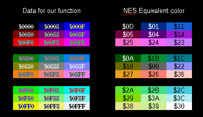
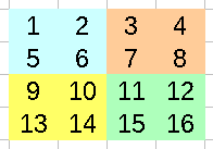
| The Nes palette is slightly odd
compared to RGB systems, you can see how the HEX values map to
colors in the chart to the right-> Each tile has 4 colors*, and you can have 4 separate palettes for tiles... and a separate 4 for sprites... this makes a total of 32 color definitions for tiles and sprites combined * Though the background colors are common to all sprites. |
|
||||||||||||||||||||||||||||||||||||||||||||||||||||||||||||||||
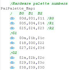
| Our Tutorials use a common format
on all platforms, where each channel is defined by one nibble in
$-GRB format... Because this doesn't easily map to the Nes palette, we'll convert it using a Lookup table of 3x3x3 size, so RGB values will go from 0-2 |
 |
| The NES
palette is a bit rigid, and doesn't really map to RGB very
well, but we've done what we can! If you don't like the mappings here, you can change the Lookup Table, or write your own native code. |
 |
Vram Layout
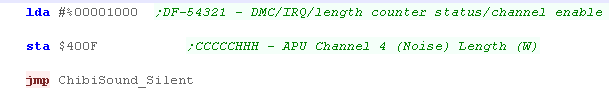
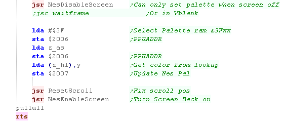
| While Pattern data is defined by
the Name Table, the Attribute Table defines the Color By default the NES has too little VRAM to use Name/Attrib Table 2 & 3 Specify a memory address by writing the byte pair to $2006... HIGH BYTE FIRST... (Big Endian) NOTE: Writing to VRAM outside of VBLANK will cause problems... also note, selecting an address resets PPUSCROLL EG, lets point to $3F00... and write $11 to the first palette entry! lda #$3F ;High byte sta $2006 ;Send to vram select lda #$00 ;Low byte sta $2006 ;Send to vram select lda #$11 ;New value sta $2007 ;Send to write data |
* Extra Ram Only |
||||||||||||||||||||||||||||||||||||||||||
| Each palette on the NES has 3 colors -Background Color 0 is a common background color, and Color 0 in sprites transparent |
|
||||||||||||||||||||||||||||||||||||||||||
| The NES Name Table defines the Tilemap's patterns... one byte
per 8x8 tile defines the number of the tile... the name table is
32x30 tiles in size, so spans from $2000-$23BF Note: Name Table 2,3 ($2800-$3000) are not available on an standard NES , they will only be available if your cartridge has Extra Ram! Color's are defined by the 'Attribute table'... effectively, each square block of 2x2 tiles (16x16 pixels) have to use the same color palette... and each block of 4x4 tiles (32x32 pixels) are defined by a single byte (2 bits per block - for 4 possible palettes) Lets take the example to the right, with different 16 tiles making up a grid of 32x32 pixels- each areas palette would be defined by a single byte in the way below:
|
 |
 |
Unfortunately on the
NES, although our tiles are 8x8 pixel, our palette is defined at
a 16x16 level You'll notice objects in NES games (Such as ? blocks in mario) are usally 16x16 to ensure this isn't a problem. |
Our
Code
| We're going to use a 3x3x3
table of color conversions to convert our one nibble per
channel $-GRB definition to something valid for the NES Offset=(G*9)+(R*3)+B to calculate the color of the equivalent GRB color for the NES |
 |
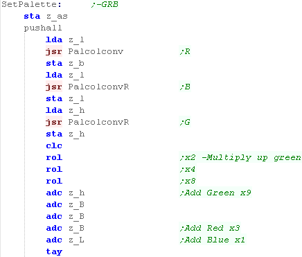
| When we call our SetPalette
function, we set A to the palette entry, and z_h and z_l as
the word defining the new color (in $-GRB format) We then want to calculate the palette entry, using the formula we just mentioned... We're going to use two functions One is 'PalcolConv' - which will take a high nibble, and convert it to a value 0-2.... The other is PalConvR - which will take the low nibble and do the same.... Once we've calculated the offset, we store it into Y |
 |
| We're going to need to load in the address of the lookup table into z_hl | 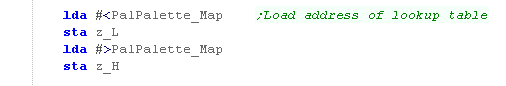 |
| We need to work out the correct
address to write to within the GTIA ($D016-D01A on the Atari
800 or $C016-C01A on the 5200) Color 0's address is $D01A Color 1's address is $D016 Color 2's address is $D017 Color 3's address is $D018 Once we've calculated the palette address to write to, we just output the new color we got from the lookup table to the destination address |
 |
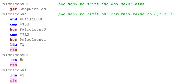
| Our palette conversion routines
use the following RGB conversions to convert a nibble to a
value 0-2 0-4...0 5-9...1 10-15...2 |
 |
 |
Lesson
P22 - Palette Definitions on the SNES / Super Famicom The Snes has 256 onscreen colors, and a superb 5 bits per channel RGB palette definition... lets learn how to use it! |
 |
 BmpTest.asm
|
|
 |
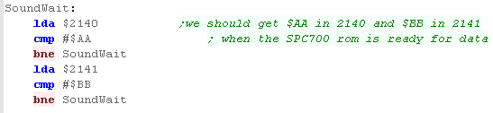
| Two ports are used to define the color on the SNES, the first
takes a single byte and selects the color we want to change, the second takes two bytes, and defines the new RGB color for that entry. |
|
||||||||||||||||||||||||||||||||||||||||||||||||||||||
| The 256 colors make up 16
palettes... the first 8 are used by Background patterns... the
second 8 are used by Sprites |
|
||||||||||||||||||||||||||||||||||||||||||||||||||||||
| In these tutorials, we a common format using one nibble per
color channel in the format $-GRB... The SNES uses 5 bits per channel in the format %-BBBBBGG GGGRRRRR We will need to convert our format to the correct format for the SNES! |
|
| The 255 onscreen
colors of the SNES are split between the Backgrounds and
Sprites, but the code will look at today will set background
and sprite colors at the same time. This will make things easier, and as we've only got 16 colors on most systems, we won't miss the extra colors in these tutorials! |
 |
Our
Code
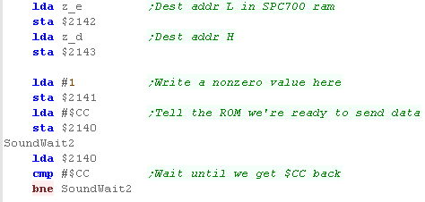
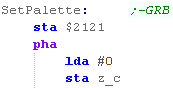
| When we call our SetPalette function, we set A to the palette
entry, and z_h and z_l as the word defining the new color (in
$-GRB format) We define the Color we're going to change by storing A in port $2121 We're going to use z_bc as a 'buildup' for the SNES format, so we need to clear z_c |
 |
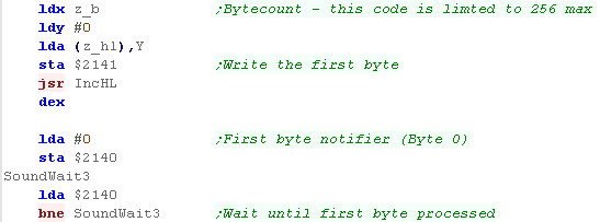
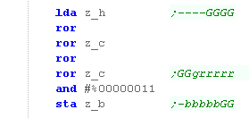
| We're going to first shift the Green component... We only have 4 bits in our definition, but the SNES uses 5, we'll shift two of the bits to the left into z_c, and store the top two bits into z_b |
 |
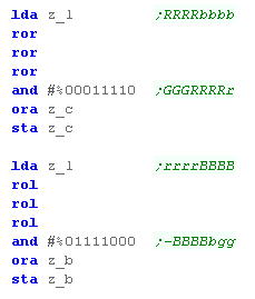
| We're going to shift the Red and
Blue bits as well, the correct format for the SNES is now in z_b and z_c |
 |
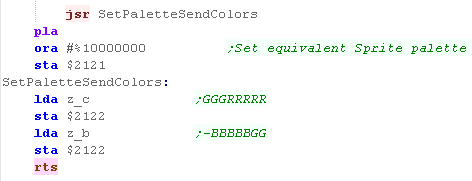
| To set the color we write the Low
byte from z_b to $2122, then we write the High byte from z_c
also to $2122 Once we've done the main color, we add 128 - and set the equivalent sprite color to the same color. |
 |