

Learn Multi platform 6502 Assembly Programming... For Monsters!
Platform Specific Lessons

 |
The SNES is
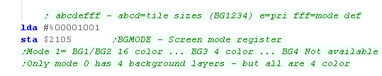
capable of up to 4 background layers, but only when all four are
in 4 color mode. We're using 3, allowing 2 to have 16 colors, and a third with just 4, which will give a good number of layers, with a nice set of colors!... If you want a different screen mode, it should be easy enough to tweak this example. |
Setup! 3 Tilemaps are
better than one!
| We're going to define a screen with three layers. We've got a 4 color layer which we won't move ( (though we could) we've got 2 16 color layers with 'Chibiko' bitmaps (the graphic uses 4 colors, but the layer is capable of 16!) All the graphics were created with AkuSprite Editor |
 |
| We're going to need to set up our screen! First we'll define the 'pattern addresses'... we're going to use the same bitmap data for all our layers (VRAM address $2000 in words) | 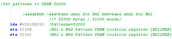 |
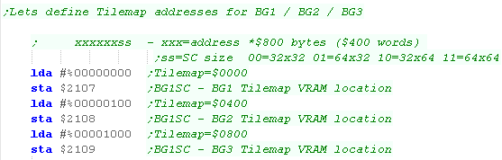
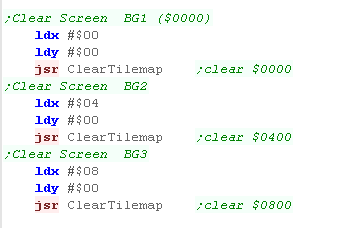
| While all the layers can share pattern data, they need different
tilemaps to define what is shown. We define three 32x32 tilemaps, at word addresses $0000,$0400 and $0800 |
 |
| We need to set up our screen mode - we're using Screen mode 3, and
defining all our tilemaps as using 8x8 tiles |
 |
Using our Tilemaps
| We're going to need to clear all our tilemaps! We'll create a function to zero each one.... setting all the tiles to tile zero (Vram address $2000) |
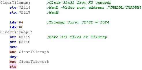 |
| We use this function to clear each tilemap separately |
 |
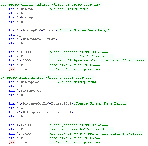
| We need to define the tiles for our two bitmaps. Strangely both will start from tile 128!?! How is this possible? Well, our tile patterns start from word address $2000, and 16 color tiles use 32 bytes per tile pattern.... so tile 128 is at address $2800, BUT... 4 color tiles use 16 bytes per tile pattern.... so tile 128 is at address $2400... This means we can have 'Chibiko' at 16 color tile 128+ ($2800) and 'Reida' at 4 color tile 128+ ($2400) |
 |
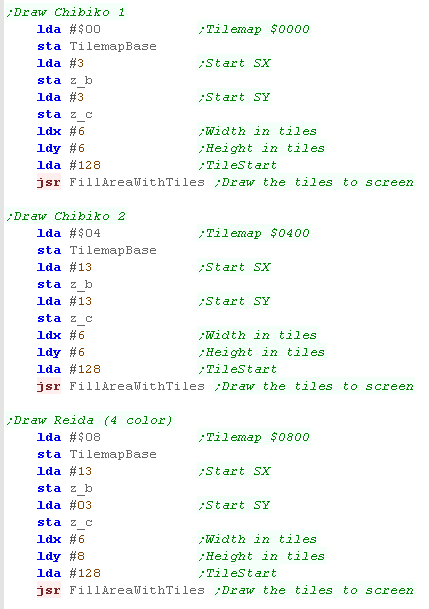
| We're using the same 'FillAreaWithTiles' as the simple series, We
just specify a 'TilemapBase' in the Zero page as the base of the
tilemap we're setting. |
 |
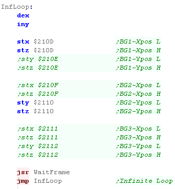
| We can scroll each layer using the registers from $210D+ Each controls the X or Y axis of a layer... each takes 2 bytes (16 bits), both bytes are written to the same port, Low byte then High byte. Here we're just using low bytes of the 16 bit pair. |
 |
The effects!
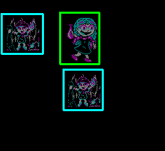
| We'll be trying a variety of effects today! We split our layers into 2 screens, the 'Main screen', and the 'Sub Screen'... the resulting colors are calculated from the two plus a calculation. Note the resulting 'calculated colors' are calculated by adding or subtracting the RGB values, not the palette entry numbers. We've got things set up so the 2 'Chibikos' are on the 'Main Screen'. the 1 'Reida' is on the sub screen |
 |
 |
 |
 |
 |
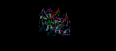
| Here we've calculated Main+Sub The colors gets brighter where the two overlap |
Here we've calculated Main-Sub Sub is hidden, and the colors gets darker where the two overlap |
Here we've calculated (Main+Sub)/2 The colors are blended (mixed) where the two overlap |
Here we've calculated Main+Sub however the sub screen maths does not apply to the background so is only visible when pixels of the other layers overlap |
Using the effects
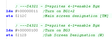
| First, We need to split our layers into the Main screen and the
Sub screen. We use $212C and $212D to do this... here we've put BG1+2 on the Main screen (The 2 Chibikos) and BG3 on the Sub screen (The 1 Reida) |
 |
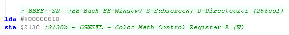
| We use $2130 to define how the color math applies to the window (a
mask we're not using) and the background color. We only want to enable the Sub screen - via bit 2 |
 |
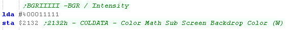
| We can configure a background color for the subscreen with
$2132... we've just set it to black |
 |
| all the rest of the work is done with $2131 - this selects the layers the SUB screen color maths affect, | 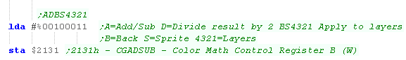 |
| Here we've performed Main+Sub | |
| By setting bit 7, we can perform subtraction. | 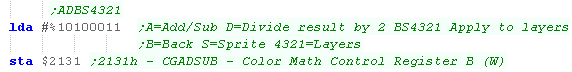 |
| Here we've performed Main-Sub | |
| By setting bit 6, we can divide the result by 2 | 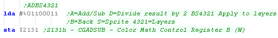 |
| Here we've performed (Main+Sub)/2 | |
| if we clear bit 5, the SUB screen does not show on the background - but still affects the BG1/BG2 layer! | 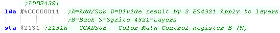 |
| Spooky! | |
| this time we've removed bit 1 - meaning the color maths doesn't affect BG2 | 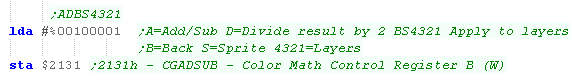 |
| Here the Left chibiko is affected by color maths, but the bottom one isn't! |  |
 |
The Color Maths of the SNES
give the SNES the ability for transparency effects that most other
16 bit systems couldn't achieve in hardware. Color effects can also be combined with 'Windows' which can be used to mask areas of the screen. The SNES has two windows, which we'll look at another time! |
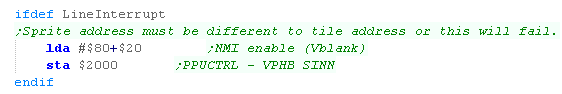
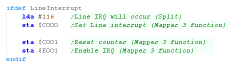
| For reasons best known to itself, the Mapper 3 line interrupt
requires the Sprite and Tile addresses to be different, we add $20
(Sprites VRam at $1000) to $80 (Vblank on) and write this to port
$2000 |
 |
| During NMI we need to set the line interrupt up... Here we've set it to occur on line 116... we write this to $C000 We also write any value to $C001 and $E001 to reset and start the interrupt |
 |
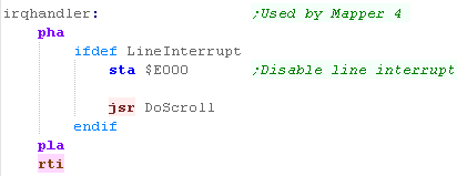
| The IRQ handler address needs to be stored at $FFFE in your
cartridge. The interrupt handler disables the IRQ with a write to $E000 - it's reset during the next vblank |
 |
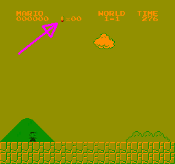
| Here's the result |  |
Hit me with your Sprite 0 Bit!
| The early NES games could not do line interrupts, but there's a
trick! Bit 6 of status port $2002 will be set to 1 the FIRST TIME* a pixel of sprite 0 hits a pixel of the background... this can be used to detect the current line. The pixel must be colored, and the sprite can be in front of, or behind the background. Super mario uses this to keep the score still, but scroll the play area... Sprite 0 is the bottom of the 'coin' and is 'hidden' below the one drawn on the tilemap! The Sprite0Hit does not cause an interrupt, so we need to check for it in software. *Note... The bit does not clear until AFTER the next Vblank, so this can only be done once per screen... also note that the bit does not clear until the END of VBLANK, so if our NMI routine is short, it may end before the bit is cleared, which could cause problems if we immediately test for the bit being set again. |
 |
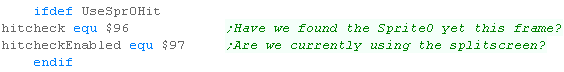
| We're going to define two variables... We'll need to turn off the
split during setup and the like - hitcheckEnabled does this. Our 'Detection' routine will be in the main loop, but once we've found Sprite0 this line we'll stop checking, 'hitcheck' will do this |
 |
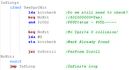
| During our main loop, we'll check 'HitCheck' - If it's nonzero
(%01000000), we AND this with $2002 to test the Sprite0Hit bit. When this is nonzero we do our scroll... we then set HitCheck to zero, so we don't check again until the next frame. |
 |
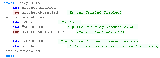
| During the Vblank NMI we need to reset the HitCheck, but the
Sprite0Hit bit (bit 6 of $2002) doesn't clear until the END of
Vblank... if our NMI routine is short, the mainloop may run
again before it clears. To solve this we wait for bit 6 of $2002 to clear before we return, so the Sprite0Hit flag will only be set again once the sprite is drawn. |
 |
| Here is the result! |  |
Horizontal split screen scroll
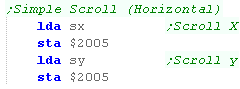
| Horizontal scroll is easy, we just write two new scroll bytes to
$2005. This will set the X scroll fine, but unfortunately the Y-scroll is ignored, as the hardware only properly responds during a new screen redraw. |
 |
| Here is a Horizontal scroll | |
Vertical split screen scroll
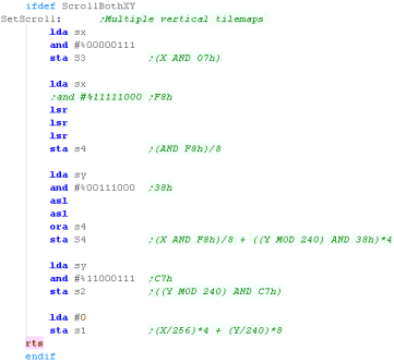
| Vertical (or Horizontal+Vertical) scrolling is more tricky, but by calculating the 4 correct values, and writing them | 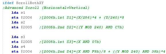 |
| The formulas for the 4 writes are: [2006h.1st S1]=(X/256)*4 + (Y/240)*8 [2005h.2nd S2]=((Y MOD 240) AND C7h) [2005h.1st S3]=(X AND 07h) [2006h.2nd S4]=(X AND F8h)/8 + ((Y MOD 240) AND 38h)*4 |
 |
| Here is a 2 direction scroll. | |
| As the author of
these tutorials is a bit of a thicky, The formulas above were
taken from the 'EveryNes'
documentation! While these tutorials are the best the author can do... Please see that far better document for more info on split screen scrolling!!! |
 |
 |
Lesson
P44 - The NES Zapper! The NES has a Lightgun... it detects light, and is also a gun! Let's lock and load, and learn how to zap us some chibis! |
 |
 NES_Zapper.asm
|
 |
| This lesson assumes
you know how to set tiles on the tilemap, and do hardware
sprites... or you're going to figure it out yourself... or you simply don't care how to do anything! Check out the other NES tutorials on this site... Sorry for the extra work, but we can't explain the whole program every single tutorial!! |
 |
The Light Gun... a light sensor, a trigger and nothing else!
| Lightguns are typically pretty simple... there's a light sensor at
the front with a lens, and a trigger for us to shoot. All the work has to be done by us, we have to flash parts of the screen black and white to work out what the gun is pointing at. Super smart lightguns (Like the SNES and SMS one) can spot the exact pixel the gun is pointing at as the screen raster redraws... then NES light gun is NOT one of those! Reading the gun is easy, we read in from the Joystick port and check two bits, one for the trigger, and one for the light sensor |
|
|
Todays example is
programmed for a lightgun on Port 2... you can change $4017 to $4016
if you want to use Port 1 It's been tested with the Nestopia emulator... Your mileage may vary with other emulators. |
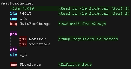
Reading the Lightgun
| Here the lightgun is shown in the A register. If we press fire bit 4 will change to 1 ($48 -> $58) The gun reads light even when fire isn't pressed... we'll see bit 3 change to 0 ($48 -> $40) Notice that the 'Light' bit flickers on and off when pointing at the light, this is because the 'raster beam' is constantly moving, and the screen is flickering faster than our eyes can see (and emulator emulates) |
 |
| The trouble is, the lightgun is so dumb it'll detect our text, or
even the lighbulb of a cheating player!... we therefore need to
black the screen, Test, then illuminate the screen to check if the
player's pointing at a target. To get around this we'll test and wait for a change... in later versions we'll take the minimum value during a loop... so if any light was seen during the frame, it is 'captured' in the result. |
 |
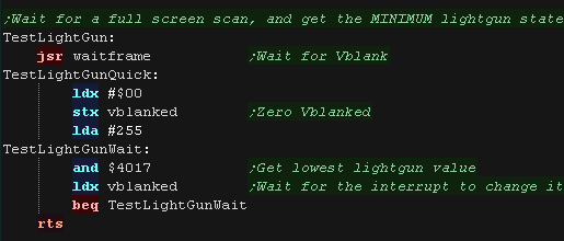
Detecting a target has been shot
| If we only have a simple "Duck hunt" style game with one or two
targets, we can use a simple reading routine: 1. Wait for the trigger to be pressed. 2. Blackout the screen, and test the light sensor... if the sensor sees light the gun isn't pointed at the screen (Give up) 3. White out one of the targets - if the gun sees light the player shot the target. 4. Repeat 3 for any other sprites. |
 |
| Here's our "New and improved" gun test routine. We wait for Vblank, to ensure the screens showing what we expect. We then scan the lightgun for a full frame, if at any point the gun saw light, we return that value in the accumulator |
 |
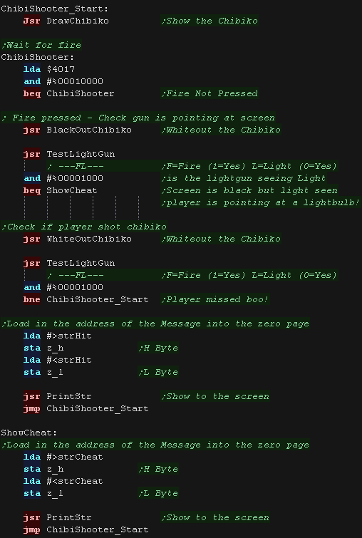
| Here's our example code for this procedure. This example uses the tilemap for graphics. We show "Hit" if the player shot chibiko. We show "Cheat" if light was seen when the screen should be black (You can test this by 'shooting' the text) |
 |
Detecting an X,Y position of the gun
| Super smart games like "Operation Wolf" are smarter than your
lowly Duck hunts When the trigger is pressed, the screen flashes white... and the game waits until the gun sees the white... counting the scanlines to work out the Y-position. The Nes is too slow to work out the Xpos in this way, so it shows sprites along the screen until the gun sees it to get the Xpos. |
 |
| We can do it too!*** Here' we're doing the same thing in the same way... we're so smart and original! |
 |
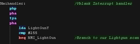
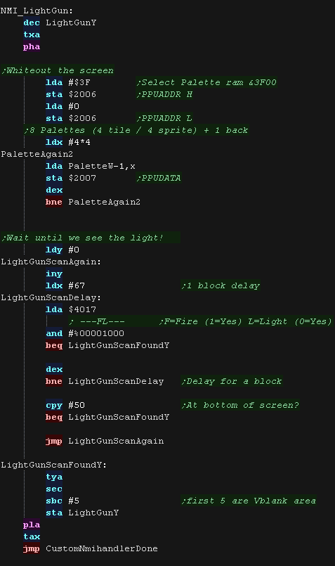
| our NMI will check the 'LightGunY'... We set this to 255 to flash
the screen, and check the Ypos. The scan involves flashing the screen, by switching the palette to one thats 'all white', we then count up, and wait until the light sensor sees the beam - That's our Y-Pos |
  |
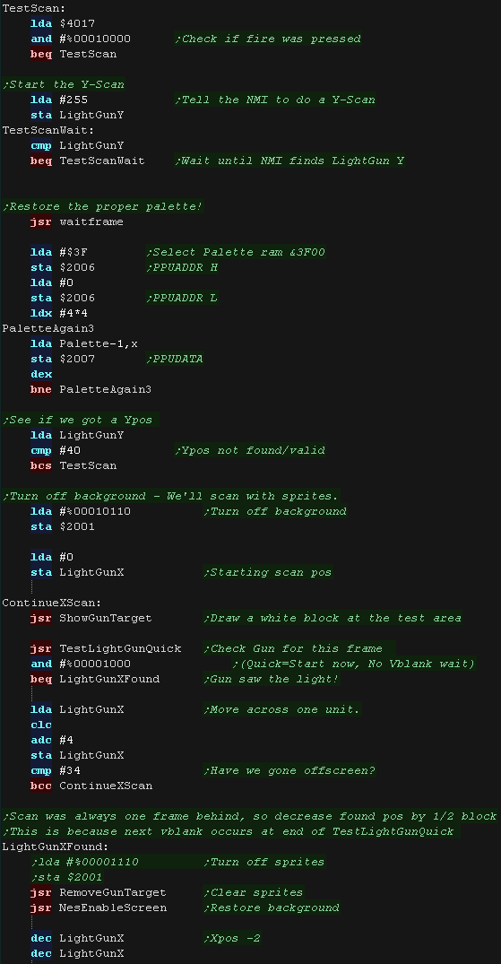
| We wait for fire to be pressed... Then we set the LightGunY to 255, This tells the NMI to do a scan. We wait for that scan to occur. OK, we've got our Y, but we now need to restore the proper palette! Next we're going to scan for the X-position.... we need to black out the screen, so we turn of the background tilemap, and just use sprites. We use a grid of 4x3 sprites to make a block... we put this on our known Ypos at the far left, and do a scan of the lightgun. If we didn't detect a hit, we move the block to the right, and repeat until the lightgun detects a hit (we now know our Xpos) - or the block reaches the end of the screen (The gun has moved?) |
 |
 |
*** OK we
haven't actually done as good a job as OpWolf! Notice there's two sprites moving along the screen on Opwolf?... well as soon as one of the two detects a hit, one disappears, and another test is done, so they can see which of the two was detected... they've effectively halved the scan time! Ah well... we've been out coded!... But this example isn't so bad either! |

ChibiSound PRO!
ChibiSound is the sound driver that handles the particularities of a system, there is typically one driver per system, though the CPC and MSX drivers are essentially identical except for the AY register setting routines.
The original 'ChibiSound' gave us one channel, one Volume bit, six pitch bits, and the ability to turn noise on. Pitches were not matched across systems, so sound 32 won't sound the same on all systems.
The updated 'ChibiSound Pro' gives us all the channels provided by the hardware, 8 volume bits, 16 pitch bits, and the ability to turn noise on. Pitches were not matched across systems, however the 'ChibiOctave' lookup table provides values which ARE matched across all systems.
ChibiSound PRO is essentially a reduced subset of AY functionality, and was designed on the Z80 - it's 'PRO' suffix is a parody of the 'SoundBlaster PRO' - which could only do 8 bit sound so wasn't up to professional standards! (neither is ChibiSound PRO)
ChibiSound PRO provides a standard interface to the underlying hardware, it allows the following features to be set for each channel on the underlying hardware:
| Function |
Zero page entry |
Notes: |
| Channel Number (bit 0-6) Noise On/Off (bit 7) |
H | Multiple channels can be supported, but on single channel systems
only Channel 0 will be sure to play. If possible Channel 0 will be a center channel, Channels 1+ may be left/right Noise bit turns the noise effect on (1) or off (0) - this can be set on any channel, if the underlying hardware only supports one noise channel, this will be resolved by the driver. |
| Volume | L | Set volume of the channel (0-255). Higher numbers are louder. O is off |
| Pitch | DE | Set the pitch of the channel (0-65535). Higher numbers are higher
pitch. Using DE does not standardize the resulting pitch - however a 'Lookup table' of notes 'ChibiOctave' provides a standardized way of getting the correct DE value to get a pitch correct note on the platform. |
| The
new driver is a big improvement on the old one but doesn't really
deserve the PRO suffix! It's a parody of the early 'Soundblaster Pro' sound cards, which could only do 8 bit digital sound, so weren't really of 'pro spec' either! |
|
Sound Controller - SN76489
The Sound Chip shares a port with the keybord... Before we can send any
data to the sound chip, we have to set the port to WRITE... we do this by
writing 255 to address $FE43 (we only do this once)
We've covered the sound chip in the Z80 tutorials here
Once we've done that, we can write our data to $FE41 in the format below
| Bits | |||||||||
| Command | Bit Details | 7 | 6 | 5 | 4 | 3 | 2 | 1 | 0 |
| Format Template | L=Latch C=Channel T=Type XXXX=Data | L | C | C | T | D | D | D | D |
| Tone - Command 1/2 | C=Channel L=tone Low data | 1 | C | C | 0 | L | L | L | L |
| Tone - Command 2/2 | H= High tone data (Higher numbers = lower tone) | 0 | - | H | H | H | H | H | H |
| Volume | C=Channel (0-2) V=Volume (15=silent 0=max) | 1 | C | C | 1 | V | V | V | V |
| Noise Channel | (Channel 3) M=Noise mode (1=white) R=Rate (3=use tone 2) | 1 | 1 | 1 | 0 | - | M | R | R |
 |
Chibisound PRO
requires each channel to be capable of noise, but the SN76489
sound chip only has one noise channel. We'll have to track the noise state for each 'virtual noise channel' and update the actual noise channel accordingly |
The ChibiSound Pro driver
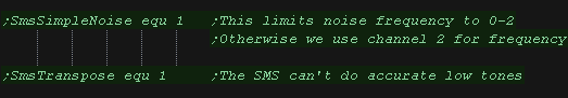
| The BBC/SMS driver has two options which can be enabled. SmsSimpleNoise: The SMS/BBC has two noise options, a noise pitch of 0-2, or a noise pitch set by channel 2 (losing a tone channel). We can enable this option to avoid using tone channel 2, or sacrifice tone functionality for better noise. SmsTranspose: The SMS/BBC can't produce accurate low tones, we have two options, use 'off tone' ones, or transpose everything up an octave. |
 |
| We need some ram to keep track of the nose state, and a lookup table for the 3 channels available to the hardware. | 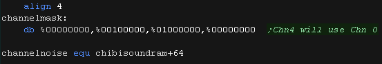 |
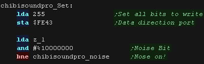
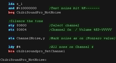
| Our first task is to set port $FE43 to write by writing 255. Next we check the noise bit of our passed L parameter and branch if needed |
 |
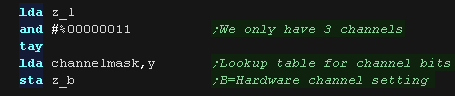
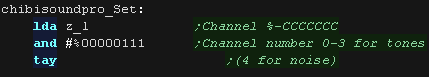
| We need to set bits 5-6 of our sound parameters to a channel
number. We may be passed a channel 0-127, so we use a 4 bit lookup table to 'map' these to actual channels 0-2 |
 |
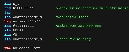
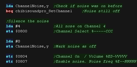
| The noise state may have changed, so we check the previous noise state, and see if we now need to
turn it off. If we do, we do so by setting the volume of channel 3 (noise) to 15 (silent) |
 |
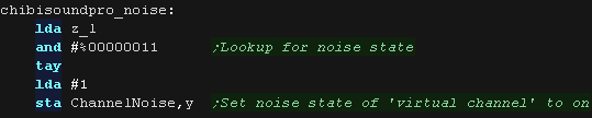
| if noise is on, we set the channels noise flag. |
 |
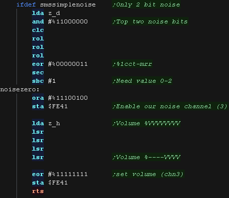
| If we're using simple noise, we need to set the volume of channel
3, and the bottom two bits of the frequency setting - which can only
take a value of 0-2 (3 sets it to use channel 2's frequency setting)
We're done, so we just return. |
 |
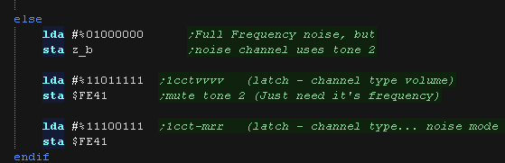
| If we're using advanced noise, we need to set the frequency of
channel 2, but the volume of channel 3 We set up the noise setting here - setting the rate to 3. |
 |
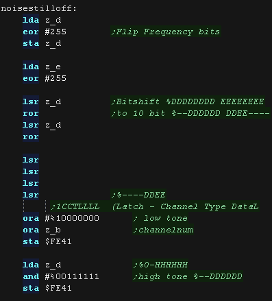
| First we set our frequency. The DE pair passes 16 bits, but we can only use 10, and we need to split those into 6 and 4 and send them to the hardware in two separate parts. |
 |
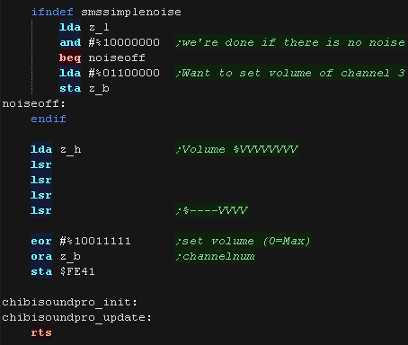
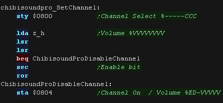
| If we're not using simple noise, we need to set the frequency of
channel 2, but the volume of
channel 3 We then shift the 8 volume bits into position to pass the 4 bits to the hardware. We also flip those bits, as on the hardware 15 is silent, and 0 is loudest. |
 |
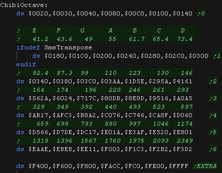
| The ChibiOctave lookup table provides matched notes which can be
loaded into DE to give consistent tones across all systems. Sharps and flats can be calculated by adding two values and dividing them by two. |
 |

ChibiSound PRO!
ChibiSound is the sound driver that handles the particularities of a system, there is typically one driver per system, though the CPC and MSX drivers are essentially identical except for the AY register setting routines.
The original 'ChibiSound' gave us one channel, one Volume bit, six pitch bits, and the ability to turn noise on. Pitches were not matched across systems, so sound 32 won't sound the same on all systems.
The updated 'ChibiSound Pro' gives us all the channels provided by the hardware, 8 volume bits, 16 pitch bits, and the ability to turn noise on. Pitches were not matched across systems, however the 'ChibiOctave' lookup table provides values which ARE matched across all systems.
ChibiSound PRO is essentially a reduced subset of AY functionality, and was designed on the Z80 - it's 'PRO' suffix is a parody of the 'SoundBlaster PRO' - which could only do 8 bit sound so wasn't up to professional standards! (neither is ChibiSound PRO)
ChibiSound PRO provides a standard interface to the underlying hardware, it allows the following features to be set for each channel on the underlying hardware:
| Function |
Zero page entry |
Notes: |
| Channel Number (bit 0-6) Noise On/Off (bit 7) |
H | Multiple channels can be supported, but on single channel systems
only Channel 0 will be sure to play. If possible Channel 0 will be a center channel, Channels 1+ may be left/right Noise bit turns the noise effect on (1) or off (0) - this can be set on any channel, if the underlying hardware only supports one noise channel, this will be resolved by the driver. |
| Volume | L | Set volume of the channel (0-255). Higher numbers are louder. O is off |
| Pitch | DE | Set the pitch of the channel (0-65535). Higher numbers are higher
pitch. Using DE does not standardize the resulting pitch - however a 'Lookup table' of notes 'ChibiOctave' provides a standardized way of getting the correct DE value to get a pitch correct note on the platform. |
| The
new driver is a big improvement on the old one but doesn't really
deserve the PRO suffix! It's a parody of the early 'Soundblaster Pro' sound cards, which could only do 8 bit digital sound, so weren't really of 'pro spec' either! |
|
SID sound chip
The SID chip uses memory addresses $D400-$D41C
| Address | Description | Bits | Meaning |
| $D400 | Voice #1 frequency L | LLLLLLLL | |
| $D401 | Voice #1 frequency H | HHHHHHHH | Higher values=higher pitch |
| $D402 | Voice #1 pulse width L | LLLLLLLL | |
| $D403 | Voice #1 pulse width H | ----HHHH | |
| $D404 | Voice #1 control register | NPST-RSG | Noise / Pulse / Saw-tooth / Triangle / - test / Ring mod / Sync /Gate |
| $D405 | Voice #1 Attack and Decay length | AAAADDDD | Attack / Decay (0=fastest) |
| $D406 | Voice #1 Sustain volume and Release length. | VVVVRRRR | Sustain Volume / Release (0=fastest) |
| $D407 | Voice #2 frequency L | LLLLLLLL | |
| $D408 | Voice #2 frequency H | HHHHHHHH | Higher values=higher pitch |
| $D409 | Voice #2 pulse width L | LLLLLLLL | |
| $D40A | Voice #2 pulse width H | ----HHHH | |
| $D40B | Voice #2 control register | NPST-RSG | Noise / Pulse / Saw-tooth / Triangle / - test / Ring mod / Sync /Gate |
| $D40C | Voice #2 Attack and Decay length | AAAADDDD | Attack /
Decay (0=fastest) |
| $D40D | Voice #2 Sustain volume and Release length. | VVVVRRRR | Sustain Volume / Release rate (0=fastest) |
| $D40E | Voice #3 frequency L | LLLLLLLL | |
| $D40F | Voice #3 frequency H | HHHHHHHH | Higher values=higher pitch |
| $D410 | Voice #3 pulse width L | LLLLLLLL | |
| $D411 | Voice #3 pulse width H | ----HHHH | |
| $D412 | Voice #3 control register. | NPST-RSG | Noise / Pulse / Saw-tooth / Triangle / - test / Ring mod / Sync /Gate |
| $D413 | Voice #3 Attack and Decay length. | AAAADDDD | Attack / Decay (0=fastest) |
| $D414 | Voice #3 Sustain volume and Release length. | VVVVRRRR | Sustain Volume / Release (0=fastest) |
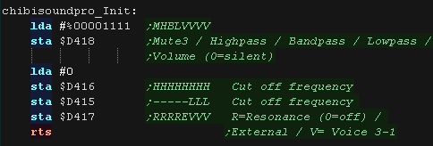
| $D415 | Filter cut off frequency L | -----LLL | Cut off
frequency |
| $D416 | Filter cut off frequency H | HHHHHHHH | Cut off frequency |
| $D417 | Filter control | RRRREVVV | R=Resonance (0=off) / External / V= Voice 3-1 |
| $D418 | Volume and filter modes | MHBLVVVV | Mute3 / Highpass / Bandpass / Lowpass / Volume (0=silent) |
| $D41B | Voice #3 waveform output. (Read only) | DDDDDDDD | |
| $D41C | Voice #3 ADSR output. (Read only) | DDDDDDDD |
|
We'll only be
using one kind of wave for our sounds (Pulse), as well as noise of
course! We'll use all 3 channels for our sound. |
The ChibiSound Pro driver
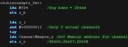
| We have 3 channels available to us, and the registers of these
have bases of $D400,$D407,$D40E We have a lookup table to select one of these depending on the passed channel number |
 |
| We need to set up some sound parameters once before we use the
driver. We set the general volume to max, and some of the other parameters to zero |
 |
| At the start of our setsound routine, we first select a sound
register set to use for the passed channel number. Our lookup table has 4 entries, so we read in using only the bottom two bits. Throughout this routine the BC pair in the zero page point to the registers for the channel. |
 |
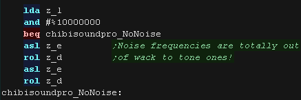
| We check the Noise bit. Frequencies for noise are very different to tones, so we bitshift the frequency a bit if noise is enabled. |
 |
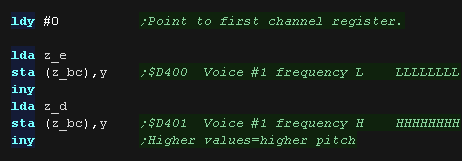
| We now set the frequency from the channel from D and E. Y is used to point to the sound register we're currently changing, we go through them in order. |
 |
| Next we set the Pulse length - this is needed for the pulse wave type. | 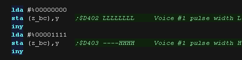 |
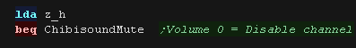
| We check the volume byte, if this is zero we need to silence the
channel. |
  |
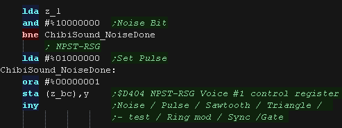
| If the top bit of L is 1, we need to enable Noise, Otherwise we use the Pulse tone |
 |
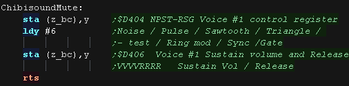
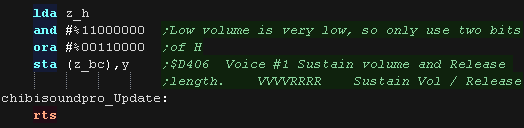
| We set the attack and delay to zero. This makes the tone start and stop instantly. | 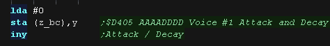 |
| Finally, we set the Volume. The C64 takes a 4 bit volume, but volumes <3 are very quiet, so we only use the top two bits of the H register. |
 |
ChibiSound PRO!
ChibiSound is the sound driver that handles the particularities of a system, there is typically one driver per system, though the CPC and MSX drivers are essentially identical except for the AY register setting routines.
The original 'ChibiSound' gave us one channel, one Volume bit, six pitch bits, and the ability to turn noise on. Pitches were not matched across systems, so sound 32 won't sound the same on all systems.
The updated 'ChibiSound Pro' gives us all the channels provided by the hardware, 8 volume bits, 16 pitch bits, and the ability to turn noise on. Pitches were not matched across systems, however the 'ChibiOctave' lookup table provides values which ARE matched across all systems.
ChibiSound PRO is essentially a reduced subset of AY functionality, and was designed on the Z80 - it's 'PRO' suffix is a parody of the 'SoundBlaster PRO' - which could only do 8 bit sound so wasn't up to professional standards! (neither is ChibiSound PRO)
ChibiSound PRO provides a standard interface to the underlying hardware, it allows the following features to be set for each channel on the underlying hardware:
| Function |
Zero page entry |
Notes: |
| Channel Number (bit 0-6) Noise On/Off (bit 7) |
H | Multiple channels can be supported, but on single channel systems
only Channel 0 will be sure to play. If possible Channel 0 will be a center channel, Channels 1+ may be left/right Noise bit turns the noise effect on (1) or off (0) - this can be set on any channel, if the underlying hardware only supports one noise channel, this will be resolved by the driver. |
| Volume | L | Set volume of the channel (0-255). Higher numbers are louder. O is off |
| Pitch | DE | Set the pitch of the channel (0-65535). Higher numbers are higher
pitch. Using DE does not standardize the resulting pitch - however a 'Lookup table' of notes 'ChibiOctave' provides a standardized way of getting the correct DE value to get a pitch correct note on the platform. |
| The
new driver is a big improvement on the old one but doesn't really
deserve the PRO suffix! It's a parody of the early 'Soundblaster Pro' sound cards, which could only do 8 bit digital sound, so weren't really of 'pro spec' either! |
|
The NES Sound Hardware
We'll need to use the ports $4000+ to control the sound hardware.
The ChibiTracks software want's 3 channels, so we'll use the two rectangle and triangle channels for general sound (even though it doesn't allow volume to be set), and the Noise channel when noise is required.
| Address | Purpose | Bits | Detail |
| 4000h | APU Channel 1 (Rectangle) Volume/Decay (W) | CCLEVVVV | Volume, Envelope Length counter,duty Cycle |
| 4001h | APU Channel 1 (Rectangle) Sweep (W) | EUUUDSSS | Sweep, Direction,Upadte rate, Enabled |
| 4002h | APU Channel 1 (Rectangle) Frequency (W) | LLLLLLLL | frequency L byte |
| 4003h | APU Channel 1 (Rectangle) Length (W) | CCCCCHHH | frequency H byte, length Counter load register |
| 4004h | APU Channel 2 (Rectangle) Volume/Decay (W) | CCLEVVVV | Volume, Envelope Length counter,duty Cycle |
| 4005h | APU Channel 2 (Rectangle) Sweep (W) | EUUUDSSS | Sweep, Direction,Upadte rate, Enabled |
| 4006h | APU Channel 2 (Rectangle) Frequency (W) | LLLLLLLL | frequency L byte |
| 4007h | APU Channel 2 (Rectangle) Length (W) | CCCCCHHH | frequency H byte, length Counter load register |
| 4008h | APU Channel 3 (Triangle) Linear Counter (W) | SLLLLLLL | L=Linear
Counter Load S=Start |
| 4009h | APU Channel 3 (Triangle) N/A (-) | -------- |
|
| 400Ah | APU Channel 3 (Triangle) Frequency (W) | LLLLLLLL | frequency L byte |
| 400Bh | APU Channel 3 (Triangle) Length (W) | CCCCCHHH | frequency H byte, length Counter load register |
| 400Ch | APU Channel 4 (Noise) Volume/Decay (W) | CCLEVVVV | Volume, Envelope Length counter,duty Cycle |
| 400Dh | APU Channel 4 (Noise) N/A (-) | ||
| 400Eh | APU Channel 4 (Noise) Frequency (W) | N---FFFF | N=Noise
type, F=Frequency |
| 400Fh | APU Channel 4 (Noise) Length (W) | CCCCC--- | length Counter load register |
| 4010h | APU Channel 5 (DMC) Play mode and DMA frequency (W) | ||
| 4011h | APU Channel 5 (DMC) Delta counter load register (W) | ||
| 4012h | APU Channel 5 (DMC) Address load register (W) | ||
| 4013h | APU Channel 5 (DMC) Length register (W) | ||
| 4014h | SPR-RAM DMA Register (W) | HHHHHHHH |
High
byte of ram address to copy to OAM, eg $02 copies $0200-$02FF |
| 4015h | DMC/IRQ/length counter status/Sound channel enable register (RW) | DF-54321 | Dmc
irq
status / Frame irq status / Channel 12345 on (Writing resets
Frequency) |
| 4016h | Joypad #1 (RW) | ||
| 4017h | Joypad #2/APU SOFTCLK (RW) |
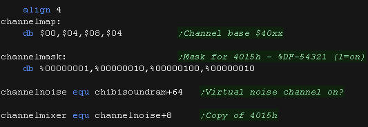
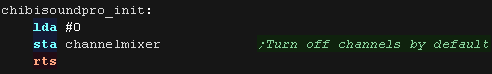
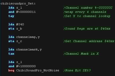
| The channel number could be anything from 0-127, but we'll only
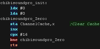
look at the bottom 4 bits, so we'll only work with 4 'channels' We need some lookup tables to work with the channels The first maps the 4 virtual channels to the addresses $4000,$4004 and $4008 The second is a bitmask for the 'sound on' bits of port $4015 We only have one noise channel, but ChibisoundPro want's one for each channel, we therefore track these 'virtual noise channels' with 4 bytes of ram, so we know when to turn the actual noise off. Finally we keep a copy of the enabled mixer channels in $4015 Before we run ChibiSound we run the Init routine 'chibisoundpro_init' which zeros this mixer cache. |
  |
| When we want to set a channel, we first need to set z_bc to point
to the start of the sound registers, we set this pair to $4000/4/8
from the Channelmask lookup, We also load X with the mask for the channel bit in the mixer of $4015 |
 |
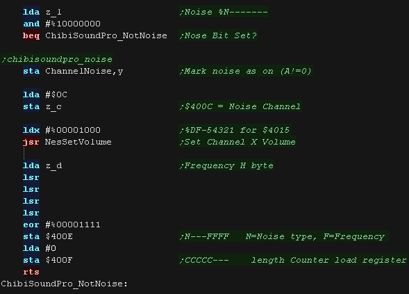
| Next we check if we need to turn on the noise (bit 7 of L) If we need noise on, we set the flag for the 'virtual channel' to something nonzero (so we can simulate 3/4 noise channels) We then need to set the volume of channel 4, and the frequency of $400E and the counter of $400F |
 |
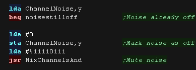
| If we're not using noise, we check the noise flag. If noise was
previously on, then we need to turn it off and clear the flag. |
 |
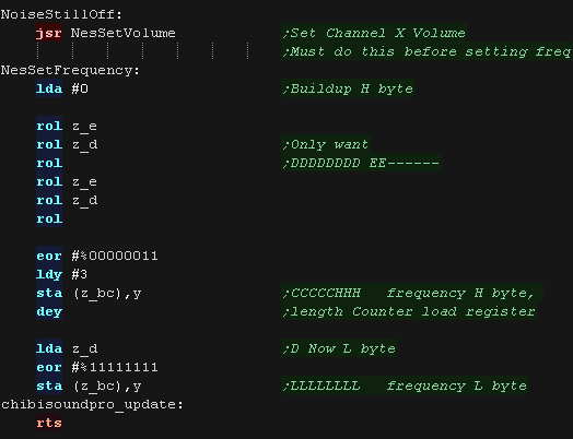
| Now we need to set the tone! First we set the volume for the channel, and turn it on - we need to do this before we set the frequency. We then shift our 16 bits of z_de into 10 bits. and set the frequency of $4003/2 or equivalent |
 |
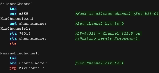
| To silence a channel, we clear it's bit of port $4015 To sound a channel, we set it's bit of port $4015 |
 |
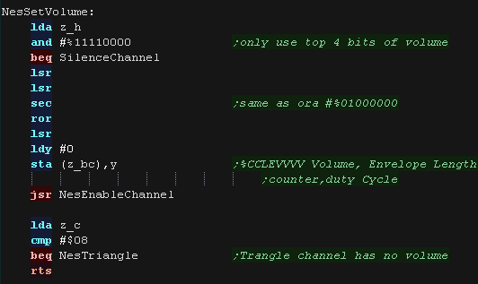
| When we want to set the volume we set the $4000/4 register using
the top 4 bits of H If the volume is zero, we silence the channel. The Triangle channel doesn't actually have a volume, and we need to adjust the frequency, so we have a special routine for that |
 |
| The triangle routine sets the linear counter of the triangle channel, and tweaks the frequency in DE, as the triangle channel is very different in pitch! | 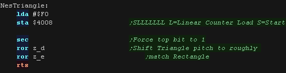 |
| As it's using
the triangle wave, The 3rd channel probably won't sound the same
as the first two. On the CPC, channel 1 is the Center channel, and 2/3 are Left/Right panned. As there's no guarantee how many channels there are, The rule of thumb is that in ChibiTracks, you should use Channel 1 first as your main music, 2 second, and 3 only if 1 and 2 are doing something else. The author of these tutorials always uses channel 1 for the main theme, 2 for accompanying music, and 3 for Drum sounds and other very minor sfx. |
 |

ChibiSound PRO!
ChibiSound is the sound driver that handles the particularities of a system, there is typically one driver per system, though the CPC and MSX drivers are essentially identical except for the AY register setting routines.
The original 'ChibiSound' gave us one channel, one Volume bit, six pitch bits, and the ability to turn noise on. Pitches were not matched across systems, so sound 32 won't sound the same on all systems.
The updated 'ChibiSound Pro' gives us all the channels provided by the hardware, 8 volume bits, 16 pitch bits, and the ability to turn noise on. Pitches were not matched across systems, however the 'ChibiOctave' lookup table provides values which ARE matched across all systems.
ChibiSound PRO is essentially a reduced subset of AY functionality, and was designed on the Z80 - it's 'PRO' suffix is a parody of the 'SoundBlaster PRO' - which could only do 8 bit sound so wasn't up to professional standards! (neither is ChibiSound PRO)
ChibiSound PRO provides a standard interface to the underlying hardware, it allows the following features to be set for each channel on the underlying hardware:
| Function |
Zero page entry |
Notes: |
| Channel Number (bit 0-6) Noise On/Off (bit 7) |
H | Multiple channels can be supported, but on single channel systems
only Channel 0 will be sure to play. If possible Channel 0 will be a center channel, Channels 1+ may be left/right Noise bit turns the noise effect on (1) or off (0) - this can be set on any channel, if the underlying hardware only supports one noise channel, this will be resolved by the driver. |
| Volume | L | Set volume of the channel (0-255). Higher numbers are louder. O is off |
| Pitch | DE | Set the pitch of the channel (0-65535). Higher numbers are higher
pitch. Using DE does not standardize the resulting pitch - however a 'Lookup table' of notes 'ChibiOctave' provides a standardized way of getting the correct DE value to get a pitch correct note on the platform. |
| The
new driver is a big improvement on the old one but doesn't really
deserve the PRO suffix! It's a parody of the early 'Soundblaster Pro' sound cards, which could only do 8 bit digital sound, so weren't really of 'pro spec' either! |
|
The PC Engine Sound Hardware
We have to snd some commands to $0804 to tell the PSG we're going to write data.. then send the data to $0806
We also need to set the volumes correctly.
The PSG is controlled by 10 registers... first a channel should be selected with Register 0... Channels are numbered 0-5 (written 1-6 in the manuals)
| Reg | Address | Meaning | Channels | 7 | 6 | 5 | 4 | 3 | 2 | 1 | 0 | Bit Meaning |
| 0 | $0800 | Channel Select | All | - | - | - | - | - | C | C | C | Channel Select |
| 1 | $0801 | Main Amplitude Level | All | L | L | L | L | R | R | R | R | L/R Volume |
| 2 | $0802 | Frequency L | 0-5 | L | L | L | L | L | L | L | L | |
| 3 | $0803 | Frequency H | 0-5 | - | - | - | - | H | H | H | H | |
| 4 | $0804 | Channel On/Write | 0-5 | E | D | - | V | V | V | V | V | Enable/data addr... reset or DirectDA� Volume |
| 5 | $0805 | LR Volume | 0-5 | L | L | L | L | R | R | R | R | L/R Volume |
| 6 | $0806 | Waveform Data | 0-5 | - | - | - | W | W | W | W | W | Wave data (write 32 times) |
| 7 | $0807 | Noise Enable | 4-5 | E | - | - | N | N | N | N | N | Enable noise� Noise freq |
| 8 | $0808 | LFO Freq | All | F | F | F | F | F | F | F | F | lfo Frequency |
| 9 | $0809 | LFO Control | All | T | - | - | - | - | - | C | C | lfo Trigger� Control |
|
We're going to
use channels 0-3 as tone channels, and channel 4 as for Noise. We'll detect when the driver is told to turn a noise channel on, and 'redirect' it to channel 4. |
The Chibisound Pro driver
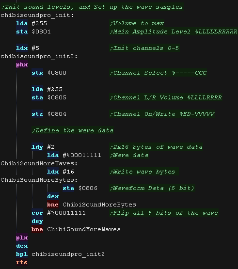
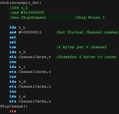
| Before we can use Chibisound we need to set up the channels. We set the main volume level to the maximum with port $0801 Next we set up all the channels using X as a channel number. We select the channel with port $0800 We set each channel's Left/Right volume to max with port $0805, but we set the channel to silent with $0804 We need to define a wave sample or we'll hear no sound - it has 32 5 bit samples, We set half of these to %00011111, and half to %00000000 - effectively a square wave. |
 |
| As we only use channel 4 for noise, We need a few bytes of memory
(4) to keep track of the virtual noise channels We only use the bottom two bits of the channel number (L), so we only work with channels 0-3 |
  |
| if the top bit of L is one, we need to turn on the noise. In this case, we need to flag this channel as having the noise on.... we also need to silence the tone channel, then select channel 4 as the actual recipient of the frequency and volume settings. |
 |
| If the noise is now off, we check what the previous state was. If the noise was on, but is now off, we need to silence channel 4, and turn off the noise |
 |
| We select the channel number with port $0800 We need to set the volume level. We are provided an 8 bit volume in H, we need a 5 bit volume for port $8004 - we also need to set the top 'enable' bit to one. |
 |
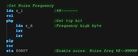
| We set the 5 bit frequency setting for noise with port $0807, but
only enable it if the top bit of L is one. |
 |
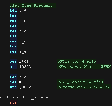
| Finally we set the 12 bit tone pitch, we use port $0802 and $0803
for this. The frequencies are the opposite of what we want, so we flip the bits of the DE pair after shifting them to the correct bit position We've now done everything to set the tone |
 |
| We have a lookup table to define the notes of the octave, we can calculate sharps or flats by taking two tones, and dividing them by two. | 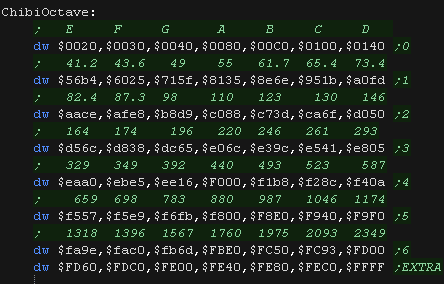 |

ChibiSound PRO!
ChibiSound is the sound driver that handles the particularities of a system, there is typically one driver per system, though the CPC and MSX drivers are essentially identical except for the AY register setting routines.
The original 'ChibiSound' gave us one channel, one Volume bit, six pitch bits, and the ability to turn noise on. Pitches were not matched across systems, so sound 32 won't sound the same on all systems.
The updated 'ChibiSound Pro' gives us all the channels provided by the hardware, 8 volume bits, 16 pitch bits, and the ability to turn noise on. Pitches were not matched across systems, however the 'ChibiOctave' lookup table provides values which ARE matched across all systems.
ChibiSound PRO is essentially a reduced subset of AY functionality, and was designed on the Z80 - it's 'PRO' suffix is a parody of the 'SoundBlaster PRO' - which could only do 8 bit sound so wasn't up to professional standards! (neither is ChibiSound PRO)
ChibiSound PRO provides a standard interface to the underlying hardware, it allows the following features to be set for each channel on the underlying hardware:
| Function |
Zero page entry |
Notes: |
| Channel Number (bit 0-6) Noise On/Off (bit 7) |
H | Multiple channels can be supported, but on single channel systems
only Channel 0 will be sure to play. If possible Channel 0 will be a center channel, Channels 1+ may be left/right Noise bit turns the noise effect on (1) or off (0) - this can be set on any channel, if the underlying hardware only supports one noise channel, this will be resolved by the driver. |
| Volume | L | Set volume of the channel (0-255). Higher numbers are louder. O is off |
| Pitch | DE | Set the pitch of the channel (0-65535). Higher numbers are higher
pitch. Using DE does not standardize the resulting pitch - however a 'Lookup table' of notes 'ChibiOctave' provides a standardized way of getting the correct DE value to get a pitch correct note on the platform. |
| The
new driver is a big improvement on the old one but doesn't really
deserve the PRO suffix! It's a parody of the early 'Soundblaster Pro' sound cards, which could only do 8 bit digital sound, so weren't really of 'pro spec' either! |
|
PET Sound
The PET did not have any built in sound, but a speaker can be connected to the IO port.
The PET is capable of up to 4 octaves... one of 3 possible pairs can be selected with $E84A
Address $E84B will turn the sound on or off... we
write #16 to turn it on, #0 to turn it off.
Address $E84A can be used to select the Octave with
value 15/51/85
Address $E848 can be used to select the note, a
value of 64-255 should be passed.
It is not possible to set the volume, or play multiple tones at the same time.
| Note Freq | octave=15 | octave=51 | octave=85 | |||
| Octave 0 | Octave 1 | Octave 1 | Octave 2 | Octave 2 | Octave 3 | |
| B | 251 | 125 | 251 | 125 | 251 | 125 |
| C | 238 | 118 | 238 | 118 | 238 | 118 |
| C# | 224 | 110 | 224 | 110 | 224 | 110 |
| D | 210 | 104 | 210 | 104 | 210 | 104 |
| D# | 199 | 99 | 199 | 99 | 199 | 99 |
| E | 188 | 93 | 188 | 93 | 188 | 93 |
| F | 177 | 88 | 177 | 88 | 177 | 88 |
| F# | 168 | 83 | 168 | 83 | 168 | 83 |
| G | 158 | 78 | 158 | 78 | 158 | 78 |
| G# | 149 | 74 | 149 | 74 | 149 | 74 |
| A | 140 | 69 | 140 | 69 | 140 | 69 |
| A# | 133 | 65 | 133 | 65 | 133 | 65 |
|
The Pet can't
really do noise... or volume... or multiple channels... or a wide
range of octaves (only 4!)... Uh... well, we'll do the best we can! |
The Chibisound Pro driver
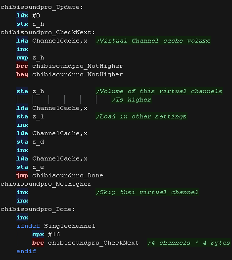
| Our music software wants at least 3 channels, but we only have
1... what to do?? One option would be to ignore all but channel 1.... The other is to remember what all 3 channels want to play, then play the loudest one... That's what we'll do! Here we take the request, and store it's settings in a 'virtual channel' for later (4 in total). |
  |
| The 'Update' Procedure will step through the 4 virtual channels,
find the loudest and load it's settings into the 4 zero page
entries. |
 |
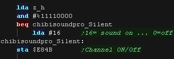
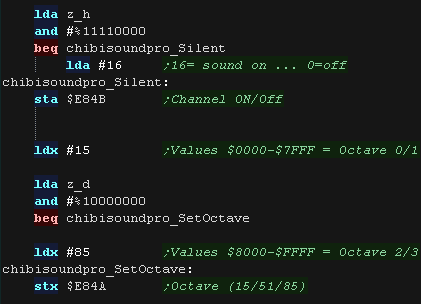
| First we need to turn sound ON or OFF with port $E84B We can't do volume levels, so if our volume is <15 we'll treat it as off and write 0, otherwise we'll turn it on by writing 16 |
 |
| We need to set the octave, we do this with port $E84A. We look at the top bit of our DE pair, if it's 0 we'll use Octave 0/1 by writing #15 ... if it's 1 we'll use Octave 2/3 by writing #85 |
 |
| We need to write a tone value to $E848, the value should be in the
range 64-255 To achive this we take the bottom 7 bits of D, add 64, and add half of D. We write this value to port $E848... and we're done! |
|
| We have a lookup table to define the notes of the octave, we can calculate sharps or flats by taking two tones, and dividing them by two. | 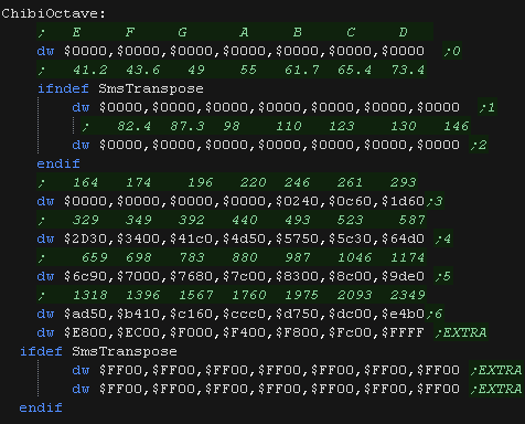 |

ChibiSound PRO!
ChibiSound is the sound driver that handles the particularities of a system, there is typically one driver per system, though the CPC and MSX drivers are essentially identical except for the AY register setting routines.
The original 'ChibiSound' gave us one channel, one Volume bit, six pitch bits, and the ability to turn noise on. Pitches were not matched across systems, so sound 32 won't sound the same on all systems.
The updated 'ChibiSound Pro' gives us all the channels provided by the hardware, 8 volume bits, 16 pitch bits, and the ability to turn noise on. Pitches were not matched across systems, however the 'ChibiOctave' lookup table provides values which ARE matched across all systems.
ChibiSound PRO is essentially a reduced subset of AY functionality, and was designed on the Z80 - it's 'PRO' suffix is a parody of the 'SoundBlaster PRO' - which could only do 8 bit sound so wasn't up to professional standards! (neither is ChibiSound PRO)
ChibiSound PRO provides a standard interface to the underlying hardware, it allows the following features to be set for each channel on the underlying hardware:
| Function |
Zero page entry |
Notes: |
| Channel Number (bit 0-6) Noise On/Off (bit 7) |
H | Multiple channels can be supported, but on single channel systems
only Channel 0 will be sure to play. If possible Channel 0 will be a center channel, Channels 1+ may be left/right Noise bit turns the noise effect on (1) or off (0) - this can be set on any channel, if the underlying hardware only supports one noise channel, this will be resolved by the driver. |
| Volume | L | Set volume of the channel (0-255). Higher numbers are louder. O is off |
| Pitch | DE | Set the pitch of the channel (0-65535). Higher numbers are higher
pitch. Using DE does not standardize the resulting pitch - however a 'Lookup table' of notes 'ChibiOctave' provides a standardized way of getting the correct DE value to get a pitch correct note on the platform. |
| The
new driver is a big improvement on the old one but doesn't really
deserve the PRO suffix! It's a parody of the early 'Soundblaster Pro' sound cards, which could only do 8 bit digital sound, so weren't really of 'pro spec' either! |
|
VIC Sound
There are 3 sound channels for the 3 different frequencies, one for
random noise, and a volume setting...
As well as volume The top 4 bits of the $900E also handles color
| Address | Meaning | Bits | Details |
| $900A | Frequency for oscillator 1 (Bass) | OFFFFFFF | O=On F=Frequency |
| $900B | Frequency for oscillator 2 (medium) | OFFFFFFF | O=On F=Frequency |
| $900C | Frequency for oscillator 3 (high freq) | OFFFFFFF | O=On F=Frequency |
| $900D | Frequency of noise source | OFFFFFFF | O=On F=Frequency |
| $900E | Volume of all sound / Auxiliary color information | CCCCVVVV | V=Volume C=Aux color |
|
We'll need to
use all 3 oscillators to get the widest range of tones possible,
but while octave $900B has a partial overlap with the octaves of
$900A/C, we won't try to use it to play a second tone, as this
would be hard to do consistently, so we'll only play one tone at a
time. |
The Chibisound Pro driver
| Our music software wants at least 3 channels, but we only have
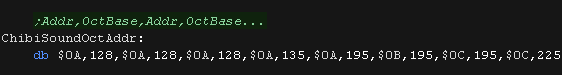
1... what to do?? One option would be to ignore all but channel 1.... The other is to remember what all 3 channels want to play, then play the loudest one... That's what we'll do! We also need an octave lookup, with the bottom byte of the sound register addresses ($900A/B/C) We need to clear the cache before we start |
  |
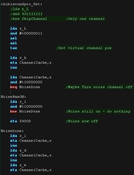
| Here we take the request, and store it's settings in a 'virtual
channel' for later (4 in total). If the noise is now off, we need to check if it was on before... if it was we'll silence the nosie now. |
 |
| The 'Update' Procedure will step through the 4 virtual channels,
find the loudest and load it's settings into the 4 zero page
entries. |
|
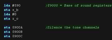
| We set BC to $9000... we'll use Y to specify an offset to specify
the actual channel we want to use. First, We silence all the channels |
 |
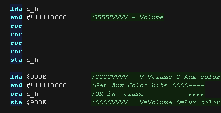
| We need to set the volume, we do this with $900E It only takes a 4 bit volume level |
 |
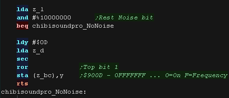
| If the noise is on, we need to set the 7 bit frequency with port
$900D Once we have, we're done! |
 |
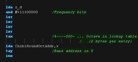
| We use the top 3 pitch bits to calculate an address in the lookup
table. Each entry has two bytes |
 |
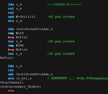
| We need to convert the remaining pitch bits for the selected
octave. As the octave goes up, we need to halve the frequency to get an 'equal' tone. We send this to the port number of the chosen octave. |
 |
| We have a lookup table to define the notes of the octave, we can calculate sharps or flats by taking two tones, and dividing them by two. | 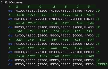 |
| View Options |
| Default Dark |
| Simple (Hide this menu) |
| Print Mode (white background) |
| Top Menu |
| ***Main Menu*** |
| Youtube channel |
| Patreon |
| Introduction to Assembly (Basics for absolute beginners) |
| Amazon Affiliate Link |
| AkuSprite Editor |
| ChibiTracker |
| Dec/Bin/Hex/Oct/Ascii Table |
| Alt Tech |
| Archive.org |
| Bitchute |
| Odysee |
| Rumble |
| DailyMotion |
| Please note: I wlll upload more content to these alt platforms based on the views they bring in |
| 68000 Content |
| ***68000 Tutorial List*** |
Learn 68000 Assembly  |
| Hello World Series |
| Platform Specific Series |
| Simple Samples |
| Grime 68000 |
| 68000 Downloads |
| 68000 Cheatsheet |
| Sources.7z |
| DevTools kit |
| 68000 Platforms |
| Amiga 500 |
| Atari ST |
| Neo Geo |
| Sega Genesis / Mega Drive |
| Sinclair QL |
| X68000 (Sharp x68k) |
| 8086 Content |
| Learn 8086 Assembly |
| Platform Specific Series |
| Hello World Series |
| Simple Samples |
| 8086 Downloads |
| 8086 Cheatsheet |
| Sources.7z |
| DevTools kit |
| 8086 Platforms |
| Wonderswan |
| MsDos |
| ARM Content |
| Learn ARM Assembly |
| Learn ARM Thumb Assembly |
| Platform Specific Series |
| Hello World |
| Simple Samples |
| ARM Downloads |
| ARM Cheatsheet |
| Sources.7z |
| DevTools kit |
| ARM Platforms |
| Gameboy Advance |
| Nintendo DS |
| Risc Os |
| Risc-V Content |
| Learn Risc-V Assembly |
| Risc-V Downloads |
| Risc-V Cheatsheet |
| Sources.7z |
| DevTools kit |
| MIPS Content |
| Learn Risc-V Assembly |
| Platform Specific Series |
| Hello World |
| Simple Samples |
| MIPS Downloads |
| MIPS Cheatsheet |
| Sources.7z |
| DevTools kit |
| MIPS Platforms |
| Playstation |
| N64 |
| PDP-11 Content |
| Learn PDP-11 Assembly |
| Platform Specific Series |
| Simple Samples |
| PDP-11 Downloads |
| PDP-11 Cheatsheet |
| Sources.7z |
| DevTools kit |
| PDP-11 Platforms |
| PDP-11 |
| UKNC |
| TMS9900 Content |
| Learn TMS9900 Assembly |
| Platform Specific Series |
| Hello World |
| TMS9900 Downloads |
| TMS9900 Cheatsheet |
| Sources.7z |
| DevTools kit |
| TMS9900 Platforms |
| Ti 99 |
| 6809 Content |
| Learn 6809 Assembly |
| Learn 6309 Assembly |
| Platform Specific Series |
| Hello World Series |
| Simple Samples |
| 6809 Downloads |
| 6809/6309 Cheatsheet |
| Sources.7z |
| DevTools kit |
| 6809 Platforms |
| Dragon 32/Tandy Coco |
| Fujitsu FM7 |
| TRS-80 Coco 3 |
| Vectrex |
| 65816 Content |
| Learn 65816 Assembly |
| Hello World |
| Simple Samples |
| 65816 Downloads |
| 65816 Cheatsheet |
| Sources.7z |
| DevTools kit |
| 65816 Platforms |
| SNES |
| eZ80 Content |
| Learn eZ80 Assembly |
| Platform Specific Series |
| eZ80 Downloads |
| eZ80 Cheatsheet |
| Sources.7z |
| DevTools kit |
| eZ80 Platforms |
| Ti84 PCE |
| IBM370 Content |
| Learn IBM370 Assembly |
| Simple Samples |
| IBM370 Downloads |
| IBM370 Cheatsheet |
| Sources.7z |
| DevTools kit |
| Super-H Content |
| Learn SH2 Assembly |
| Hello World Series |
| Simple Samples |
| SH2 Downloads |
| SH2 Cheatsheet |
| Sources.7z |
| DevTools kit |
| SH2 Platforms |
| 32x |
| Saturn |
| PowerPC Content |
| Learn PowerPC Assembly |
| Hello World Series |
| Simple Samples |
| PowerPC Downloads |
| PowerPC Cheatsheet |
| Sources.7z |
| DevTools kit |
| PowerPC Platforms |
| Gamecube |
| Work in Progress |
| ChibiAndroids |
| Misc bits |
| Ruby programming |
Buy my Assembly programming book
on Amazon in Print or Kindle!


Available worldwide!
Search 'ChibiAkumas' on
your local Amazon website!
Click here for more info!


Buy my Assembly programming book
on Amazon in Print or Kindle!
Available worldwide!
Search 'ChibiAkumas' on
your local Amazon website!
Click here for more info!
Buy my Assembly programming book
on Amazon in Print or Kindle!
Available worldwide!
Search 'ChibiAkumas' on
your local Amazon website!
Click here for more info!
Buy my Assembly programming book
on Amazon in Print or Kindle!
Available worldwide!
Search 'ChibiAkumas' on
your local Amazon website!
Click here for more info!
Buy my Assembly programming book
on Amazon in Print or Kindle!
Available worldwide!
Search 'ChibiAkumas' on
your local Amazon website!
Click here for more info!
Buy my Assembly programming book
on Amazon in Print or Kindle!
Available worldwide!
Search 'ChibiAkumas' on
your local Amazon website!
Click here for more info!
Buy my Assembly programming book
on Amazon in Print or Kindle!
Available worldwide!
Search 'ChibiAkumas' on
your local Amazon website!
Click here for more info!
Buy my Assembly programming book
on Amazon in Print or Kindle!
Available worldwide!
Search 'ChibiAkumas' on
your local Amazon website!
Click here for more info!
Buy my Assembly programming book
on Amazon in Print or Kindle!
Available worldwide!
Search 'ChibiAkumas' on
your local Amazon website!
Click here for more info!
Buy my Assembly programming book
on Amazon in Print or Kindle!
Available worldwide!
Search 'ChibiAkumas' on
your local Amazon website!
Click here for more info!
Buy my Assembly programming book
on Amazon in Print or Kindle!
Available worldwide!
Search 'ChibiAkumas' on
your local Amazon website!
Click here for more info!