

Learn Multi platform 6502 Assembly Programming... For Monsters!
Platform Specific Lessons


| Compared to other
systems, the 'Hardware Sprites' of the atari are pretty limited,
and may not be very useful as they are just 8 pixels wide and one
color That said, they may be useful in some cases, you could combine them together to make a 32x32 player sprite - or use them for parallax effects or something! |
 |
Atari 800 / 5200
Sprites
The Atari's hardware sprites are very weird!
Basically each sprite is 8 pixels wide and just 2 colors
(1+transparent)... there are 4 'normal' ones that are 8 pixels wide....
and 4 missile sprites that are just 2(!) pixels wide... but we can
position them together to give us 5 sprites.
Despite being 8 pixels wide... each sprite is up to 128 pixels tall
(or 256 in hires mode) - the entire height of the screen!... if you can't
guess this is because the systems is changing the data each rasterline.
The data used to draw the sprite is taken from a single pointer at $D407... if this
pointer is set to $18 then all the sprites will use the $1800-$1FFF range
- the exact address differs depending on whether the Resolution bit of
$D400 is set to 0 or 1... in Res1 Sprites will be at $1800+$400 - $1C00
... or in Res0 $1800+$200 = $1A00
On an Atari 800 where the GTIA is at $D000 this would give the following
addresses for the sprite settings GTIA is at $C000 on the 5200)
| Player | Res0 Data | Res1Data | Width | Color | Xpos |
| 0 | $1A00+ypos | $1C00+ypos | $D008 | $D012 | $D000 |
| 1 | $1A80+ypos | $1D00+ypos | $D009 | $D013 | $D001 |
| 2 | $1B00+ypos | $1E00+ypos | $D00A | $D014 | $D002 |
| 3 | $1B80+ypos | $1F00+ypos | $D00B | $D015 | $D003 |
| 4 (Missiles) | $1980 | $1B00 | $D00C | $D019* / $D012-$D015 |
$D004-$D007 |
The Sprites can be in front of, or behind the background... register $D01B (PRIOR) controls the order... and allows all 4 missiles to use color defined at $D019 as the sprite color - instead of the 4 player colors!
Note PRIOR is at $D01B... it seems to be incorrectly reported as $D10B or $D21B in some documentation!!!
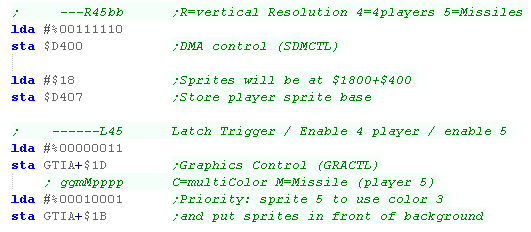
| To make use of sprites, we need to
set the addresses shown above for the player sprite attributes, we
also need to turn sprites on! The example code to the right should do the job! note you needto set symbol GTIA to $D000 on the Atari 800, or $C000 on the Atari 5200 |
lda
#%00111110 sta $D400 ;DMA control (SDMCTL) lda #$18 ;Sprites will be at $1800+$300 (or +$180 in low res mode) sta $D407 ;Store player sprite base lda #%00000011 sta GTIA+$001D ;Graphics Control (GRACTL) lda #%00010001 ;Priority: sprite 5 to use color 3 sta GTIA+$1B ;and put sprites in front of background |
Atari 800 / 5200
Sprite Registers
| Group | Name | Description | Address A80 | Address A52 | Bits | Notes |
| GTIA | HPOSP0 | horizontal position of player 0 | $D000 | $C000 | ||
| GTIA | HPOSP1 | horizontal position of player 1 | $D001 | $C001 | ||
| GTIA | HPOSP2 | horizontal position of player 2 | $D002 | $C002 | ||
| GTIA | HPOSP3 | horizontal position of player 3 | $D003 | $C003 | ||
| GTIA | HPOSM0 | horizontal position of missile 0 (Player 4) | $D004 | $C004 | ||
| GTIA | HPOSM1 | horizontal position of missile 1 (Player 4) | $D005 | $C005 | ||
| GTIA | HPOSM2 | horizontal position of missile 2 (Player 4) | $D006 | $C006 | ||
| GTIA | HOPSM3 | horizontal position of missile 3 (Player 4) | $D007 | $C007 | ||
| GTIA | SIZEP0 | player 0 size | $D008 | $C008 | ------WW | Width of sprite (0-3) |
| GTIA | SIZEP1 | player 1 size | $D009 | $C009 | ------WW | Width of sprite (0-3) |
| GTIA | SIZEP2 | player 2 size | $D00A | $C00A | ------WW | Width of sprite (0-3) |
| GTIA | SIZEP3 | player 3 size | $D00B | $C00B | ------WW | Width of sprite (0-3) |
| GTIA | SIZEM | missile size | $D00C | $C00C | wwWWwwWW | Width of sprite (Need to set all 4 parts) |
| GTIA | GRAFP0 | player 0 graphics | $D00D | $C00D | (Used by DMA) | |
| GTIA | GRAFP1 | player 1 graphics | $D00E | $C00E | (Used by DMA) | |
| GTIA | GRAFP2 | player 2 graphics | $D00F | $C00F | (Used by DMA) | |
| GTIA | GRAFP3 | player 3 graphics | $D010 | $C010 | (Used by DMA) | |
| GTIA | GRAFM | missile graphics | $D011 | $C011 | (Used by DMA) | |
| GTIA | COLPM0 | color/brightness, player/missile 0 | $D012 | $C012 | ||
| GTIA | COLPM1 | color/brightness, player/missile 1 | $D013 | $C013 | ||
| GTIA | COLPM2 | color/brightness, player/missile 2 | $D014 | $C014 | ||
| GTIA | COLPM3 | color/brightness, player/missile 3 | $D015 | $C015 | ||
| GTIA | COLPF3 | color/brightness of setcolor 3 / Player 5 (missile) | $D019 | $C019 | ||
| GTIA | PRIOR | p/m priority and GTIA mode | $D01B | $C01B | GGmMpppp | G=gtia mode (0=normal) C=multiColor M=Missile (player 5) pppp=priority setting (1=sprites in front 4=behind) |
| GTIA | GRACTL | graphics control | $D01D | $C01D | ------L45 | Latch Trigger / Enable 4 player / enable 5 (missiles) |
| ANTIC | DMACTL | Direct Memory access control (DMA) | $D400 | $C400 | ||
| ANTIC | PMBASE | player/missile address / 256 | $D407 | $C407 |
Coding a Player sprite
(sprite 0-3)
| The procedure for setting Player sprites 0-4 are all basically the
same, we need a 1 byte wide sprite (1 bit per pixel) file, and to
set our 'Y position' we'll need to load it into the correct memory
address. First of all we need to set up the sprite settings, we need to turn on sprites, set them to appear in front of the background, and set the memory address of our sprites - we're using 'High Resolution mode, and our sprite base is at $1800... so Player 0's sprite data starts at $1C00 We need to enable the DMA - this is what copies the sprite data to the screen register each screen line to change the sprite vertically. We're also enabling 'Player 4' - this combines the missile sprites into one 'fifth' sprite - we'll learn how to use it in a moment! |
 |
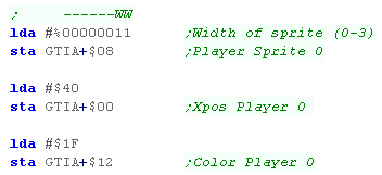
| OK, we're ready to define our sprite! First we set the Xscale with $D008 - but because the GTIA is in a different place on the Atari 5200 - we'll refer to it with GTIA+$08 ... the setting can be 0-3... there is no Yscale - we need to alter our bitmap data to make the sprite taller! Next We'll set the Xpos with $D000... There is no Ypos - the sprite covers the entire height of the screen - we need to alter the bitmap data according to where we want it to be. Finally We set a color with $D012 |
 |
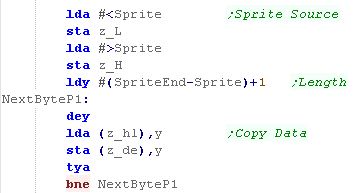
| We need to set the sprite data, we do a memory copy from the
'Sprite' label in our code, and write to the $1C00 - adding an
offset to change the Ypos ($80 in this case) The same procedure can be used for sprite 1-3 - just change the memory addresses used. |
 |
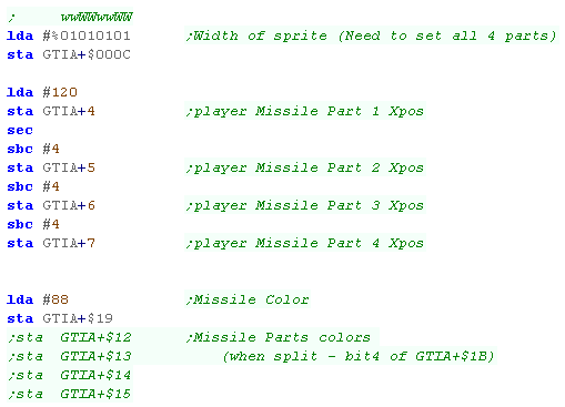
Coding the Missile sprite (sprite 4)
| The 4th 'Player' sprite is made up of the 4x two pixel missiles... Because of this, we need to set the width in 4 different bit pairs... We also need to align the Xpos of all 4 parts to make the single sprite. Depending on our color settings, we can set each part separately, but it's more simple to set them with a shared color, and set them together - we do this with bit 4 of GTIA+$1B |
 |
| We need to load the sprite data into the the ram for Sprite 4 (Missile) At $1B00 - again we need to add the Ypos offset. ($40 in this case) | 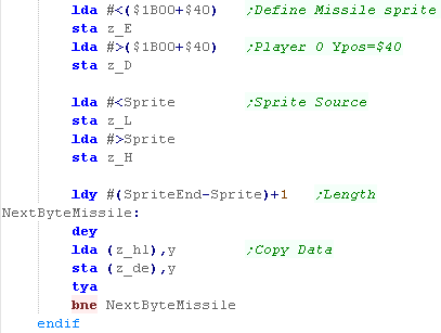 |
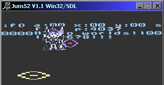
| In this example we've used the two sprites to draw 'targets'
onscreen... The Player 0 sprite (Yellow) has been scaled super wide! |
 |
 |
The weird hardware of the
Atari probably goes back to the early days of pong!... the 4 player
sprites would be the characters - and the 4 two pixel missiles
would be the balls or bullets for those players. Unfortunately it's not really very impressive by even the standards of the 80s! |

Hardware Sprites
Unlike other systems, Lynx hardware sprites are not an extra layer! the
'Suzy' graphics chip draws the sprite into the Vram area of the 6502's
addressable range
This may leave you wondering why not just do our sprites in software with
the 6502... but the Suzy chip is VERY fast... it's a 16mhz 16 bit chip...
and can even do dynamic scaling of sprites!
Sprites for the Suzy chip have to be held in RAM, and need a 'Sprite
control block' to define the drawing of a sprite... this pointer is passed
to the Suzy chip to get it to draw a sprite
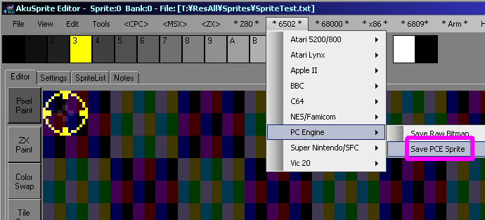
My Akusprite Editor can Export Literal and RLE bitmaps...
but lets take a look at the theory
| Sprites can be 'Literal' (plain bmp) or 'RLE compressed' (defined
by bit 7 of byte two of the SCB - SCBCTL1).... the colordepth is
defined in SPRCTL0 (See later) Each line of a sprite starts with a byte - this an offset to the next line... effectively the number of bytes in the line +1 .... effectively the pointer to the next line. 1 or 0 in this position have special meanings!... 0 means the end of the sprite... 1 means the end of the 'quardrent'... note this is optional! Akusprite does not use it! Quadrent rendering is where the sprite is drawn in 4 sections from the middle... with a 1 byte marking each 1/4 of the sprite... (followed by another 'offset to next line' byte) the first quadrent is DownRight (default)... the second quadrent is UpRight the third quadrent is UpLeft)... the fourth quadrent is DownLeft Apparently there is a bug in the hardware - the last bit of each line must be 0! - we should always have a 0 at the end of our sprites to counter it - color 0 is transparent anyway! You can see a Literal Sprite to the right... the Literal bitmap data is in green, and the header bytes are in cyan |
Literal
Sprite Example (BMP) LynxSprite: db $8, $11, $11, $11, $11, $11, $10,0 db $8, $10, $0, $0, $0, $0, $10,0 db $8, $10, $04, $44, $44, $0, $10,0 db $8, $10, $04, $3, $04, $0, $10,0 db $8, $10, $04, $3, $04, $0, $10,0 db $8, $10, $04, $44, $44, $0, $10,0 db $8, $10, $0, $0, $0, $0, $10,0 db $8, $11, $11, $11, $11, $11, $10,0 db 0 |
| RLE Sprite
Data is a bit more tricky.... The first byte in a line is again an offset to the next line as before The next BIT will be a 'block definition'... defining what the following data is... 1 marks that the next data will be LITERAL 0 marks that the next data will be RLE The next 4 bits will be the number of pixels to draw-1... so 0 means 1 pixel, and 15 means 16 pixels... we will call this N If the block is RLE the next 1/2/3/4 bits (depending on bitdepth) will be used for the color to fill the next N pixels If the block LITERAL the next N *(1/2/3/4) bits (depending on bitdepth) will be used for the color of the next N pixels the next bit will be the next 'block definition'... this pattern repeats until the line is done. |
4bpp
RLE Sprite Example db $8 (offset to next line) db %01111000,%00000000 (RLE block...16 pixels... Color 0,0,0,0,0,0,0,0,0,0,0,0,0,0,0,0) db %00001001,%10000000 (RLE block...2 pixles... Color 3,3) db %10010000,%10010001,%10000000 (Literal block...3 pixels... Color 1,2,3) (next line starts here) |
| Don't worry
about all the work of creating bitmap data, just use AkuSprite
Editor (or similar) to export valid bitmaps for the Lynx... It's worth knowing the theory, but it's unlikely you'd really want to do things yourself. |
 |
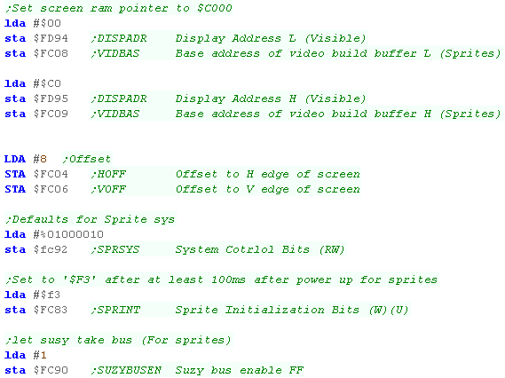
The Source code
| efore we can use sprites, we need to set up the screen hardware,
defining the Ram area the sprites will be drawn to (in this case the
same as the visible screen)... We also need to set any offset for sprite clipping - we're setting the first visible pixel at (8,8) We also need to send some bytes to the sprite hardware to initialize it - these are pretty fixed bytes and don't really need changing |
 |
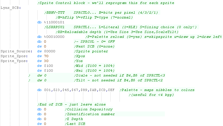
| Our next stage is going to involve setting up a 'Sprite Control
Block' (SCB)... we've got a template we're going to patch our
settings into. The first byte defines the sprite type, in this example we're using a 16 color (4bpp) RLE sprite Note: Our example won't use scaling, but you can do if you want, just change the WID and HEI bytes - $200 would make the sprite 2x larger |
 |
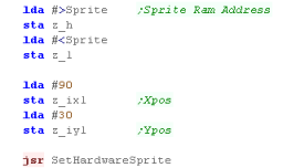
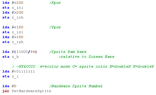
| We're going to define a function called 'SetHardwareSprite'... This will use zeropage entries z_hl to point to the sprite bitmap data. z_ixl is the X position and z_iyl is the Y position of the sprite The function handles the job of setting up the SCB, and calling the Suzy chip to draw the sprite to screen. |
 |
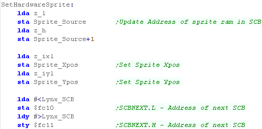
| We need to load the address of the sprite into the SCB We also set the X and Y position of the sprite We also Initialize the start address of the SCB to $FC10/1 We're now ready to get Suzy to draw the sprite. |
 |
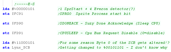
| We're ready to draw the sprite, we need to tell the Suzy chip to
draw the sprite, and the allow Suzy to take over the ram bus... We put the CPU to sleep with $FD91 while the sprite is drawing. For *SOME REASON* the first byte of the SCB is getting altered in the process - I don't know why! |
 |
| In this example we've drawn the Cross-hair sprite to two positions onscreen. | 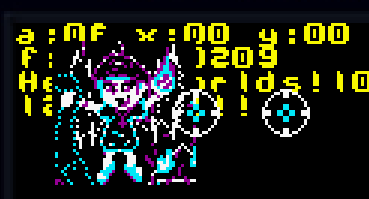 |
 |
Usually
hardware sprites are always onscreen even if the screen/tilemap is
cleared... but the Lynx is different. We'll need to draw all the sprites again for the next frame - which is a pain, but unlike other systems, there is no limit to the number of sprites we have onscreen! |

SATB sprite table
The Sprite table allows for up to 64 sprites... each one has 4 words of data - making 256 words in total... it's held in VRAM between $7F00 and $7FFF
| Vram From | Vram To | Purpose |
| $0000 | $03FF | Min Tilemap (Tiles 0-63) |
| $0400 | $0FFF | Possible Tilemap (Tiles 64-255) |
| $1000 | $7FFF | Tiles 256-2048 |
| $7F00 | $7FFF | SATB sprite table |
| $8000 | $FFFF | PC-Engine only has 64k, so this is unused |
The Sprite table allows for up to 64 sprites... each one has 4 words of data - making 256 words in total... the format is as follows
| Word | F | E | D | C | B | A | 9 | 8 | 7 | 6 | 5 | 4 | 3 | 2 | 1 | 0 | Notes | |
| 1 | - | - | - | - | - | - | Y | Y | Y | Y | Y | Y | Y | Y | Y | Y | Y=Ypos (64 is first visible line) | |
| 2 | - | - | - | - | - | - | X | X | X | X | X | X | X | X | X | X | X=Xpos (32 is first visible line) | |
| 3 | - | - | - | - | - | A | A | A | A | A | A | A | A | A | A | A | A=Address (Top 10 bits $trueaddress>>5 ) | |
| 4 | YF | - | YS | YS | XF | - | - | XS | F | - | - | - | P | P | P | P | YF=Yflip XF=Xflip YS=Ysize XS=Xsize
F=Foreground (infront of tilemap) P=Palette |
Sprite Definitions
The basic sprite size is 16x16, though larger sprites can be created by tilling them, for up to 32x64.... only neighboring sprites can be tilled.Sprites are NOT in the same format as the tilemap, they are 16x16 with 4 bitplanes, but each plane is sent separately
eg - lets look at a sprite, where all pixels are color 0 or color 15
| First
16 bytes (Bitplane 1) |
1110000000000111 1000000100000001 1000000100000001 0000000100000000 0000000100000000 0000000100000000 0000000100000000 0000000111111100 0011111110000000 0000000010000000 0000000010000000 0000000010000000 0000000010000000 1000000010000001 1000000010000001 1110000000000111 |
Second
16 bytes (Bitplane 2) |
2220000000000222 2000000200000002 2000000200000002 0000000200000000 0000000200000000 0000000200000000 0000000200000000 0000000222222200 0022222220000000 0000000020000000 0000000020000000 0000000020000000 0000000020000000 2000000020000002 2000000020000002 2220000000000222 |
Third
16 bytes (Bitplane 3) |
3330000000000333 3000000300000003 3000000300000003 0000000300000000 0000000300000000 0000000300000000 0000000300000000 0000000333333300 0033333330000000 0000000030000000 0000000030000000 0000000030000000 0000000030000000 3000000030000003 3000000030000003 3330000000000333 |
Fourth
16 bytes (Bitplane 4) |
4440000000000444 4000000400000004 4000000400000004 0000000400000000 0000000400000000 0000000400000000 0000000400000000 0000000444444400 0044444440000000 0000000040000000 0000000040000000 0000000040000000 0000000040000000 4000000040000004 4000000040000004 4440000000000444 |
| You don't need to worry about working out the sprite data for the
PC-Engine format, you can export valid 16x16 sprites using my free
Open Source AkuSprite Editor! It's included in the sources.7z file! |
 |
To start the copy we just write the address to Control Register $13
Graphics Registers
| Reg | Name | Meaning |
| $00 | MAWR | Memory Address Write |
| $01 | MARR | Memory Address Read |
| $02 | VRR/VWR | Vram Data Write / Vram Data Read |
| $13 | SATB | VRAM-SATB Block Transfer Source |
Coding for sprites
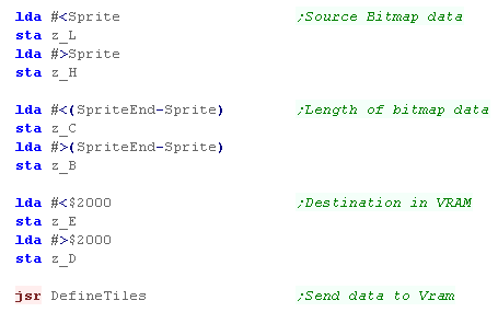
| Transfering Sprite Data Transfering Data to VRAM is the same as with tiles, we specify a source in ram, destination in VRAM, and use DefineTiles to transfer the data to the VRAM See this tutorial for details of how DefineTiles works |
 |
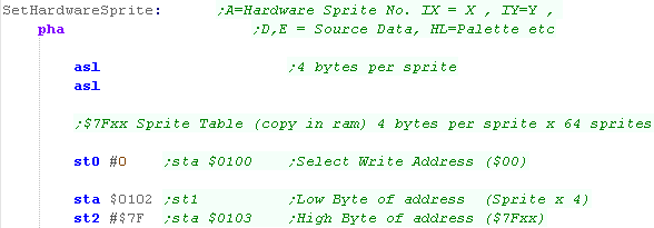
| We're going to create a function called 'SetHardwareSprite' to do
the heavy lifting for us... We'll use zero page entries to define the settings for our sprite A is the hardware sprite number z_IXH/L will define the X position z_IYH/L will define the Y position z_H will set the size & flipping options z_L will select the layer and palette z_DE is the top 11 bits of the address of the sprite data in VRAM (Bits XXXXXXXX XXX-----) - we get them by bitshifting the address with >>5 |
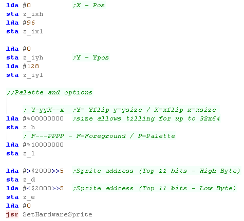 |
| Setting a hardware sprite We're going to need to use the memory mapped hardware graphics ports at $0100/2/3 - and the equivalent ST0/1/2 commands when we're writing fixed values First the function needs to select the VRAM address of the sprite settings - to do this we multiply the sprite number by 4, and select the address (Starting at $7Fxx) by writing to Register $00 (with ST0) |
 |
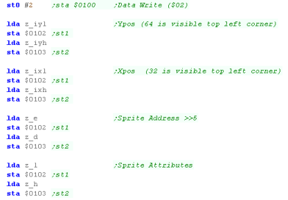
| We need to select Register $02 (with ST0) as we now want to write
bytes to the $7Fxx range we selected before... We write our Ypos, Xpos, Sprite address and Attributes to vram - as the address autoincs, we don't need to do anything else! |
 |
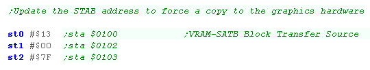
| OK, the data is in VRAM, but that's not enough to change the
visible sprites, we need to initiate a copy of the VRAM to the STAB
sprite table... We do this by writing the VRAM address of our sprites ($7F00) to reg $13 |
 |
| The sprites will now be visible on screen! | 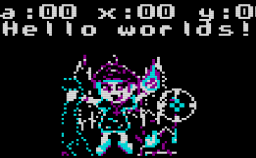 |
 |
In this example we've only looked at a 16x16
sprite, but the PC engine can combine tiles to make sprites up to
32x64, we just need to set more patterns and set the bits to make
the sprite bigger. |
Sprites

Sprites
on the nes are defined by 256 bytes of OAM memory- 4 bytes per sprite
The byte is selected by setting the OAM-address with memory location $2003
- effectively with 4x the sprite number... then by writing the 4
bytes to $2004 (the OAM address autoincs)
| Byte | Purpose | Bits | Meaning |
| 1 | Ypos | YYYYYYYY |
|
| 2 | Tilenum | TTTTTTTT |
|
| 3 | Attribs | VHB---PP | Vflip Hflip Background priority Palette |
| 4 | Xpos | XXXXXXXX |
PPU Graphics ports
To directly alter the sprites, we'll use use ports $2003 and $2004...
$2003 selects the OAM address... then we write the 4 bytes to $2004...
this can only be done during VBLANK - so it's better to use a buffer, and
transfer it to VRAM during Vblank.
| Port | Name | Bits | Details | Notes |
| $2003 | OAMADDR | Sprite address | (0-255) | |
| $2004 | OAMDATA | Sprite data (to write to addr, autoincs) |
Pattern Definitions for sprites and tiles
The NES has 2 pattern tables, they are selected with PPU Register $2000 Bit 4 & 3Basic NES roms have pattern definitions in ROM (CHR-ROM), but we can use a mapper with extra video ram to make things easier - in these tutorials we'll use Mapper 2 - so we don't have to worry about CHR-ROM and can change the patterns whenever we like!
The Famicom uses bitplanes for it's data - 2 bitplanes for 4 colors... this means a tile uses 16 bytes
First we send all 8 lines of the first bitplane, Next we send all 8 lines of the second bitplane.
| Byte Data | Byte Data | ||
| First 8 bytes | 00111100 01111111 01100011 01100011 01111111 01100011 01100011 00000000 |
Second
8 bytes |
00222200 02222222 02200022 02200022 02222222 02200022 02200022 00000000 |
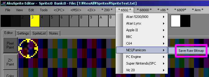
| If you want to create NES sprites, my AkuSprite editor can export
valid format data. It's included in the Sources.7z - and is free and open source. |
 |
| We can set up
sprites in two ways, directly by writing to the OAM, or by making
a buffer, and using the DMA to copy it... The DMA way is better... but first we'll look at the 'simpler' direct way. |
|
Simple Sprite Example
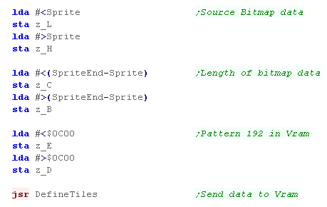
| Sprite data in VRAM is the same as tile data, so we can just use
our DefineTiles function to transfer it. We covered DefineTiles in a previous lesson... |
 |
||||||||||||||||||||||||||||||
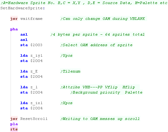
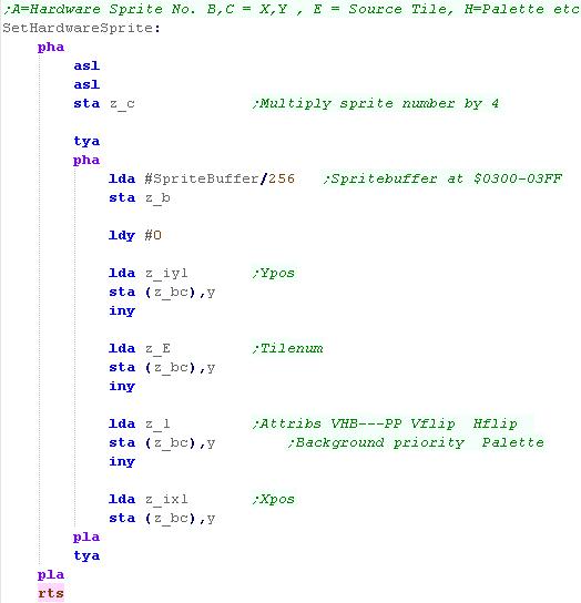
| We're going to create a function called 'SetHardwareSprite' to do
the job of talking to the hardware. A is the hardware sprite number z_IXL will define the X position z_IYL will define the Y position z_L will select the flipping option and palette z_E is the tile number First we need to wait for VBLANK - we use the WaitFrame function we wrote before for this... Then we multiply A by 4 - as there are 4 bytes per sprite... we write A into $2003 - selecting the address in the OAM for the sprite we'll change... We write all 4 bytes to $2004 - it automatically increments the destination address in the OAM, so these 4 writes set the sprite data... Writing to the OAM messes up the scroll position, so we have to reset it with our ResetScroll function |
 |
||||||||||||||||||||||||||||||
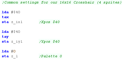
| We're going to show a 16x16 sprite... but sprites on the NES are
8x8 - so we're going to need 4 of them to show our image The top corner of the sprite will be at position ($40,$40) - and we're using Palette 0 for the sprite... We're going to use zero page entries z_IXL,z_IYL and z_L to define settings for our 'SetHardwareSprite' function - but we'll use X and Y as temporary registers too - as we build up the 4 sprites. |
 |
||||||||||||||||||||||||||||||
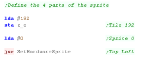
| We're going to use Hardware sprite 0 for the first part - so we
set A to 0... and we loaded our tile patterns into Tile 192... so we
set z_e to 192 We now call our function to set the sprite. |
 |
||||||||||||||||||||||||||||||
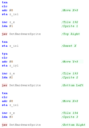
| We need to do the same for the other 3 hardware sprites... We use the X,Y registers we set up before, and add 8 to offset them for the new locations, we also INC z_E to alter the tile number, we set A each time for the hardware sprite numbers
|
 |
| The Code above
works... but waiting for the VBLANK all the time is not a
realistic way of doing things... instead we can allocate 256 bytes
of ram, write changes to the OAM there, then send them all in one
go using a DMA! Lets learn how! |
|
Using a buffer, and copying during Vblank
| Address | Purpose | Bits | Detail |
| 4014h | SPR-RAM
DMA
Register (W) |
HHHHHHHH |
High
byte of ram address to copy to OAM, EG: $02 copies $0200-$02FF |
| Our 'SetHardwareSprite' code is almost the same, just this time
we're storing into the buffer, We'll transfer the data into the actual OAM during our interrupt handler |
 |
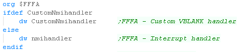
| Address $FFFA of our rom is the interrupt handler We can create an interrupt handler of our own, and put it's address at $FFFA |
 |
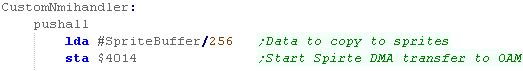
| To copy our buffer of the sprites into the OAM, we just write the
top byte of the buffer address to $4014... So if our buffer is at $0300, we write $03 |
 |

Sprite Definitions - Overview
Sprites use as special bank of 512 bytes of 'OAM' memory for their
definitions... they also use standard VRAM for the pattern data.
In theory the Pattern data can be relocated... but in practice it's best
to just assume it's at $4000 (address in 16 bit words)
Sprites can be various sizes - a 'default size' is set for all sprites...
and certain selected sprites can be double size...
this is, however a bit tricky... lets say you have the default size as
8x8... and one double size 16,16 sprite
If we point this sprite 'double size' 16x16 sprite to pattern 'Tile
0', the 4 8x8 chunks will be made up of tile numbers:
| 1 | 2 |
| 16 | 17 |
| Lets look at this example of a 16x16
sprite in AkuSprite Editor... Akusprite editor is designed for 8x8
sprites, but we can export a 16x16 one in the following way If we want to export this quickly, so we can use it as a single doublesize sprite, one option is to tick the 'FixedSize' tickbox, and set the size to 128,16 This will export the sprite correctly - of course there will be a lot of unused space in the exported file... so we would want to combine all our 16x16 together into a single image |
|
16x16 tiles are
rather a pain... so even though our sprite today is 16x16 - we'll
actually make it up out of 8x8 tiles anyway! |
Sprite Definitions - Ports Used
| Address | Name | Purpose | Bits | Details |
| $2101 | OBSEL | OAM size (Sprite) | SSSNNBBB | S=size N=Bame addr B=Base addr |
| $2102 | OAMADDL/L | OAM address | LLLLLLLL | a=oam address L |
| $2102 | OAMADDL/H | OAM address | R000000H | R= priority Rotation / H=oam address MSB |
| $2104 | OAMDATA | OAM data | ???????? | ????????
Data to write to OAM ram |
| $212C | TM | Main screen designation | ---S4321 | S=sprites 4-1=enable Bgx |
| $2138 | OAMDATAREAD | Read data from OAM | ???????? | ???????? Data read from OAM ram |
Sprite Definitions - OAM Data
Selecting a HL address is done by setting registers $2102 (L) and $2103 (H)
Each address below $0100 holds Two Bytes (The first table)...each address $0100 or above holds just one!... All data is written via the $2104
Note, Sprites use Palettes from 128... so the color palette used is the value in CCC +128
Sprite data should only be written to Vram during Vsync.
| Address | Byte 1 | Byte 2 | Meaning | SprNum |
| $0000 | XXXXXXXX | YYYYYYYY | X=Xpos (bits 0-7) Y=Ypos | 0 |
| $0001 | YXPPPCCCT | TTTTTTTT | Y=yflip X=xflip P=priority compared to BG (C=palette +128) | 0 |
| $0002 | XXXXXXXX | YYYYYYYY | X=Xpos (bits 0-7) Y=Ypos | 1 |
| $0003 | YXPPPCCCT | TTTTTTTT | Y=yflip X=xflip P=priority compared to BG (C=palette +128) | 1 |
| � | � | � | � | � |
| � | � | � | � | � |
| $00FE | XXXXXXXX | YYYYYYYY | X=Xpos (bits 0-7) Y=Ypos | 127 |
| $00FF | YXPPPCCCT | TTTTTTTT | Y=yflip
X=xflip P=priority compared to BG (C=palette +128) T= Tile Pattern
number |
127 |
| $0100 | SXSXSXSX | (no 2nd byte) | S=doubleSize sprite X=Xpos (bit 8) | 0-3 |
| $0101 | SXSXSXSX | (no 2nd byte) | S=doubleSize sprite X=Xpos (bit 8) | 4-6 |
| � | � | � | � | |
| $011F | SXSXSXSX | (no 2nd byte) | S=doubleSize sprite X=Xpos (bit 8) | 124-127 |
Programming a Sprite Example!
| We're going to define a 16x16 sprite... but we'll do it with 4
smaller 8x8 sprites... First we need to define some bitmap data... we used AkuSprite editor to export the sprites, then we need to send the data to VRAM |
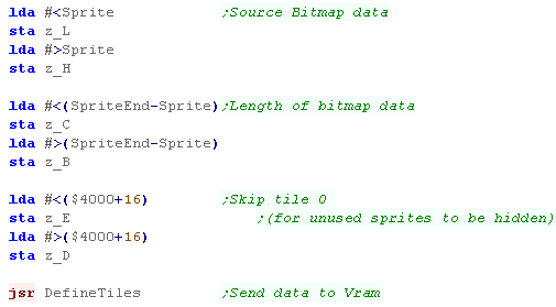 |
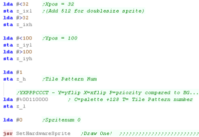
We'll use a 'SetHardwareSprite' function to do the work... we'll look at it in a moment! We need to set the X position in zero page entries z_IXH&L (a 16 bit pair) We need to set the X position in zero page entries z_IYH&L (a 16 bit pair) The Pattern number for the first part one of the sprite is 1... we store it in z_h We need to define the priority of the sprite... we store it in z_l We can also set the palette... NOTE Sprites use palette 128+ Finally we set A to the hardware sprite number... our first part will be sprite 0 (Top Left) |
 |
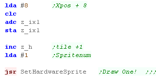
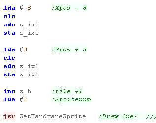
| Now we need to do the 2nd part... We add 8 to the X position,
increase our tile number, and set our hardware sprite to 1. We draw the second part (Top Right) |
 |
| We're going to do the 3rd part... we move the Xpos left 8, and the
Ypos down 8 We increase our tile number again, set our hardware sprite to 2 We draw the third part (Bottom Left) |
 |
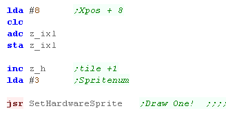
| Last part! We increas the Xpos by 8, Increase the Tilenum again...
and set the hardware sprite to 3 We now draw the last part (Bottom Right) |
 |
| The result can be seen here. |  |
Setting a hardware sprite
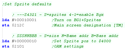
| Ok, Lets look at that SetHardwareSprite function... but first we
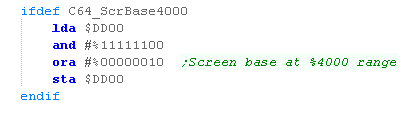
need to set up sprites to work! We need to turn on the sprite layer, and also define the default memory... in these tutorials we have our sprite ram defined as memory address $4000 |
 |
| OK, we're ready to start setting up our sprite... We need to write 4 bytes into the first part of the OAM... the VRAM addresses are 16 bit, so each is 2 bytes... This means we need to double the sprite number to calculate the OAM address for the hardware sprite. We then write the 4 main parameters to the OAM |
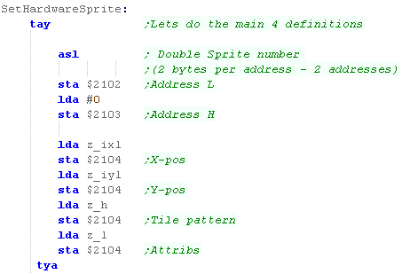 |
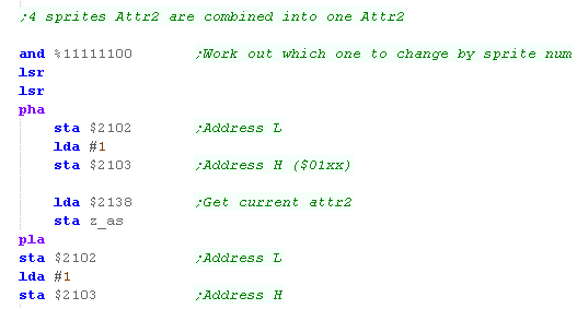
| OK, the next bit is a real pain... The last bit of the Xpos, and the 'Doublesize' parameter for each sprite is combined into a single byte with 4 other sprites!... GRR! We need to work out which address to work with, so we divide the sprite number by 4, and read in from the $01xx range to get the current state of the address (as it holds 3 other sprites info!) |
 |
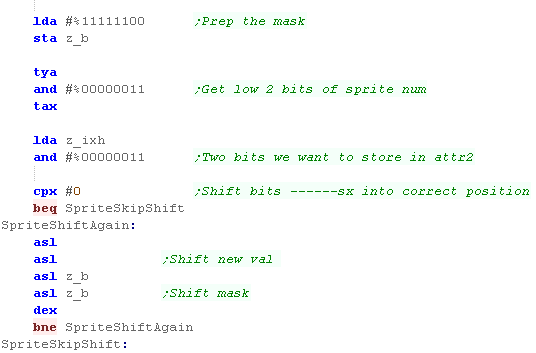
| OK, We need to work out the position of the bits we need to
change, and move the two bits of our passed z_ixh into that
position... To do this we define a 'Mask' - we then shift both the Mask and our data into the correct position depending on the 2 low bits of our sprite number (0-3)... this is because 4 sprites are combined into the same byte |
 |
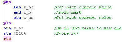
| Now we've got our mask, we use it to clear the 2 bits of the old
value... Now we OR in the new value, and write the result to VRAM... We've finished the sprite! |
 |
|
The SNES is capable
of a large number of 16 color sprites, but it's a little difficult
in some ways, the 16x16 tiles are harder to use than it feels they
should be, and the layout of the OAM makes setting the sprites a
little tricky. Still, the fact we can use 128 hardware sprites onscreen easily is certainly a bonus! |

Technical Details of Hardware Sprites
The Sprite pointers for the bitmap data, are a single byte... multiplying
the sprite pointer by 64 will give the address of the sprite *within the
16k bank of Vram* (so must be in the range $0000-$3FFF)
$1000-$2000 and $9000-$A000 are seen by the VIC as character ROM, so
sprites cannot be in this area!
Sprites are 21 vertical lines and 63 bytes each...
In 1bpp (2 color) mode this makes sprites 24x21...
In 2bpp (4 color) mode they are 12x21...
In both modes, Color 0 is Transparent
In 2bpp mode color 1,2 are read from $D025/6... and color 3 is the sprite
color.
|
We're going to map the screen to the
$4000-$8000 range - out the way of our program (which starts at
$0800) and the rottern character rom (which appears at $1000-$2000
and $9000-$A000) This means we've changed our Font routines, and GetScrPos routine for any bitmap sprite functions as well! |
| Address | Purpose | Bits | Meaning |
| $07F8-$07FF | Sprite pointers (default - will change if screen moved) | SSSSSSSS | s*64=memory address |
| $D000 | Sprite #0 X-coordinate | XXXXXXXX | (only bits #0-#7). |
| $D001 | Sprite #0 Y-coordinate | YYYYYYYY | |
| $D002 | Sprite #1 X-coordinate | XXXXXXXX | (only bits #0-#7). |
| $D003 | Sprite #1 Y-coordinate | YYYYYYYY | |
| $D004 | Sprite #2 X-coordinate | XXXXXXXX | (only bits #0-#7). |
| $D005 | Sprite #2 Y-coordinate | YYYYYYYY | |
| $D006 | Sprite #3 X-coordinate | XXXXXXXX | (only bits #0-#7). |
| $D007 | Sprite #3 Y-coordinate | YYYYYYYY | |
| $D008 | Sprite #4 X-coordinate | XXXXXXXX | (only bits #0-#7). |
| $D009 | Sprite #4 Y-coordinate | YYYYYYYY | |
| $D00A | Sprite #5 X-coordinate | XXXXXXXX | (only bits #0-#7). |
| $D00B | Sprite #5 Y-coordinate | YYYYYYYY | |
| $D00C | Sprite #6 X-coordinate | XXXXXXXX | (only bits #0-#7). |
| $D00D | Sprite #6 Y-coordinate | YYYYYYYY | |
| $D00E | Sprite #7 X-coordinate | XXXXXXXX | (only bits #0-#7). |
| $D00F | Sprite #7 Y-coordinate | YYYYYYYY | |
| $D010 | Sprite #0-#7 X-coordinates | 76543210 | (bit #8) |
| $D015 | Sprite enable register | 76543210 | 1=on |
| $D017 | Sprite double height register | 76543210 | |
| $D01B | Sprite priority register | 76543210 | |
| $D01C | Sprite multicolor mode register | 76543210 | 0=2 color
1=4color |
| $D01D | Sprite double width register | 76543210 | |
| $D01E | Sprite-sprite collision register | 76543210 | |
| $D01F | Sprite-background collision reg | 76543210 | |
| $D025 | Sprite extra color #1 | ----CCCC | |
| $D026 | Sprite extra color #2 | ----CCCC | |
| $D027 | Sprite #0 color | ----CCCC | |
| $D028 | Sprite #1 color | ----CCCC | |
| $D029 | Sprite #2 color | ----CCCC | |
| $D02A | Sprite #3 color | ----CCCC | |
| $D02B | Sprite #4 color | ----CCCC | |
| $D02C | Sprite #5 color | ----CCCC | |
| $D02D | Sprite #6 color | ----CCCC | |
| $D02E | Sprite #7 color | ----CCCC |
Palette
| 0 | 1 | 2 | 3 | 4 | 5 | 6 | 7 |
| 8 | 9 | A | B | C | D | E | F |
Coding to support Hardware Sprites
| We need to store our sprites in the 16k bank with our Screen
Ram... but this will cause us a problem The Stack and Zeropage are $0000-$0200, the screen is at $0400-$0800, our program is at $800+, the Screen Bitmap is at $2000-$4000 - We've not got much memory left! This wouldn't be too bad if $1000-$2000 was free, but it isn't! In the VIC-20 terms this area is used by the Character Rom!... We're going to move the screen to the $4000-$8000 range - out of the way of the program, and the Character rom (it uses $1000-$2000 AND $9000-$A000) We move the screen to $4000-$7FFF by changing bits 0 and 1 of $DD00 to %0000010 We'll need to change our font code to write to the same area, or we won't see our text. |
 |
| We're going to need to alter particular bits of the registers
depending on the sprite number, To facilitate this, we're going to use a lookup table of bits and bitmasks to clear and set the values by sprite number. |
 |
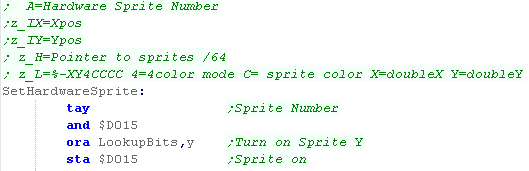
| Ok, we're going to define our SetHardwareSprite function to do the
job of drawing a sprite... First we need to set the correct bit in $D015 - we do this by moving the sprite number to Y, and ORing in the bit from |
 |
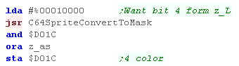
| We're going to use bit 4 from z_L - and set the 4 color mode
accordingly in $D01C To do this we'll use 'C64SpriteConvertToMask'... it will return a mask for the sprite bit in A... and 1 or 0 depending on the bit of z_L anded with A |
 |
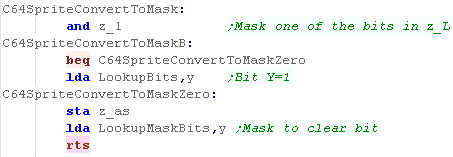
| C64SpriteConvertToMask ANDS in z_L If the result is zero, we set z_as to zero, and load in the mask to keep the bits other than bit Y if the result is one, we set z_as so bit Y is 1, and load in the mask to keep the bits other than bit Y This gives us the function we need! |
 |
| We now want to do the same for $D017 (DoubleHeight) and $D016 (DoubleWidth) using different bits of z_L | 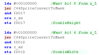 |
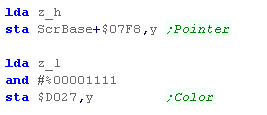
| We're now going to load the 1 byte pointer (Address in VRAM /64)
and save it to $07F8+SpriteNum Next we store the color (in the bottom nibble of z_L) and store it into $D027+SpriteNum |
 |
| We need to store 9 bits of the X position, and we treat the 9th bit in the same way as the other functions , where all these 9th xbits are held in $D010... We use our C64SpriteConvertToMask to do the job, but this time we AND with z_xh | 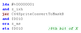 |
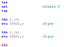
| Ok, we need to write the X and Y position - but these are next to
each other in memory... To write them to the correct addresses, we double the sprite number in Y, and write the Low X byte to $D000+Y and the high byte to $D001+Y Phew! We're finally done! |
 |
Using our function for a test
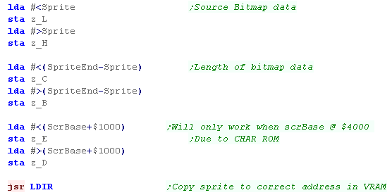
| First we need to copy our sprite data into the correct location in
vram... In our test our Screen base is $4000 - so we'll load the sprites to $5000 we use the LDIR command to copy z_BC bytes from z_HL to z_DE |
 |
| Ok lets set one of the sprites! We set z_IXH/L to the Xpos... We set z_IYH/L to the Ypos we need to calculate the Position in z_h... we take the OFFSET of our sprite (Sprite-Vase= $5000 -$4000=$1000) - and divide this value by 64... Remember, each sprite is 64 bytes in size! All the other settings are in z_L... Sprite Color, XY scaling, and 4 color mode bit. We set A to a number 0-7 to select the hardware sprite we want to change. |
 |
| Here we've drawn two hardware sprites, a streched 4 color one, and 2 color one | 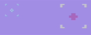 |
| If you want to create valid bitmap data for sprites, you can use my AkuSprite Editor... it's what I used to create the test sprites for this tutorial! | 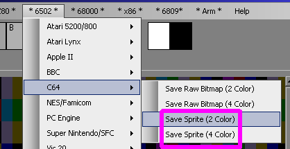 |
|
The C64 is capable of 8
sprites at one time, but if we're very clever, and switch the sprite
data while the screen is drawing, we can up this to 8 sprites per
line? Lets say there's 8 sprites on the top line of the screen... if we move those sprites to the bottom of the screen when the middle is being drawn - we'll double our sprites - we'd have to move them back before the start of the screen is drawn again! It's complex - and beyond the scope of this tutorial, but it's what the best C64 games do to make the most of the hardware! |

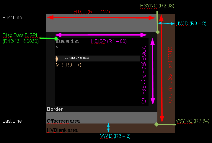
The CRTC Registers
The CRTC 6845 handles the display, it will size and position, and define the memory used by the screen...
In theory there are 17 registers, but in practice ones such as the Lightpen and Cursor registers may not be any use to us... the most interesting registers are marked in Yellow
| Reg
|
Abbrev | Name | Range | Bits | Mode 0 | Mode 1 | Mode 2 | Mode 3 | Mode 4 | Mode 5 | Mode 6 | Mode 7 | Details |
| 0 | HTOT | Horizontal Total | 0-255 | DDDDDDDD | 127
($7F) |
127
($7F) |
127
($7F) |
127
($7F) |
63
($3F) |
63
($3F) |
63
($3F) |
63
($3F) |
Physical width of screen |
| 1 | HDISP | Horizontal Displayed | 0-255 | DDDDDDDD | 80 ($50) | 80 ($50) | 80 ($50) | 80 ($50) | 80 ($50) | 40 ($28) | 40 ($28) | 40 ($28) | Logical width in Chars |
| 2 | HSYNC | Horizontal Sync Position | 0-255 | DDDDDDDD | 98 ($62) | 98 ($62) | 98 ($62) | 98 ($62) | 49 ($31) | 49 ($31) | 49 ($31) | 51 ($33) | Logical Xpos |
| 3 | V/HWID
|
Horiz. and Vert. Sync Widths | 0-15,0-15 | VVVVHHHH | 40 ($28) | 40 ($28) | 40 ($28) | 40 ($28) | 36 ($24) | 36 ($24) | 36 ($24) | 36 ($24) |
Hsync / Vsync area size |
| 4 | VTOT | Vertical Total | 0-127 | -DDDDDDD | 38 ($26) | 38 ($26) | 38 ($26) | 30 ($1E) | 38 ($26) | 38 ($26) | 30 ($1E) | 30 ($1E) | Physical height of screen |
| 5 | VADJ | Vertical Total Adjust | 0-31 | ---DDDDD | 0 ($0) | 0 ($0) | 0 ($0) | 0 ($0) | 0 ($0) | 0 ($0) | 0 ($0) | 0 ($0) | Scanline Offset |
| 6 | VDISP | Vertical Displayed | 0-127 | -DDDDDDD | 32 ($20) | 32 ($20) | 32 ($20) | 25 ($19) | 32 ($20) | 32 ($20) | 25 ($19) | 25 ($19) | Logical Height in Chars |
| 7 | VSYNC | Vertical Sync position | 0-127 | -DDDDDDD | 34 ($22) | 34 ($22) | 34 ($22) | 27 ($1B) | 34 ($22) | 34 ($22) | 27 ($1B) | 27 ($1B) | Logical Ypos of screen |
| 8 | Interlace and Skew | 0-3 | ------DD | 1 ($1) | 1 ($1) | 1 ($1) | 1 ($1) | 1 ($1) | 1 ($1) | 1 ($1) | 2 ($2) |
0/2=off 1/3=on | |
| 9 | MR | Maximum Raster Address | 0-31 | ---DDDDD | 7 ($7) | 7 ($7) | 7 ($7) | 9 ($9) | 7 ($7) | 7 ($7) | 9 ($9) | 18 ($12) | Scanlines per Char row |
| 10 | Cursor Start Raster | 0-127 | -DDDDDDD | 0 | 0 | 0 | 0 | 0 | 0 | 0 | 0 | Unneeded | |
| 11 | Cursor End Raster | 0-31 | ---DDDDD | 8 ($8) | 8 ($8) | 8 ($8) | 9 ($9) | 8 ($8) | 8 ($8) | 9 ($9) | 19 ($13) | Unneeded | |
| 12 | DISPH | Display Start Address | 0-63 | --HHHHHH | 8 ($8) | 8 ($8) | 8 ($8) | 8 ($8) | 8 ($8) | 8 ($8) | 8 ($8) | 8 ($8) | Screen Address H |
| 13 | DISPL | Display Start Address | 0-255 | LLLLLLLL | 48 ($30) | 48 ($30) | 48 ($30) | 48 ($30) | 48 ($30) | 48 ($30) | 48 ($30) | 48 ($30) | Screen Address L |
| 14 | CURH | Cursor Address H | 0-63 | --HHHHHH | 0 | 0 | 0 | 0 | 0 | 0 | 0 | 0 | unused |
| 15 | CURL | Cursor Address L | 0-255 | LLLLLLLL | 0 | 0 | 0 | 0 | 0 | 0 | 0 | 0 | unused |
| 16 | LPH | Light Pen Address | 0-63 | --HHHHHH | 0 | 0 | 0 | 0 | 0 | 0 | 0 | 0 | Read Only |
| 17 | LPL | Light Pen Address | 0-255 | LLLLLLLL | 0 | 0 | 0 | 0 | 0 | 0 | 0 | 0 | Read Only |
| The Various registers will define the width, height and starting
position of the screen. Each screen mode will have a set of recommended registers settings (shown in the chart above), but we can resize the screen in some cases to make a smaller screen - and we may wish to do this to save memory if we don't need a 'full size' screen. By altering Reg12 we can effect hardware page flipping with Double Buffering - by allocating one memory area for a visible buffer, and a second for the drawing area, we can make sure the viewer won't see the screen redraw. In addition, we can alter Reg12+13 to effect a Horizontal or Vertical Hardware scroll - but this will expose other areas of Ram, which weren't used by the screen before. |
 |
| Beware! While
BeebEM recrates some of the registers - it seems it does not
'accurately' emulate a real monitor... some of the settings which
may work fine on the emulator, may not work correctly on a real
BBC (or may risk damage to the display in the worst situations.) |
|
Using and Testing the registers!
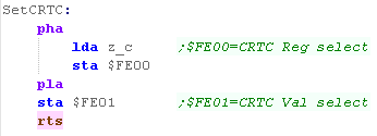
| We're going to define a function called SetCRTC - it will use A as
the new value for CRTC register z_C We select a register using $FE00 - then set the new value for that register with $FE01 |
 |
| We're not going to look at the program code - it's long and not
particularly related to the CRTC - what it does is let us see the
changes to each register onscreen! To use it, compile 'BBC_CRTC_Test.asm' |
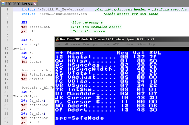 |
| On the left are two
letters - these are keys you can press to change the
register - for example J and K will change the address of the start
of the screen! Try the keys - you'll see the settings in VAL (decimal) and &VL (hex) and the effect onscreen! |
 |
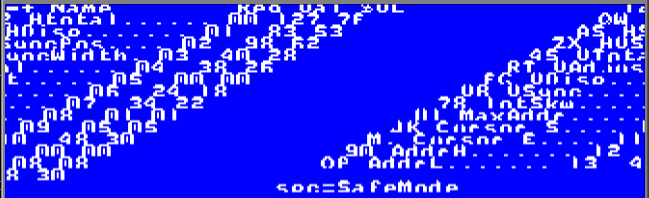
| Because our text drawing code hasn't changed, Altering AddrH will make the screen look weird - we'd need to reprogram our drawing code to accommodate our new settings to make it all work seamlessly.. | 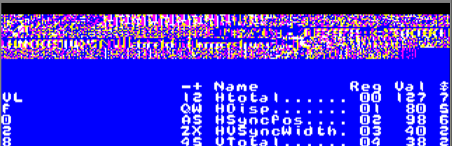 |
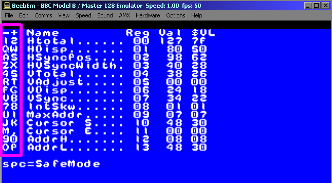
| It's very easy to use some setting that are impossible to view,
and now we can't see the settings any more! The tool has a Safe Mode to get around this... Press Space... this will turn on safe mode! In Safe Mode, the settings you choose will be applied for an instant, and then it will flip back to the defaults - so you can see the effect of the settings you chose, and still see all the options on a normal screen |
 |
|
This program
just allows you to test what each register does - and find
suitable settings for the screen size and position you need... Once you've done that, you'll need to reprogram your sprite, font and other drawing routines to work with the new screen position and orientation. |

Character Map
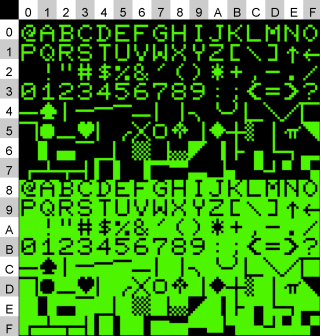
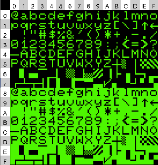
The PET has a character map of 128 characters... when the top bit (bit 7) is 1, these characters will be inverted - we'll need to use a combination of both for the block graphics.
The early PET had a single upper case character map... later systems had a second character map with lower case... The block characters used in this lesson exist in both.
We can switch between the two by writing to register $E84C...
| Write #12 to $E84C
|
Write #14 to $E84C
|
VRAM Addresses
| The screen is 40x25 characters... or 80x25 on later models. Putting a character onscreen is easy!... we just write a character to memory address $8000 onwards. Our formula for an address on the 40 char wide screen is Vram Address = $8000+(Ypos*40)+Xpos Our formula for an address on the 80 char wide screen is Vram Address = $8000+(Ypos*80)+Xpos |
 |
| When we want to move down a line, we just add 40 or 80 to our memory address. | 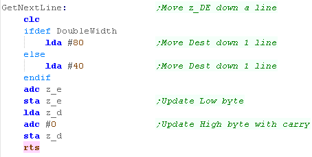 |
The character blocks
| if we imagine the character block as 4 pixels in a 2x2 grid, there
are 16 possible combinations. Here are the 16 - Shown separated by 'Club' symbols. |
 |
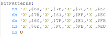
| Here is the bytes that produce this pattern. The character numbers for these are a bit erratic... the ones >$80 are inverted - we have to invert half the characters to make the patterns we need. Note, the 'club' character here is ASCII 'X' |
 |
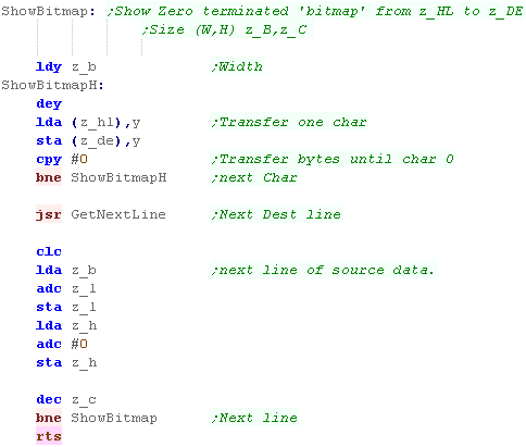
Showing our 'bitmap'
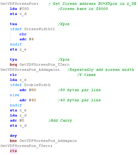
| Here is the routine we'll use to show a bitmap. It's pretty simple, it copies lines of bytes from the source to screen ram, moving down a line after each line. |
 |
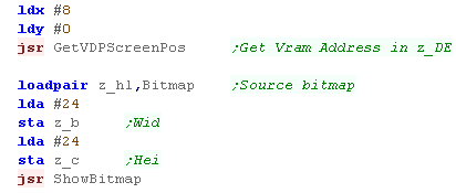
| When we want to show a bitmap, we first calculate the destination
address in Vram with GetVDPScreenPos, We then specify the source data into zero page pair z_hl, and specify our bitmap size before using ShowBitmap. |
 |
| Here is the result! | 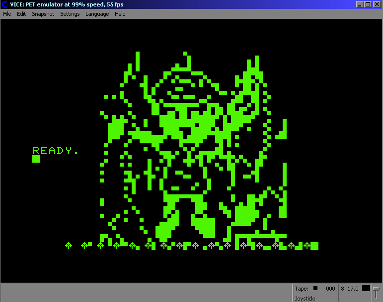 |
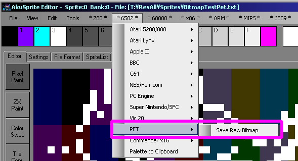
| If you want to create a 'bitmap' for the PET, you can do it with
my Akusprite
editor. It will take a bitmap, and covert it to bytes that represent the correct characters - it's what was used for this tutorial!. |
 |
|
The PET doesn't have any graphics modes that
can do bitmaps, and unlike its successor the VIC-20, it also
cannot have 'redefined' character codes. We'll have to make do with these characters in the charset for any 'game graphics'... but that's kind of the charm of these old systems! |
The PET Keyboard
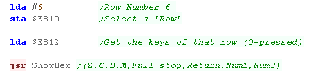
| The Keyboard of the pet is split into 10 'Blocks' (0-9)... we
select one of these by writing to memory mapped port $E810,
We then read from $E812 - this will return the state of each of the keys in that block ('Row' of the key matrix) - each key will be represented by one bit... a value of 1 means that key is not pressed... a value of 0 means the key is pressed! For example... Suppose we want test the Return key... this is in group 6, so we write #6 to port $E810... we then read back from $E812 - among the other keys, Bit 5 (PB5) will represent the state of Return... this row also includes Z,C,B,M,Full stop, Num1 and Num3 ! |
 |
The keys matrix layout is shown below: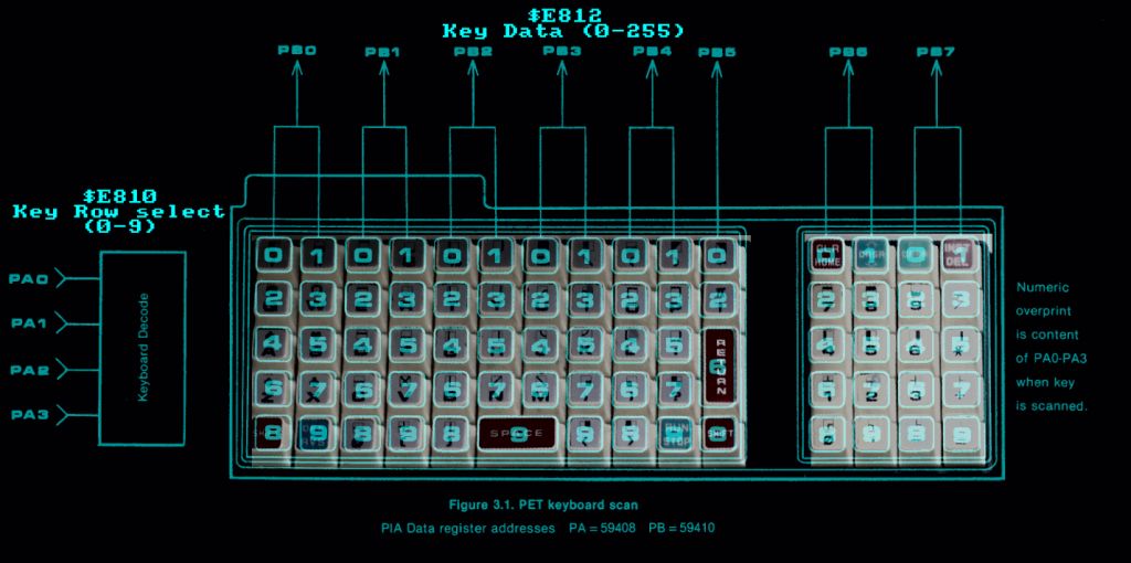
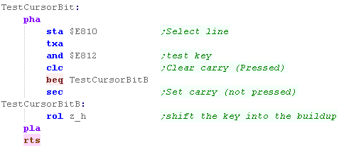
Simulating a joystick
| We're going to read in the numpad, and use 8,2,4 and 6 as
directions so we can port Y-quest and Grime to the PET We're going to create a function called "TestCursorBit" - this will test a bitmask in X of row A , and shift a bit into zero page entry z_H |
 |
| We'll use this function to read in the 4 directions, and space and enter as fire buttons! | 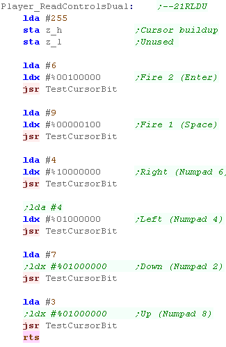 |
| The PET didn't come
with a joystick port, however it is possible make a converter and
connect one via the parallel port. However, for simplicity, we'll stick to the built in keyboard for our game-controller needs! |
|
PET Sound!
The PET is capable of up to 4 octaves... one of 3 possible pairs can be
selected with $E84A.
Address $E84B will turn the sound on or off... we
write #16 to turn it on, #0 to turn it off.
Address $E84A can be used to select the Octave with
value 15/51/85
Address $E848 can be used to select the note, a
value of 64-255 should be passed.
It is not possible to set the volume, or play multiple tones at the same
time.
| Note Freq | octave=15 | octave=51 | octave=85 | |||
| Octive 0 | Octive 1 | Octive 1 | Octive 2 | Octive 2 | Octive 3 | |
| B | 251 | 125 | 251 | 125 | 251 | 125 |
| C | 238 | 118 | 238 | 118 | 238 | 118 |
| C# | 224 | 110 | 224 | 110 | 224 | 110 |
| D | 210 | 104 | 210 | 104 | 210 | 104 |
| D# | 199 | 99 | 199 | 99 | 199 | 99 |
| E | 188 | 93 | 188 | 93 | 188 | 93 |
| F | 177 | 88 | 177 | 88 | 177 | 88 |
| F# | 168 | 83 | 168 | 83 | 168 | 83 |
| G | 158 | 78 | 158 | 78 | 158 | 78 |
| G# | 149 | 74 | 149 | 74 | 149 | 74 |
| A | 140 | 69 | 140 | 69 | 140 | 69 |
| A# | 133 | 65 | 133 | 65 | 133 | 65 |
(Sound info taken from the PetFaq)
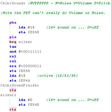
Sfx with Chibisound!
| These tutorials use a sound 'driver' called ChibiSound, Chibisound uses a single byte parameter in the Accumulator, and provides 64 different pitches, in low or high volume with either tones or noise. Sending a value of 0 mutes sound, all other values make a tone... Chibisound is intended to make it simple to have SFX in multiplatform games and was used in Grime Z80 and Grime 6502 |
|
Writing Chibi Sound!
| We turn the sound on or off with $E84B. We select our tone with $E848... Chibisound only uses one octive, setting $E848=15 |
 |
|
Now we've got graphics, sound and input
routines we can port Yquest and Grime to the PET! We'll have to use graphics characters for our game graphics! |
| We have to use Ascii characters for all the graphics of Yquest and Grime. |  |
| Rather than sprite bitmap data, these games use a 'list' of graphics characters to use for each object and frame of animation. |  |
| View Options |
| Default Dark |
| Simple (Hide this menu) |
| Print Mode (white background) |
| Top Menu |
| ***Main Menu*** |
| Youtube channel |
| Patreon |
| Introduction to Assembly (Basics for absolute beginners) |
| Amazon Affiliate Link |
| AkuSprite Editor |
| ChibiTracker |
| Dec/Bin/Hex/Oct/Ascii Table |
| Alt Tech |
| Archive.org |
| Bitchute |
| Odysee |
| Rumble |
| DailyMotion |
| Please note: I wlll upload more content to these alt platforms based on the views they bring in |
| 68000 Content |
| ***68000 Tutorial List*** |
Learn 68000 Assembly  |
| Hello World Series |
| Platform Specific Series |
| Simple Samples |
| Grime 68000 |
| 68000 Downloads |
| 68000 Cheatsheet |
| Sources.7z |
| DevTools kit |
| 68000 Platforms |
| Amiga 500 |
| Atari ST |
| Neo Geo |
| Sega Genesis / Mega Drive |
| Sinclair QL |
| X68000 (Sharp x68k) |
| 8086 Content |
| Learn 8086 Assembly |
| Platform Specific Series |
| Hello World Series |
| Simple Samples |
| 8086 Downloads |
| 8086 Cheatsheet |
| Sources.7z |
| DevTools kit |
| 8086 Platforms |
| Wonderswan |
| MsDos |
| ARM Content |
| Learn ARM Assembly |
| Learn ARM Thumb Assembly |
| Platform Specific Series |
| Hello World |
| Simple Samples |
| ARM Downloads |
| ARM Cheatsheet |
| Sources.7z |
| DevTools kit |
| ARM Platforms |
| Gameboy Advance |
| Nintendo DS |
| Risc Os |
| Risc-V Content |
| Learn Risc-V Assembly |
| Risc-V Downloads |
| Risc-V Cheatsheet |
| Sources.7z |
| DevTools kit |
| MIPS Content |
| Learn Risc-V Assembly |
| Platform Specific Series |
| Hello World |
| Simple Samples |
| MIPS Downloads |
| MIPS Cheatsheet |
| Sources.7z |
| DevTools kit |
| MIPS Platforms |
| Playstation |
| N64 |
| PDP-11 Content |
| Learn PDP-11 Assembly |
| Platform Specific Series |
| Simple Samples |
| PDP-11 Downloads |
| PDP-11 Cheatsheet |
| Sources.7z |
| DevTools kit |
| PDP-11 Platforms |
| PDP-11 |
| UKNC |
| TMS9900 Content |
| Learn TMS9900 Assembly |
| Platform Specific Series |
| Hello World |
| TMS9900 Downloads |
| TMS9900 Cheatsheet |
| Sources.7z |
| DevTools kit |
| TMS9900 Platforms |
| Ti 99 |
| 6809 Content |
| Learn 6809 Assembly |
| Learn 6309 Assembly |
| Platform Specific Series |
| Hello World Series |
| Simple Samples |
| 6809 Downloads |
| 6809/6309 Cheatsheet |
| Sources.7z |
| DevTools kit |
| 6809 Platforms |
| Dragon 32/Tandy Coco |
| Fujitsu FM7 |
| TRS-80 Coco 3 |
| Vectrex |
| 65816 Content |
| Learn 65816 Assembly |
| Hello World |
| Simple Samples |
| 65816 Downloads |
| 65816 Cheatsheet |
| Sources.7z |
| DevTools kit |
| 65816 Platforms |
| SNES |
| eZ80 Content |
| Learn eZ80 Assembly |
| Platform Specific Series |
| eZ80 Downloads |
| eZ80 Cheatsheet |
| Sources.7z |
| DevTools kit |
| eZ80 Platforms |
| Ti84 PCE |
| IBM370 Content |
| Learn IBM370 Assembly |
| Simple Samples |
| IBM370 Downloads |
| IBM370 Cheatsheet |
| Sources.7z |
| DevTools kit |
| Super-H Content |
| Learn SH2 Assembly |
| Hello World Series |
| Simple Samples |
| SH2 Downloads |
| SH2 Cheatsheet |
| Sources.7z |
| DevTools kit |
| SH2 Platforms |
| 32x |
| Saturn |
| PowerPC Content |
| Learn PowerPC Assembly |
| Hello World Series |
| Simple Samples |
| PowerPC Downloads |
| PowerPC Cheatsheet |
| Sources.7z |
| DevTools kit |
| PowerPC Platforms |
| Gamecube |
| Work in Progress |
| ChibiAndroids |
| Misc bits |
| Ruby programming |
Buy my Assembly programming book
on Amazon in Print or Kindle!


Available worldwide!
Search 'ChibiAkumas' on
your local Amazon website!
Click here for more info!


Buy my Assembly programming book
on Amazon in Print or Kindle!
Available worldwide!
Search 'ChibiAkumas' on
your local Amazon website!
Click here for more info!
Buy my Assembly programming book
on Amazon in Print or Kindle!
Available worldwide!
Search 'ChibiAkumas' on
your local Amazon website!
Click here for more info!
Buy my Assembly programming book
on Amazon in Print or Kindle!
Available worldwide!
Search 'ChibiAkumas' on
your local Amazon website!
Click here for more info!
Buy my Assembly programming book
on Amazon in Print or Kindle!
Available worldwide!
Search 'ChibiAkumas' on
your local Amazon website!
Click here for more info!
Buy my Assembly programming book
on Amazon in Print or Kindle!
Available worldwide!
Search 'ChibiAkumas' on
your local Amazon website!
Click here for more info!
Buy my Assembly programming book
on Amazon in Print or Kindle!
Available worldwide!
Search 'ChibiAkumas' on
your local Amazon website!
Click here for more info!
Buy my Assembly programming book
on Amazon in Print or Kindle!
Available worldwide!
Search 'ChibiAkumas' on
your local Amazon website!
Click here for more info!
Buy my Assembly programming book
on Amazon in Print or Kindle!
Available worldwide!
Search 'ChibiAkumas' on
your local Amazon website!
Click here for more info!
Buy my Assembly programming book
on Amazon in Print or Kindle!
Available worldwide!
Search 'ChibiAkumas' on
your local Amazon website!
Click here for more info!
Buy my Assembly programming book
on Amazon in Print or Kindle!
Available worldwide!
Search 'ChibiAkumas' on
your local Amazon website!
Click here for more info!