

Platform Specific Lessons
Introduction to the Platform
Specific Series...
In this series of tutorials we're going to cover how to do simple common tasks on multiple 6502 systems...
The lessons will cover how to do each task (where possible) on all the systems and create functions that can be called in a common way, so we will create a 'common library' of functions you can use in your own programs to write platform independent 6502 code...
You should know 6502 already, If you don't please go through the Basic 6502 Assembly Lessons first!
Each lesson will have a matching Video tutorial, and if you just want the code, you can skip knowing how it works, and just download the code!
Enough talk, let's start creating code, and put those 6502 machines to work!


Screen Layout on the BBC
Screen Setup on the BBC
Setting up the screen on the BBC requires configuring the CRTC to define the size and position of the screen with $FE00 (control) and $FE01 (data), and the ULA, which sets the graphics mode with $FE20 (mode), and colors with $FE21 (colors)
The way we set up the colors is rather odd, we need to define 16 definitions that map bit layouts to colors - in 4 color mode this means we have to set 4 settings to the same color to have the screen work as we'd expect!... we'll see this later!
Lets set up the screen!
Drawing to the screen
Using these functions!
Hardware Addresses
The Screen on the Atari 800 and Atari 5200 is defined by a 'Display list' ... this defines the screen mode of each line of the screen... in theory we could change modes on various lines, like the Enterprise 128, but really we just want it to be the same the whole time...
We'll need to use the GTIA and ANTIC to control the screen... but unfortunately the GTIA is mapped to different memory addresses on the 5200 and 800:
Here are the registers we're going to use:
Screen Modes
The Atari 800 & 5200 have a variety of modes - we can change mode every line of the screen - but some modes are 'taller' than others... here are the options - note: we're only going to look at modes E and F in these tutorials
Defining our Display List
We need to use a variety of commands to define our Display list:
There are a variety of rules we need to obey when we create our Display List
1. The display list must not cross over a 1k boundary (align on a byte boundary)
2. The screen data cannot go over a 4k boundary UNLESS you manually restart the memory position with $4x $BB $AA
3. The display list must start with three $70 commands for VBLANK
4. The list must end with $41 $BB $AA... where $AABB is a pointer to the start of the list.
Setting up our base palette
Calculating screen memory position with GetScreenPos
Showing the bitmap to the screen
Highres Screen - Screen Colors
Highres Screen Mode 2 - Memory map
Initializing the screen
GetScreenPos to select memory location by XY co-ordinate
Drawing a bitmap to the screen
Lynx Graphics
Graphics Hardware Settings
Setting up Screen Memory
Calculating memory position by X,Y pos
Drawing to the screen
The PC-Engine Graphics system
Graphics Registers
There are a variety of Graphics registers, but at this time the main ones we'll need are 0 (Select WRITE) and 2 (Data), these will allow us to write data to the Vram
Vram Layout
Initializing the Screen
Drawing our bitmap
VRAM functions
Getting Tiles to the screen
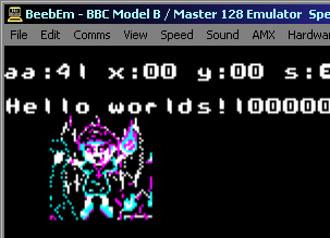
| The screen layout on the BBC is
not the same as used by most other systems (though is used on
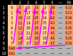
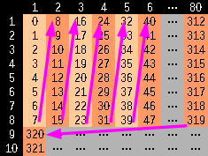
the C64)... The screen is split up into 8 pixel tall strips... and these are stored in memory Y first... then X Lets imagine we write bytes to consecutive memory addresses (displayed as 0-641 in the diagram to the right)... when we write to the first 8 pixels, they go DOWN the screen... but the 9th pixel will go back up to the top of the strip This will continue untill the far right of the screen... then the next byte will be the far left of the next 8 pixel tall strip. |
 |
| These
tutorials will currently only cover Mode 1 - which offers
320x200 4-color bitmap graphics - at this time the other
screen modes won't be covered... The reason for this is that the screen resolution and color depth makes it good for games - but it uses a lot of memory - so it's not suitable for 16k machines... We may cover other screen modes later - but for now we're just going to cover this one! |
 |
Screen Setup on the BBC
Setting up the screen on the BBC requires configuring the CRTC to define the size and position of the screen with $FE00 (control) and $FE01 (data), and the ULA, which sets the graphics mode with $FE20 (mode), and colors with $FE21 (colors)
The way we set up the colors is rather odd, we need to define 16 definitions that map bit layouts to colors - in 4 color mode this means we have to set 4 settings to the same color to have the screen work as we'd expect!... we'll see this later!
|
|
 |
This tutuorial uses Mode 1 (320x256 @ 4 color)... however depending on your requirements you may prefer to use Mode 5 (160x256 @ 4 color) or Mode 4 (320x256 @ 2 color)... it will just depend on your graphical requirements and how much memory you can spare! |
Lets set up the screen!
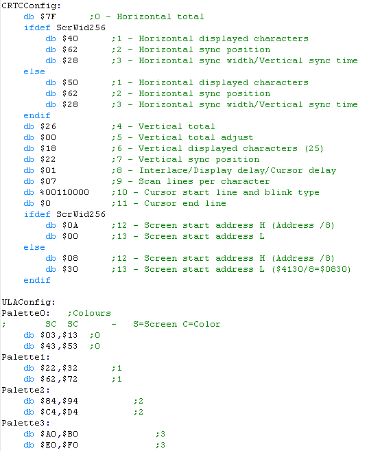
| We're going to need to define the
settings we want to use for our screen layout and colors... The values shown here will set up a screen 320x200 or 256x192, and set a 4 color palette with a blue background The Color definitions are odd!... each Byte is spilt onto two nibbles which we'll call $SC... S is the screen nibble (Logical color), and C is the resulting color (physical color) - selected from the EOR column in the chart shown above... We should set all 4 of the C nibbles to the same color for a 'normal screen... if we do not - opposite columns will have different colors, or pixels with different colored neighbors will be strange - try different settings to see what happens! Note registers 12 and 13... these define the memory address of the screen - however for reasons unknown, you have to divide the address by 8... we've mapped the 256 pixel wide to $5000... or the 320 pixel wide one to $4130 - so the screen goes up to the $8000 area (the top address on a 32k machine) |
 |
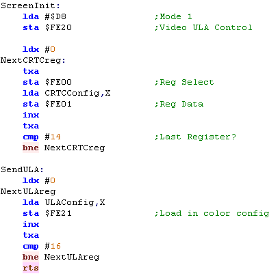
| When it comes to setting up the
screen we need to send the bytes to the hardware... When we want to set CRTC registers, we send the register number we want to set to address $FE00, and we send the data for that register to $FE01 This will set up the Screen position. Next we need to set the Screen mode - we select Mode 1 by sending $D8 to address $FE20 Finally, we need to set up the colors, we do this by sending 16 bytes to $FE21 to define the color layout onscreen. |
 |
 |
It doesn't look like the Horizontal and
Vertocal sync registers have any effect on BeebEM ... it seems
like maybe these aren't supported by the emulator? The values here should work, but the author of these tutorials doesn't own a BBC so it's not been tested on real hardware!... feel free to donate one if you're not happy with that! |
Drawing to the screen
| We're going to draw our Chibiko
character to the screen! - we can convert a bitmap into the
correct format for the BBC screen. We can just write data to video ram to draw, but we need a way of working out the correct location to draw to... we'll define a function called GetCursorPos This will take an X,Y position (in bytes) in the X and Y registers and will set a Zero Page pair Z_DE to the destination screen address... We can then write out bytes to that address to draw our bitmap! |
 |
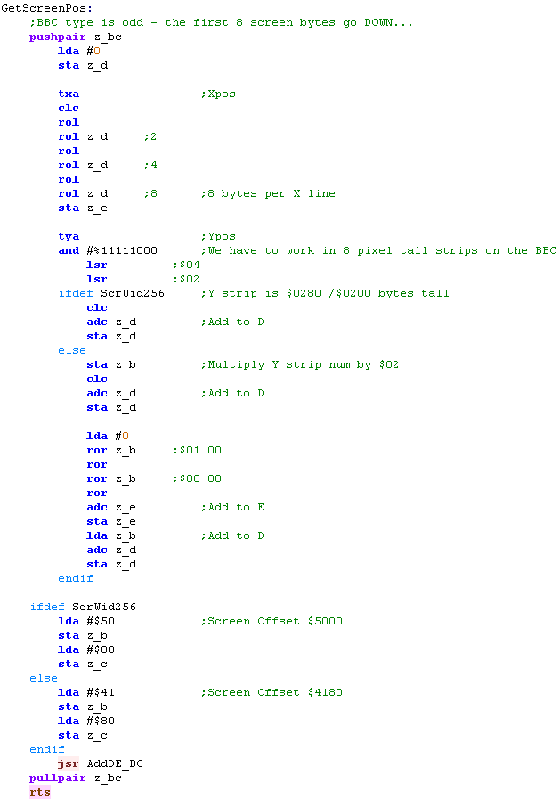
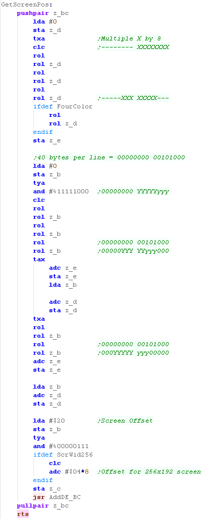
| The GetScreenPos function is
pretty long, but the concept is pretty simple... First we take the Xpos and we multiply it by 8 - this is because there's 8 lines of bytes between each column, due to the way the screen is structured... On a 320 pixel wide screen, each strip of 8 lines is $280 bytes wide... on the 256 pixel wide screen it's $200 (which is much easier to calculate!) We ignore the bottom 3 bits of the Y line - to get the 'strip' number - then multiply this by either $280 or $200 to get the offset - we do this by bitshifting the Y pos into the $02 and $08 (in the case of 320 screens) , and save these in zero page Z_DE Finally we add the start address of the screen... the settings we're using map it to the top of the memory area - so we either add $5000 (for the 256 pixel screen) or $4180 (for the 320 pixel screen) |
 |
| If we're within an 8 line strip, we can move down a line just
by INCing DE Really this is just here for compatibility with other systems! |
 |
| Note: Because the BBC works in 8 pixel tall strips, the GetScreenPos function ignores the bottom 3 bits of the Y line - if you need that functionality, you can add it to the function - of course, this would make the function slightly slower, but if it's what you need, then go for it! |  |
Using these functions!
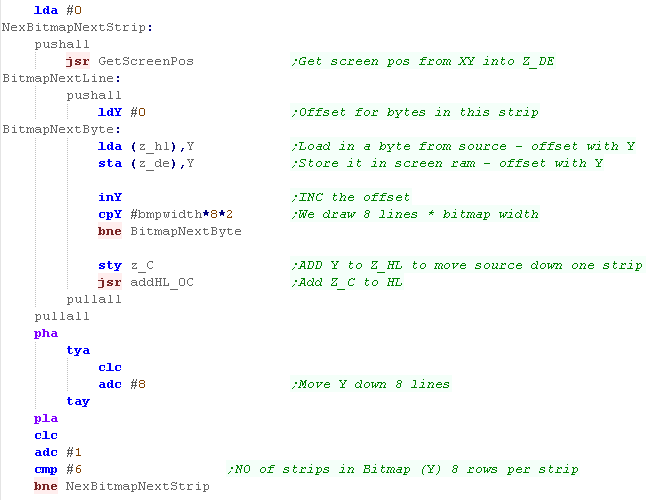
| We're going to use Z_HL as the source data of our bitmap | 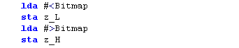 |
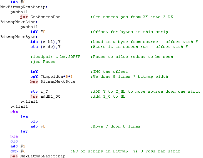
| When it comes to drawing the bitmap, we're going to do it in 8
pixel tall 'Strips' to match the screen layout... At the start of each strip, we're going to use GetScreenPos to work out the position to write to... we're then going to write bytes from Z_HL (the bitmap) to Z_DE (the screen) using Y as an offset count... Once we've written all the bytes within this strip, we'll move Y down 8 lines, update Z_HL to move past the data we've just copied We now reapeat the procedure until the bitmap is drawn! |
 |
 |
Warning!
This routine uses Y as a counter for bytes within the current
strip... that means this function will only work for a bitmap
upto 32 bytes (128 pixels) wide... if you need more - you're
going to have to do the work yourself! What? you want it ALL doing for you? - yeah good luck with that! |

Hardware Addresses
The Screen on the Atari 800 and Atari 5200 is defined by a 'Display list' ... this defines the screen mode of each line of the screen... in theory we could change modes on various lines, like the Enterprise 128, but really we just want it to be the same the whole time...
We'll need to use the GTIA and ANTIC to control the screen... but unfortunately the GTIA is mapped to different memory addresses on the 5200 and 800:
| Atari 5200 | Atari 800 | |
| Cart ROM | $4000 | $A000 |
| GTIA (Graphics) | $C000 | $D000 |
| POKEY (Sound) | $E800 | $D200 |
| PIA | Not present | $D300 |
| ANTIC | $D400 | $D400 |
Here are the registers we're going to use:
| Name | Description | Address A80 | Address A52 |
| COLPF0 | Color/brightness of setcolor 0 | $D016 | $C016 |
| COLPF1 | color/brightness of setcolor 1 | $D017 | $C017 |
| COLPF2 | color/brightness of setcolor 2 | $D018 | $C018 |
| COLPF3 | color/brightness of setcolor 3 | $D019 | $C019 |
| COLBK | color/brightness of setcolor 4 | $D01A | $C01A |
| DMACTL | Direct Memory access control (DMA) | $D400 | $D400 |
| DLISTL | display list pointer low byte | $D402 | $D402 |
| DLISTH | display list pointer high byte | $D403 | $D403 |
Screen Modes
The Atari 800 & 5200 have a variety of modes - we can change mode every line of the screen - but some modes are 'taller' than others... here are the options - note: we're only going to look at modes E and F in these tutorials
| Antic
Mode |
Basic
Mode |
Colors | Lines | Width | Bytes
per
Line |
Screen
Ram
(Bytes) |
| 2 | 0 | 2 | 8 | 40 | 40 | 960 |
| 3 | N/A | 2 | 10 | 40 | 40 | 760 |
| 4 | N/A | 4 | 8 | 40 | 40 | 960 |
| 5 | N/A | 4 | 16 | 40 | 40 | 480 |
| 6 | 1 | 5 | 8 | 20 | 20 | 480 |
| 7 | 2 | 5 | 16 | 20 | 20 | 240 |
| 8 | 3 | 4 | 8 | 40 | 10 | 240 |
| 9 | 4 | 2 | 4 | 80 | 10 | 480 |
| A | 5 | 4 | 4 | 80 | 20 | 960 |
| B | 6 | 2 | 2 | 160 | 20 | 1920 |
| C | N/A | 2 | 1 | 160 | 20 | 3840 |
| D | 7 | 4 | 2 | 160 | 40 | 3840 |
| E | N/A | 4 | 1 | 160 | 40 | 7680 |
| F | 8 | 2 | 1 | 320 | 40 | 7680 |
Defining our Display List
We need to use a variety of commands to define our Display list:
| Command | Function |
| $x0-$xF | Screen mode change |
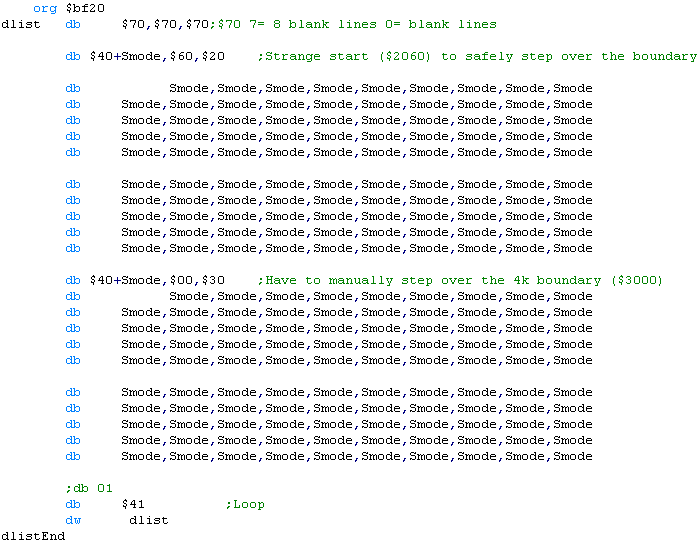
| $70 | 8 Blank lines |
| $4x $BB $AA | Start Screen mode x at address $AABB |
| $41 $BB $AA | Wait for Vblank, and restart display list at $AABB |
There are a variety of rules we need to obey when we create our Display List
1. The display list must not cross over a 1k boundary (align on a byte boundary)
2. The screen data cannot go over a 4k boundary UNLESS you manually restart the memory position with $4x $BB $AA
3. The display list must start with three $70 commands for VBLANK
4. The list must end with $41 $BB $AA... where $AABB is a pointer to the start of the list.
| Here's the display list we'll be
using! We're defining the definition at the end of our rom, so that it won't go over a 1k boundary... We're using the 'smode' symbol for our screen mode - this will support mode E or F - as they use the same amount of screen ram... Notice, half way through the definition we're using $40 to restart the screen ram - we have to do this because our 7K screen MUST go over a 4K boundary, and the screen will wrap unless we manually step into the $3000 address... |
 |
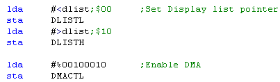
| When we want to start the screen, we need to load the display
list address into $D402 (DLISTH/L) We then need to start the screen processing the list, by writing %00100010 to $D400 (DMACTL) |
 |
|
This template will work for screen modes E or F - but if you want to use different modes, or you want to change mode midscreen, you'll want to write a new one... just make sure you follow the rules, and you should be OK! |
Setting up our base palette
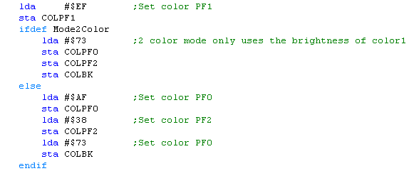
| We'll be using 2 and 4 color mode
on the Atari... 4 color mode is pretty straightforward, but 2 color mode is a bit odd... In 2 color mode only the BRIGHTNESS of the 2nd color is used - they'll both be the same color as the background! |
 |
| Colors on the
Atari will differ depending on if you're using PAL or NTSC...
there also seems to be an inconsistency in the way Atari800win and Jum52 work with 2 color mode - but this may be a bug in the emulator! |
|
Calculating screen memory position with GetScreenPos
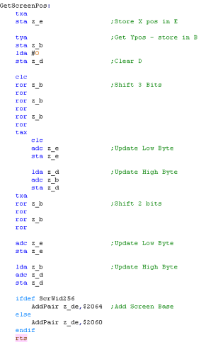
| We're going to calculate the screen position - each line of the screen is 40 bytes, and our screen starts at $2060... so our calculation for the screen position is $2060+(40*Ypos)+Xpos |
|
||||||||||||||||||||||||||||||||||||||||||||||||||||||||||||||||||||||||||||||||||||||||||||||||||||||||||||
| When we call this function,
register X will be the Xpos, and Y will be the Ypos We start by moving X into zeropage address z_e Next we'll move Y into z_b, and set z_d and A to zero We're now going to shift 3 bits from z_b to A... we'll add this to z_de Then we'll shift another 2 bits from z_b to A... we'll add this to z_de as well... we've now effectively added Y*40 Now we add the screen base... this completes the address calculation |
 |
||||||||||||||||||||||||||||||||||||||||||||||||||||||||||||||||||||||||||||||||||||||||||||||||||||||||||||
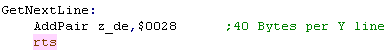
| As the lines are directly beneath each other in memory, we
just add 40 to move down a line When we want to move down a line, we just add 40 to the current position |
 |
|
Doing the
'Multiplication' by bitshifts is confusing to look at but it's
faster... Using a loop with Y and repeatedly calling GetNextLine would work and be simpler, but it would be much slower! |
Showing the bitmap to the screen
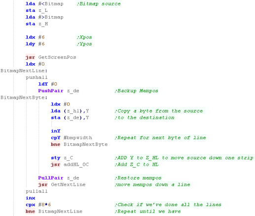
| We're going to use z_hl to point
to the source bitmap. We'll use GetScreenPos to set z_de to the destination When we want to get a bitmap onto the screen we'll use Y as an offset to copy each line from the source to the destination.... We'll then move down a screen line by using GetNextLine... and we'll add Y to HL to move the source data for the next line... we'll repeat the procedure until we've don all the lines. |
 |

Highres Screen - Screen Colors
| Colors on the Apple II are effectively an 'Artifact' of the
screen... certain combinations of Off (0) and On (1) pixels will appear colored... this is known as Composite Artifact colors... Unlike pretty much every system in existance, 8 bits of a byte draw 7 pixels!.... the top bit is a 'Color bit'... selecting 'Palette 0 or 1 The remaining 7 bits are the 7 pixels of bitmap data... because each line is 40 bytes wide, the Apple II screen is a rather odd resolution of 280�192 |
|
||||||||||||||||||||||||||||||||||||||
| Because of these artifacts, a '2 color' bitmap will show
colors depending on the combination of the pixels... My Akusprite editor offers a half horizontal resolution mode, where the 4 colors will be converted to the correct bit combinations |
|
||||||||||||||||||||||||||||||||||||||

|
It's important to understand there isn't
a separate 2 and 4 color mode, it's just the combination of
pixels that will appear different colors... AkuSprite Editor halves horizontal resolution when exporting 4 colors... but If you're super smart ,you could have both the colors, and better resolution, by cleverly laying out the pixels! |
Highres Screen Mode 2 - Memory map
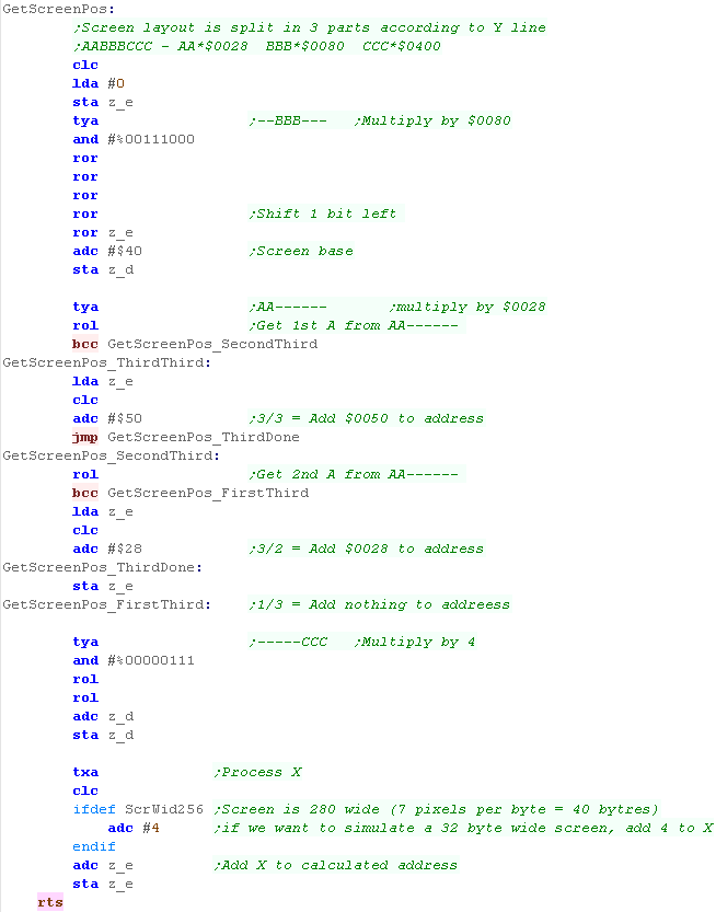
| Memory addresses for Screen Mode
2 is split into 3 chunks,also, every 8 lines we effectively
'reset' our high memory address and add $80 Pixels in Each line are in normal Left->Right format, however remeber 7 pixels are defined by each byte, with 1 bit defining the color palette. We can calculate the address of the start of a line by splitting the bits of the Y line number... On the Apple II the graphics screen can start at $2000 or $4000 ... we'll put it at $4000 so it's out the way of our program code! |
YPOS:
Address= Base+ (AA*$0028) + (BBB*$0080) + (CC*$0400) + XPOS
|
Initializing the screen
| We need to 'set' a variety of
ports to enable the screen in the mode we need... We just need to read or write to or from ports $C050,$C052,$C055 and $C057 to set up the screen mode we need... Just accessing the ports has the effect of setting up the hardware! |
|
|||||||||||||||||||||||||||
| To init the screen, we just need to INIT the screen, displaying Fullscreen graphics... setting HighRes mode, and Setting Page2 - so the screen memory is $4000-$5FFF | 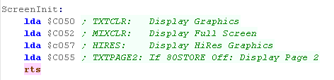 |
| It seems any
data written to, or read from these ports will lave the effect
of causing the setting change... we're using LDA here, but STA will work too, and any value can be written, and the effect will be the same... weird eh? |
|
GetScreenPos to select memory location by XY co-ordinate
| When we want to draw on the
screen, we'll need to calculate the correct memory position to
write the data to... We'll do this with 'GetScreenPos'... it'll use the X and Y regster to specify a co-ordinate, and calculates the equivalent memory location in the zeropage pair defined by z_de We split up the Y-pos, and multiply each part according to the foruma below... YPOS:
Address= Base+ (AA*$0028) + (BBB*$0080) + (CC*$0400) + XPOS |
 |
||||||||||||||||
| Within an 8 line 'block'... We can move down a line by just adding $0400... but we'll have to recalculate the X,Y co-ordinate after that. | 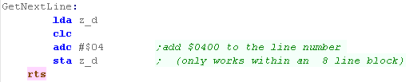 |
Drawing a bitmap to the screen
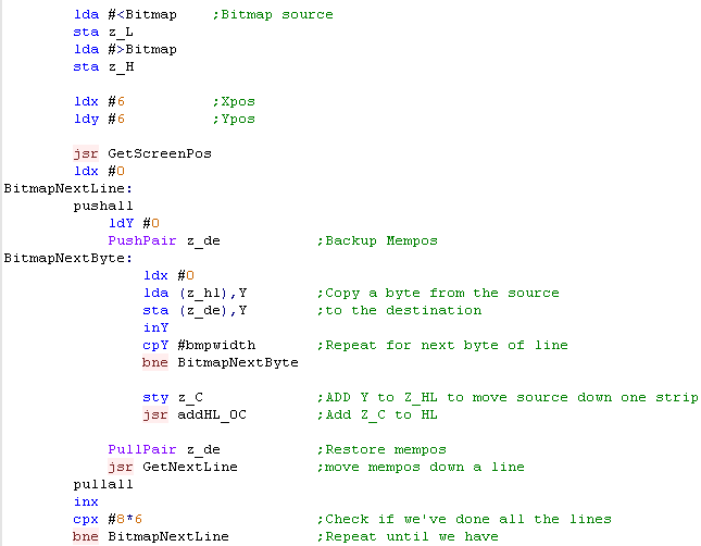
| When it comes to drawing the
bitmap to the screen, we just need to use GetScreenPos to
calculate the destination in z_de... Then we copy lines of data from the source bitmap in z_hl... For the first 8 lines, we can use GetNextLine to calculate the next screen position, but after that we need to call GetScreenPos again to recalculate the new position
|
 |

Lynx Graphics
| The 160x102 video display is created by 8k of normal memory,
and we can just write data into it to set pixels... This is no different to a machine like the BBC - but what is quite odd is the Hardware Sprites of the Lynx... a normal hardware sprite system would be in a separate layer which is drawn, but on the Lynx that's not the case... The Lynx's hardware sprite processor (Suzy) reads compressed sprite data from normal CPU ram, and renders the sprite data back into normal CPU ram!... the sprite CPU is EXTREMELY fast - so this is pretty much instant - and means the Lynx is capable of quickly drawing a HUGE number of hardware sprites! We're not going to use sprites today, but it's important to understand that the Lynx screen is 100% bitmap based! |
 |
Graphics Hardware Settings
| We're going to use a variety of
hardware addresses to set up the screen... though most are
actually for sprite settings... One VERY important thing is that when setting 16 bit HL pairs, we MUST set the Low value first... as writing to the Low value will reset the High value |
|
Setting up Screen Memory
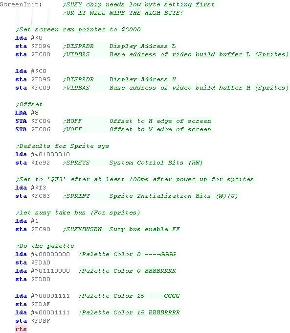
| The lynx uses 8160 bytes of ram,
and the screen memory can be positioned anywhere within
the address space... in fact we would often want two 8k screen
buffers - one visible, and one being drawn In these examples we'll just use one , so we'll draw straight to the visible screen... We also set up the screen 'offsets' - these are used for sprite 'clipping' (where sprites are partially offscreen, and we'll need them later!.... at the same time we'll set up a few other sprite defaults, though we don't really need them today, Finally we'll set up some default colors so we can see our screen and text. |
 |
|
We're loading the screen-buffer at $C000 - near the top of the memory map - but you can load it anywhere you want - also remember, despite the confusion of hardware sprites, we can treat the Lynx screen as a simple bitmap... Grime 6502 did this - it never used hardware sprites - and in fact, for a 6502 the Lynx is very fast anyway - so you may never need hardware sprites! |
Calculating memory position by X,Y pos
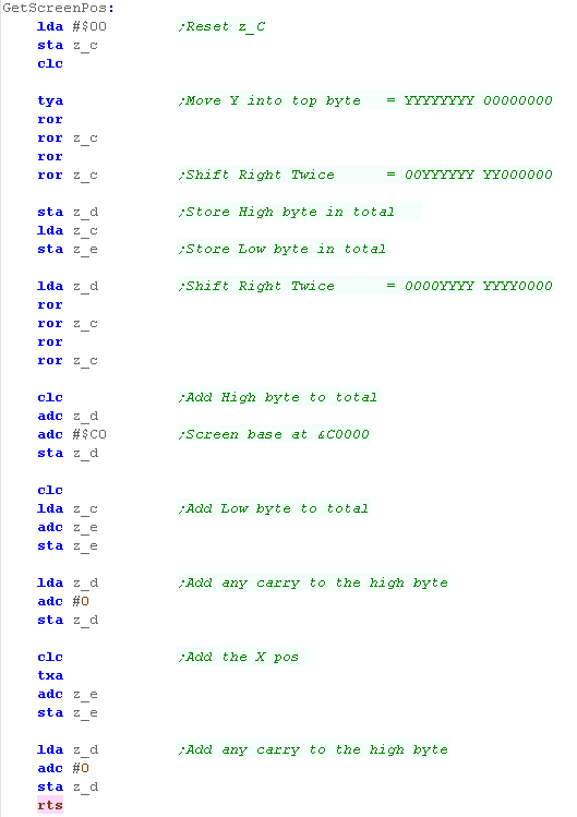
| Each line in the screen is 80
bytes, so to calculate a screen pos we just multiply Y*80 and
add X to get our offset from the base... To effect the multiplication, we'll shift the Y value into the two positions that make up 80 in binary, and add the values to the resulting address |
|
||||||||||||||||||||||||||||||||||||||||||||||||||||||||||||||||||||||||||||||||||||||||||||||||||||||||||||
| This function takes an Xpos in
bytes and, Ypos in lines in the XY registers. When it comes to calculating the address, we use A as the top byte, and z_c as the low one... We load in Y - and shift two bits into z_c... we then store the pair in z_d and z_e Now we shift another two bits... and add to z_d and z_e.... along with the base address of the screen ($C000) Finally we add the X pos, and any carry as required - we've now got the memory address of the required byte in z_de |
 |
||||||||||||||||||||||||||||||||||||||||||||||||||||||||||||||||||||||||||||||||||||||||||||||||||||||||||||
| We can move down a line by just adding 80 to z_de | 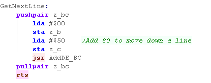 |
Drawing to the screen
| It's easy to draw a bitmap to the
screen, we can just load the bytes from memory (pointed to by
z_hl), get the destination with the GetScreenPos function we
just defined, and then copy bytes to z_de After each line, we need to move down a line, and start drawing again - until all the lines of the bitmap are drawn |
 |
| The bitmap will be drawn onscreen at the position we specify |  |
| Apart from
its' small screen, the Lynx is one of the best systems we'll
be looking at! It has 16 colors - but unlike a tile based
system, we can plot data in memory easily!... Of course if you like the tile based way of doing things, the SNES or PC-Engine may suit you better... Though technically they aren't 6502 based. |
|

The PC-Engine Graphics system
| The PC Engine graphics hardware has 64k of ram... but it's
designed for 128k... it's controlled by a set of registers... we
have 3 hardware ports we use to control the hardware... these
are usually memory mapped to $0000 ... but we also have special
commands to quickly write fixed values to the graphics system We ALWAYS write data to the graphics system registers in HL byte pairs... Little Endian, so low byte first. To write data to the memory we set the address we want to write to with MAWR... but please note , we're only setting the last 16 of the 17 bits... for example, if we set MAWR to $3FFF (%11111111111111), the actual memory address will be %111111111111110 The effect is, that there are 2 bytes at VRAM $0000... and two bytes at VRAM $0001 ... and these bytes DO NOT OVERLAP! |
|
|
The PC Engine
documentation will often show writes to the video hardware at
$0000,$0002 and $0003 - but VASM will confuse these with Zero
page addressing, so we'll write to $0100,$0102 and $0103
instead The ports repeat every 4 bytes, so this has the same effect, and gets around the limitation of the assembler. |
Graphics Registers
There are a variety of Graphics registers, but at this time the main ones we'll need are 0 (Select WRITE) and 2 (Data), these will allow us to write data to the Vram
| Reg | Name | Meaning | Bits |
| 00 | MAWR | Memory Address Write | |
| 01 | MARR | Memory Address Read | |
| 02 | VRR/VWR | Vram Data Write / Vram Data Read | |
| 03 | |||
| 04 | |||
| 05 | CR | Control | - - - IW IW DR TE TE BB SB EX EX IE IE IE IE (BB= Background on) (SB=Sprites on) |
| 06 | RCR | Scanning Line Detection | |
| 07 | BXR | BGX Scroll | ------XX
XXXXXXXX |
| 08 | BYR | BGY Scroll | -------Y YYYYYYYY |
| 09 | MWR | Memory Access Width | - - - - - - - - CM SCR SCR SCR SM SM WV WV |
| 0A | HSR | Horizontal Sync | |
| 0B | HDR | Horizontal Display | |
| 0C | VPR | Vertical Sync | |
| 0D | BDW | Vertical Display | |
| 0E | BCR | Vertical Display End Position | |
| 0F | DCR | Block Transfer Control | |
| 10 | SOUR | Block Transfer Source Address | |
| 11 | DESR | Block Transfer Destination Address | |
| 12 | LENR | Block Transfer Length | |
| 13 | SATB | VRAM-SATB Block Transfer Source |
Vram Layout
| Memory in the Vram is not entirely fixed in purpose, this
means you can have weird effects, like using the same memory
area for your Tilemaps - and tile definitions (Patterns)... this
is totally useless, as one will corrupt the other, but we have to understand it's possible to understand the memory... as stated before, each address has 2 bytes... A Pattern (tile definition) is 32 bytes in size (4 bitplanes, 8 lines)... and because each memory address in the Vram map contains 2 bytes... the pattern will take up 16 memory addresses... this means tile 0 starts at $0000... and tile 1 is at $0010 NOW... the TileMap has to be at $0000 .. and it takes AT LEAST $0400 (it's minimum size is 32x32, and each definition takes 2 bytes)... for ease, it's probably easiest to start your pattern definitions at no 256 (memory address $1000) |
|
Initializing the Screen
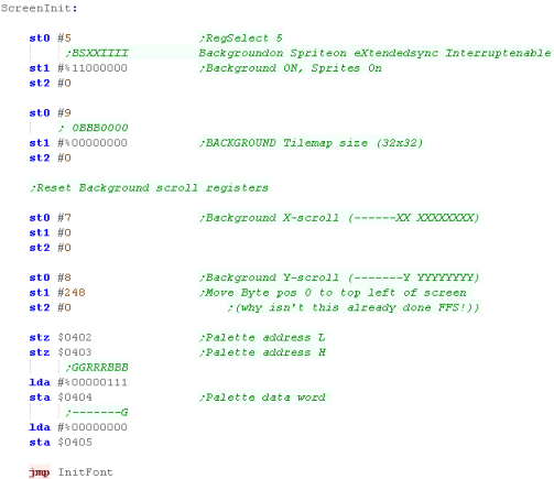
| To start the screen we need to
access Register 5 (the control register) we do this by using ST0
with the parameter #5 We need to turn on the background tilemap with Bit 7, we'll also turn on sprites with Bit 6 (We'll need them later)... we write this using ST1 - we also use ST2 #0, as the registers take 2 bytes Next we need to define our tilemap with Reg 9... we're going to define a 32x32 tilemap for our background. We need to initialize the position of the tilemap with registers 7 & 8... for some reason 0,0 will not be the top corner unless we set the Ypos to 248! Last we'll set the background color to blue by setting entry 0 in the VCE to a blue color... By default all the colors are white, and we wouldn't be able to see anything! |
 |
| We're
setting up a scrolling area of 32x32, but the visible screen
is 32x29 - if we were making a game with a scrolling
background, it would make sense to have a scrolling area of
64x32 or more, It just depends what you're doing, Grime 6502 has no scrolling, so this layout was fine! |
|
Drawing our bitmap
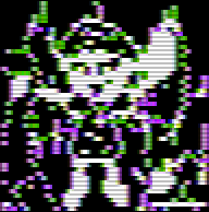
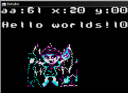
| We're going to draw our 'Chibiko'
character to the screen... the character bitmap is 48x48 , we're
going to have to split it into 8x8 tiles to get it onto our
screen... The tiles are defined in Vram from $1000-$7FFF - this range will have tile numbers 256+ , but the first few will be used by our font, so we'll start at tile 384 (256+192) |
 |
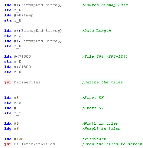
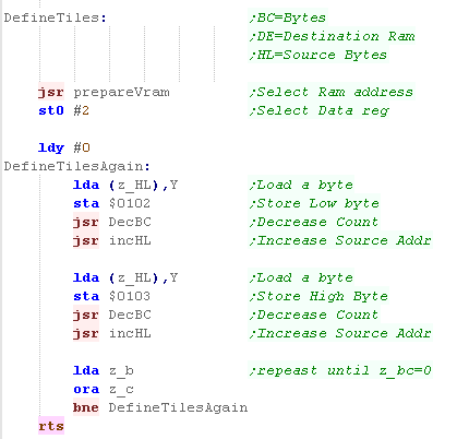
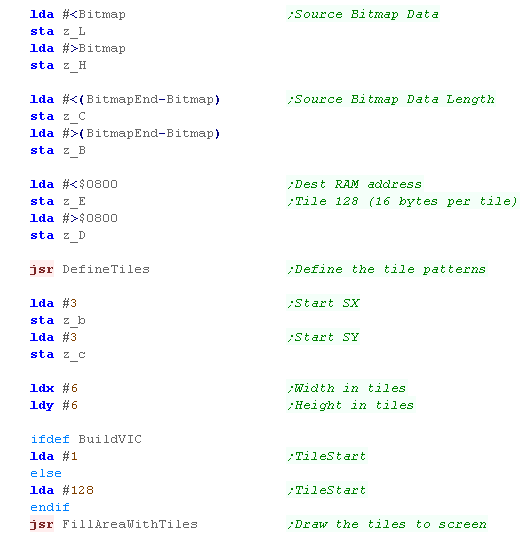
| We're going to use the function
DefineTiles to transfer the bitmap data to Vram... the source
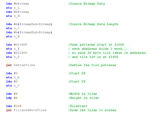
will be defined by zeropage addresses defined as z_H and z_L The Bytecount will be defined by z_B and z_C the destination memory address will be defined by z_DE.... each tile is 32 bytes, and we're going to write to tile 256+128 (384)... so we'll be writing to memory address $1800 Once our tiles are defined, we going to draw them to the screen with the FillAreaWithTiles command... this takes an X and Y pos in z_B and z_C We also need a width and height - which we'll store in X and Y... We'll load the first tile as 128 into A - though the function will add 256 automatically (for compatibility with systems other than the PCE) |
 |
VRAM functions
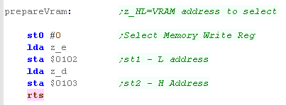
| Our PrepareVram
function will send the address in z_HL to the address
select register at $0102 (ST1) and $0103 (ST2) - this will
prepare Vram to Write (or read) data |
 |
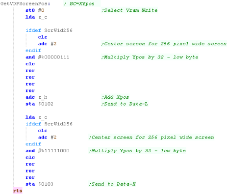
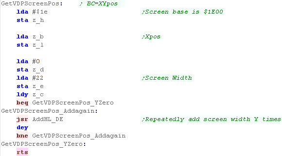
| We're going to create a function
called GetVDPScreenPos - this will convert an XY co-ordinate in
z_b and z_c into a memory address - effectively setting the VRAM
write location for the selected tile number We do this by multiplying our Ypos by 32 (the width of each line in tiles) and adding the Xpos. We have to split the Ypos calculation into two parts, as part of this needs to be passed in the High byte, Finally, we have an extra option called ScrWid256 - this will center the screen to simulate a 256x192 screen (used for Grime 68000) |
 |
|
Remember, We're using $0102 and $0103 to write data - you may see elsewhere $0002 an $0003 used for the same purpose, but this confuses VASM - as it mistakes them for the zero page... But whatever you use the result is the same, as the ports repeat every four bytes! |
Getting Tiles to the screen
| Our DefineTiles function will use
the PrepareVram function to get the memory ready to receive
data. We'll then stream the bytes to vram via Register 2.... we have to write in pairs, as the Vram works in Words... We keep repeating the process until z_bc reaches zero |
 |
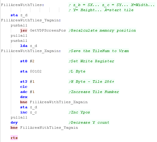
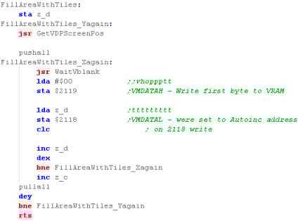
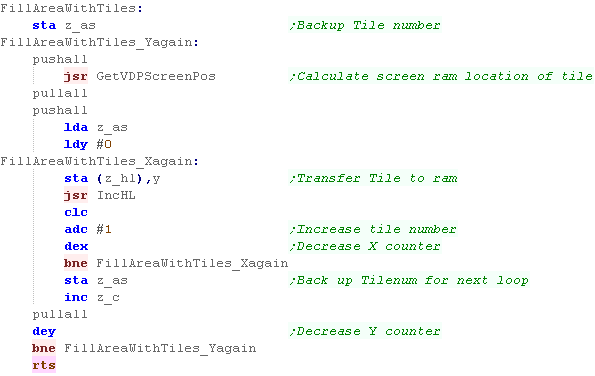
| Now we've defined our tiles, it's
time to set the Tilemap to show them, we do this with
FillAreaWithTiles... This will use the GetVDPScreenPos function to calculate a memory address, and then we'll write tile numbers to the vram - into the tilemap.... note, the high byte is 1 - as all tile numbers on the PcEngine have 256 added to them We loop until we get to the end of the line, then we repeat - recalculating our VDPScreenPos until we've done all the lines. By the end of this procedure, our character will be drawn to the screen! |
 |
| We've seen how to use tiles to get
graphics on the screen, we do the same for the font, we've
just defined the first 128 characters as our letters, and we
set parts of the tilemap as needed... We can do the same to make a simple game, see Grime 6502... if you want to do better graphics, you want to use sprites, we'll look at those later! |
|
Tilemap Definitions
| As with everything else on the PC engine Vram... each tile
definiton takes one memory address, which contains 2 bytes... The top 4 bits pppp define a 16 color palette number from 0-15... The remaining 12 bits nnnn nnnnnnnn define the tile number - as stated, the first 64-256 probably can't be used because they overlap the tilemap... no's 2048-4095 CANNOT be used, as the memory these would use would be 64k-128k... and this memory is not installed in the PC Engine. |
ppppnnnn nnnnnnnn |
| If you use
AkuSprite Editor (included in the Sources.7z) you won't need
to worry about the data format of the tiles - as it's a
little odd! But if you do, then you'll need to know about the format, shown below! |
|
Tile definitions use 4 bitplanes for 16 colors, and tile definitions are 8x8 - so 32 bytes ... Data is transfered in Words, and rather strangely we send bitplane 1+2 of lines, one at a time... then we do the same for bitplanes 3 and 4
| Byte 1 | Byte 2 | |
| First 16 bytes | 00111100 01111111 01100011 01100011 01111111 01100011 01100011 00000000 |
00222200 02222222 02200022 02200022 02222222 02200022 02200022 00000000 |
| Second 16 bytes | 00333300 03333333 03300033 03300033 03333333 03300033 03300033 00000000 |
00444400 04444444 04400044 04400044 04444444 04400044 04400044 00000000 |

The NES/Famicom Graphics Hardware
The NES has dedicated VRAM which contains tile patterns and the Tilemap... We'll need the patterns for our font and the bitmap definitions, and set these in the TileMap to see them onscreen.
By default the NES has just 2k of VRAM, and tile definitions are in ROM, but we'll use 'Memory Mapper 4' - a cartridge based upgrade - this increases VRAM up to 8k, and allows us to define patterns in RAM like on other systems!
On an emulator, we just define the mapper we need in the cartridge header...
When it comes to using VRAM, and the graphics hardware in general we use the PPU ports...
PPU (Nes graphics hardware) Graphics ports
| The PPU is the NES and
Famicom's Graphics system, it's controlled by 8 registers
between $2000 and $2007... we use these to check and set
attributes of the system. and write to VRAM (which isn't in
the normal memory map!) Some of these ports take two bytes - both should be written consecutively to the same port... Strangely, when we want to write to VRAM, it's in Big Endian mode - so we have to send the High byte, then the Low byte... the opposite of the normal 6502! |
| Port | Name | Bits | Details | Notes |
| $2000 | PPUCTRL | N-SBPIAA | N=NMI
on
vblank S=Sprite size B=Back Pattern Table P=sprite Pattern table I=Increment vram address AA=Name Table address |
I=0 means +1 , I=1 means +32 |
| $2001 | PPUMASK | CCCBSsbM | CCC=Color
emphasis B=Background on S=Sprite on s=sprite clip b=back clip M=monochrome |
s= 0 - hides leftmost 8 pixels b= 0 - hides leftmost 8 pixels |
| $2002 | PPUSTATUS | Read resets PPUSCROLL | ||
| $2003 | OAMADDR | Sprite address | (0-255) | |
| $2004 | OAMDATA | Sprite data (to write to addr, autoincs) | ||
| $2005 | PPUSCROLL | XXXXXXXX YYYYYYYYY | Select X offset and Y Offset | |
| $2006 | PPUADDR | HHHHHHHH LLLLLLLL | Select Address to write to (Big Endian!) | Write resets PPUSCROLL |
| $2007 | PPUDATA | BBBBBBBB | Byte to write to address in $2006 |
Vram Layout
| Specify a memory address by writing the byte pair to
$2006... HIGH BYTE FIRST... (Big Endian) NOTE: Writing to VRAM outside of VBLANK will cause problems... also note, selecting an address resets PPUSCROLL EG, lets point to $3F00... and write $11 to the first palette entry! lda #$3F ;High byte sta $2006 ;Send to vram select lda #$00 ;Low byte sta $2006 ;Send to vram select lda #$11 ;New value sta $2007 ;Send to write data |
|
Pattern Definitions for sprites and tiles
The NES has 2 pattern tables, they are selected with PPU Register $2000 Bit 4 & 3
Basic NES roms have pattern definitions in ROM (CHR-ROM), but we can use a mapper with extra video ram to make things easier - in these tutorials we'll use Mapper 2 - so we don't have to worry about CHR-ROM and can change the patterns whenever we like!
The Famicom uses bitplanes for it's data - 2 bitplanes for 4 colors... this means a tile uses 16 bytes
First we send all 8 lines of the first bitplane, Next we send all 8 lines of the second bitplane.
| Byte Data | |
| First 8 bytes | 00111100 01111111 01100011 01100011 01111111 01100011 01100011 00000000 |
| Second 8 bytes | 00222200 02222222 02200022 02200022 02222222 02200022 02200022 00000000 |
|
You shouldn't need to
worry about the tile format if you use AkuSprite Editor - the
open source sprite editor supplied with these tutorials will
do the work for you. The NES 'Save Raw bitmap' option was used to convert the sample bitmap into a grid of tiles in the correct format for the NES! |
Turning On the screen
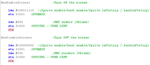
| We need to turn on the screen
before we can see anything, we do this with port $2001... we
also need to turn on our VBLANK interrupts with the PPUCTRL The NES graphics system has an annoying limitation! Whenever we write data to the VDP it will mess up the display scroll position, so there may be times we need to turn the screen off - as a way of solving the problem, we do this by clearing the same two ports |
 |
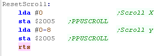
| As writing to the PPU will mess
up the scroll position, we'll define a function to reset it. This sets the correct values to position the tilemap, so the byte at VRAM address $2000 is the top left of the tile map |
 |
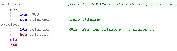
| We can't write to VRAM outside
of VBLANK (The time the screen is not being drawn)... because
of this we're going to need a function to wait for VBLANK to
restart. We do this by checking a zero page entry 'Vblanked' - and waiting for it to change... our interrupt handler will change this value when the interrupt occurs We'll see an interrupt handler later in the lesson! |
 |
|
Every time we write to the screen, we
need first wait for VBLANK (when the screen isn't being
drawn) and also reset our scroll after we're done. This is a real pain, but we'll learn a trick to work around it! |
Getting our character to the screen (Via the tilemap)
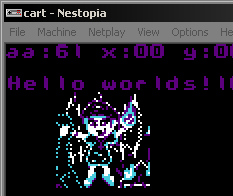
| We're going to show our Chibiko
character to the screen! The bitmap is 48x48 - and so as our tiles are 8x8, we'll be splitting it up into a grid of 6x6 tiles (36 tiles) We'll use two commands to do this, one will send our bitmap data to the VDP defining the Tile patterns, the other will set the Tilemap to show those patterns to the screen |
 |
| The code we'll be using to get
the bitmap to the screen is the same as on the PC engine...
the only difference is the destination address of the data... As the first 128 tile patterns are used by our font, we'll be using tiles 128+... as NES tiles are 2bit per pixel (4 color) each 8x8 tile is 16 bytes... so tile 128 is at memory address $0800... we load this into z_de zero page addresses We load the source bitmap into z_hl and the size of the bitmap in z_bc the DefineTiles function will copy the data into the VRAM Once the tiles are defined, we set the XY pos to draw to in z_bc, and the WIDTH/HEIGHT in the X/Y registers... we also set the first tile in register A , then we call FillAreaWithTiles to draw the bitmap to screen |
 |
Defining Tiles
| We're going to define our
Chibiko character... Sending data to VRAM will mess up the screen, so we'll first turn off the screen, We'll then use the PrepareVRAM command to select the destination address Once that's done, all we need to do is send each of the bytes of our character to address $2007 (PPUDATA) After all the data is sent, we turn the screen back on! |
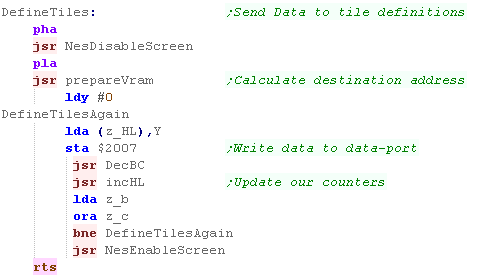 |
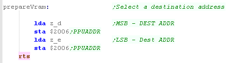
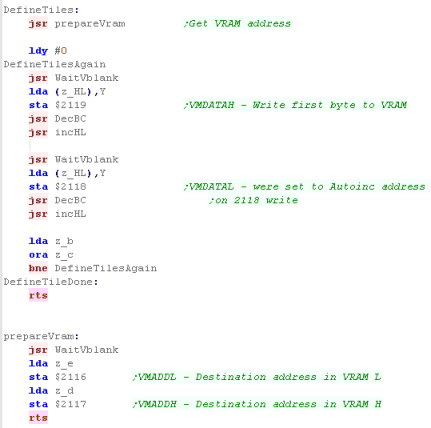
| The Prepare VRAM command is
also very simple, to select the memory address in zero page
entries z_de, we just write the high byte z_d to address $2006
(PPU ADDR), then the low byte z_e to the same address.. This sets the address the data will be written! |
 |
Showing the tiles
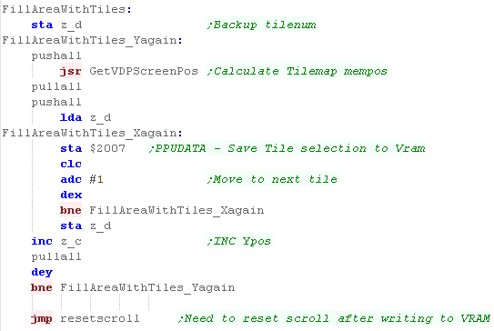
| As we saw before,
FillAreaWithTiles will set the visible tiles to a range of
defined patterns. The first tilenumber is in A, the width is in X, the height is in Y, and the start XY pos is in z_bc We use GetVDPScreenPos to select the correct position in the tilemap, then we write our tile number into VRAM to show that tile in the selected position... VRAM auto-increments, so we can just write consecutive tile numbers until we get to the end of the line, once we 've completed a line, we jump back and re-run GetVDPScreenPos Writing to VRAM messses up the scroll position - so we reset it once we're done... there is a way to avoid this, which we'll learn in a moment! |
 |
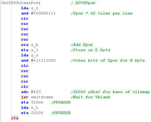
| Calculating the VRAM position
is not hard, as the tilemap is 32 wide, we multiply the Y pos
by 32, add the X pos and the base of the tilemap ($2000)... We do the multiplication by bit-shifting. Once we've calculated the address, we need to wait for VBLANK - as we can't write to VRAM at any other time Then we send it the PPUADDR.... high byte then low byte! |
 |
| The Code above
works for an example, but it's useless in games, as we keep
having to wait for VBLANK before each write, and reset our
scroll afterwards... We need to get smarter! we're going to store up all those writes, and send them in VBLANK while the screen isn't being drawn... The result will be no waiting around, and no visual corruption caused by the scroll changing! |
|
Using a buffer to stop the scroll problem!
The PPU messes up our scroll whenever we write, and we can only write in VBLANK, and waiting for it is slow... what we need is to store what we want to write in a buffer, then send all that data during VBLANK...
We'll do this below, we'll store up to 32 changes we want to make to VRAM, each will contain 3 bytes.. a HL address pair and a new value to write
| Here is our 'new and improved'
GetVDPScreenPos command... It's mostly the same, but the last part has changed We're now using the function 'Get VDPBufferCT'... this will check the buffer isn't full, and return the position that we can write our new data into in the Y register... The function writes the new destination address into the buffer VDPBuffer, leaving us to write the last one ourselves |
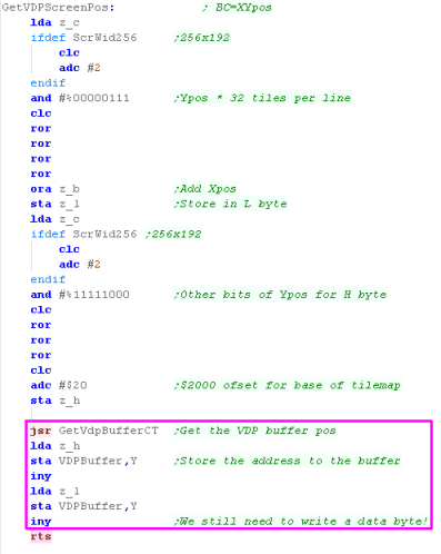 |
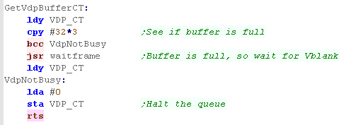
| The GetVDPBufferCT function will
read the buffer position from the zero page entry VDP_CT... if
the buffer is full it will wait for VBLANK, When the buffer is not full, it will return Y pointing to the next entry... but it will temporarily set the buffer size to Zero, so if an interrupt fires, it doesn't process an incomplete queue |
 |
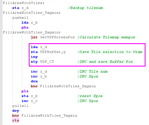
| Our FillAreaWithTiles has also
changed... We now need to call GetVDPScreenpos for every byte, as we need one address header in our buffer per written byte... Then we update our buffer... We then write our new byte, and save the new buffer count in zeropage VDP_CT |
 |
The
Interrupt
handler
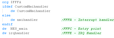
| We define the address of our
interrupt handler at the top of the memory map, at $FFFA We need to point to the address of our interrupt handler, that will handle the Vblank |
 |
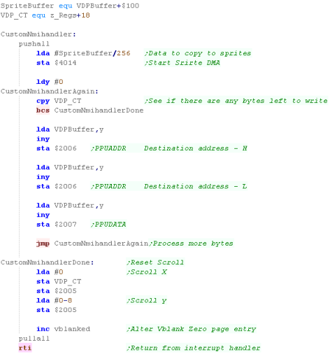
| Here's our Interrupt handler that
will run during VBLANK. First we're starting the Sprite DMA with $4014... don't worry about this - it's for a later lesson! Next we load in the waiting command count from VDP_CT... For each waiting command, we write the HL address to $2006, and the new byte value for that address to $2007 We repeat until all the bytes are done Once all the bytes are written, we zero the buffer count in VDP_CT, As we've written to VRAM, we need to reset the scroll position as before. |
 |
|
This buffer
code works, but it's pretty basic and crappy! A better one may support RLE - where lots of bytes are all filled with the same value, This code also wastes a lot of buffer bytes - as each written byte has an address pair... if all the bytes are consecutive, this is very wasteful! |

PPU Ports for Graphics
The Snes has a large number
of ports for Graphics, but we won't need many today! here's the most
important ones...you can see the full list here
These are all memory mapped, so we can just write to these addresses in the 64k address space (in 6502 mode)
These are all memory mapped, so we can just write to these addresses in the 64k address space (in 6502 mode)
| rw | Address | Name | Purpose | Bits | Details |
| w | $2100 | INIDISP | Screen display | x000bbbb | x=screen disable (1=disable) bbbb=brightness (15=max) |
| w | $2101 | OBSEL | OAM size (Sprite) | sssnnbbb | sss^size nn=name addr bb=base addr |
| w 2 | $2102 | OAMADDL/H | OAM address | aaaaaaaa r000000m | a=oam address r=priority m=addr MSB |
| wd | $2104 | OAMDATA | OAM data | ???????? ???????? | |
| w | $2105 | BGMODE | Screen mode | abcdefff | abcd=tile sizes e=pri fff=mode def |
| w | $2107 | BG1SC | BG1 Tilemap VRAM location | xxxxxxab | xxx=address ab SC size 00=32x32 01=64x32 10=32x64 11=64x64 |
| w | $210B | BG12NBA | BG1 & BG2 VRAM location | aaaabbbb | aaa=base addr for BG2 bbb=base addr for BG1 |
| wd | $210D | BG1HOFS | BG1 horizontal scroll | mmmmmaaa aaaaaaaa | aaa=horiz offset, mmm=Mode 7 option |
| wd | $210E | BG1VOFS | BG1 vertical scroll |
|
|
| w | $2115 | VMAIN | Video port contro l | i000abcd | I 1=inc on $2118 or $2139 0=$2119 or $213A� abcd=move size |
| w 2 | $2116-$2117 | VMADDL/H | Video port address | LLLLLLLL HHHHHHHH | Memory address (in bytepairs?$0000-$7FFF |
| w 2 | $2118-$2119 | VMDATAL/H | Video port data | LLLLLLLL HHHHHHHH | Byte Data |
| w | $2121 | CGADD | Colour # (or pallete) selection | xxxxxxxx | x=color (0-255) |
| wd | $2122 | CGDATA | Colour data | -bbbbbgg gggrrrrr | Color Data BGR |
| w | $212C | TM | Main screen designation | ---S4321 | S=sprites 4-1=enable Bgx |
VRAM
What the VRAM addresses do is reconfigurable, we can change the position of the tilemap in RAM, Here's a sample map which we'll be working around in these tutorials ... Note the addresses are in WORDS (2 bytes in each address)... so the 64k memory is accessed by addresses $0000-$7FFF
What the VRAM addresses do is reconfigurable, we can change the position of the tilemap in RAM, Here's a sample map which we'll be working around in these tutorials ... Note the addresses are in WORDS (2 bytes in each address)... so the 64k memory is accessed by addresses $0000-$7FFF
| Address | Use |
| $0000 | BG1 Tilemap |
| $1000 | Tile Patterns |
| $4000 | Sprite Patterns |
| $7FFF | Last byte of ram |
Tilemap Data
The Tilemap will typically start from address $0000, each entry contains two bytes
The Tilemap will typically start from address $0000, each entry contains two bytes
| F | E | D | C | B | A | 9 | 8 | |
7 | 6 | 5 | 4 | 3 | 2 | 1 | 0 | |
|
| V | H | L | P | P | P | T | T | T | T | T | T | T | T | T | T | V=vflip H=hflip L=layer (in front of sprites) P=palette T=tile number |
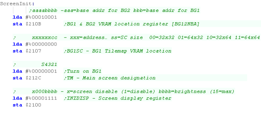
Screen INIT
| We're going to initilize the
screen, first we need to set the position of our
background tilemap... we're using the settings shown above, with
BG1 at $0000 we're also setting the tilemap size - we're using a 32x32 tilemap in these examples. |
 |
| We need to turn on the layer (we're using layer 1), we'll also set the screen brightness! | 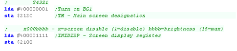 |
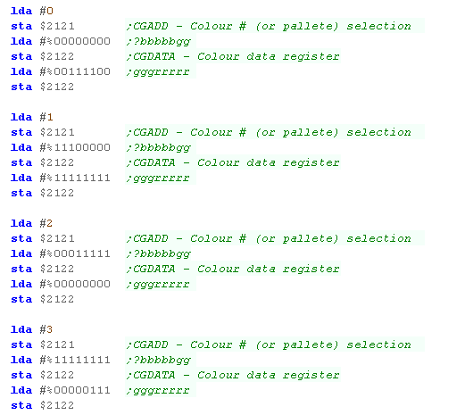
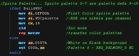
| We're going to set up a basic
palette, with blue as the background color, and the first 4
colors set... To set a color, we write the palette inxex to $2121 Then we write 2 bytes of the color definition to $2122 |
 |
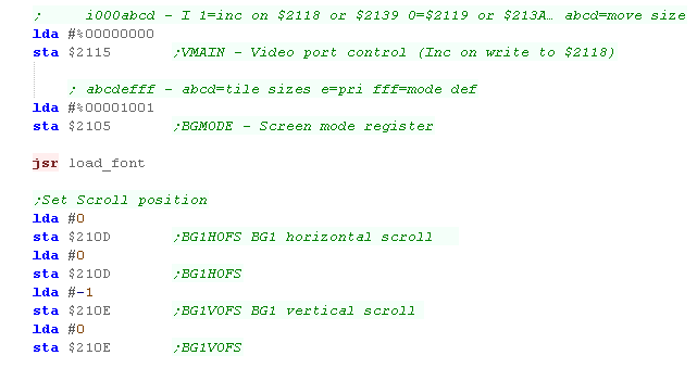
| We need to do something quite
important next... when we write data to the ports $2118 and
$2119... depending on this setting we'll inc on the High byte,
or Low byte being written... we're going to set it up to update
on $2118 - the low byte Now we're going to set up the screen mode, load the font, and finally set up the scroll position We're going to set the scroll so that the top left of the screen shows the first tile in the tilemap Finally our screen is set up! |
 |
Waiting for Vblank
Getting our bitmap on the screen
Defining Tiles
Showing the tiles to the screen
Using DMA to create a buffer... and send it in VBLANK
The code above mostly works, but waiting for vblank before each write slows things down (although not much, as the SNES is super fast)... but it also caused noticable glitches in Grime 6502... what we should do is create a buffer of the tilemap, and copy it with a DMA during the interrupt!
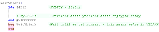
| We can't write to the VRAM while the screen is being drawn,
as it will cause problems... so we need to wait for VBLANK... Vblank is where the screen has been drawn completely, but redraw has not restarted yet.... We can detect this by tesing bit 7 of $4212... we'll be using this command a lot! |
 |
|
While we have to wait for VBLANK on the
snes, unlike the NES we don't have to reset the scroll
position... Like the NES, we're going to learn a better way of doing things later in the lesson! |
Getting our bitmap on the screen
| The code is the same as the
NES/PCE We uise z_hl as our source data, z_bc as the size of the data, and z_de as the destination in VRAM. Our tiles are 16 color 4bpp... so we'd expect our 8x8 tiles to take address entries... but they only take 16! You see, on the SNES, each address holds a word - two bytes... so we're going to write our data to $1800... $1000 (the pattern base) + $800 (128x16) We'll then use DefineTiles to transfer the data to VRAM Once we've defined the tile patterns, we need to get them to the screen... we load the XY pos to draw to into z_bc and call DefineTiles... this will draw our bitmap onto the screen |
 |
| You can see our character drawn to the screen! | 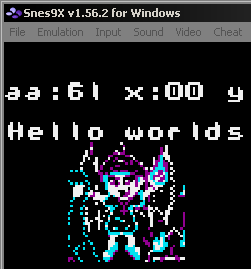 |
|
You can
create SNES format tiles with Akusprite Editor... in fact
AkuSprite editor can make graphics for EVERY SYSTEM IN THE
ENTIRE WORLD!!! OK, that's a total lie... but it can do every system covered in these tutorials... and that's quite impressive isnt it? |
Defining Tiles
| As we just saw the DefineTiles
function transfers z_bc bytes of data from z_hl in ram to z_de
in VRAM To set up the destination address we use prepareVRAM, this will select the memory address we want to write to, by sending the HL address of the VRAM to write to $2116 and $2117 BUT... before we can write to these ports we need to be sure we're in VBLANK, so we call WaitVBlank, which will pause untill we are! We can now transfer from z_hl to the PPU We now write our byte pairs to $2119 and $2118... we've set up our PPU to auto-increment the destination address whenever we write to $2118... remember each address in VRAM takes 2 bytes (a word) We loop until we've transferred all the data bytes in z_bc |
 |
Showing the tiles to the screen
| We're now going to set the
tiles in the tilemap to show tile patterns we just defined in
a grid! We're going to use a command 'GetVDPScreenPos' to covert an XY position into a memory location in the tilemap Once again, we need to wait for VBLANK, before we write our data... .once we're in Vblank, we can write our tile numbers... each takes two bytes, but we'll be writing the top byte as #0 (limiting us to 256 tiles) We can just keep wriing tiles until we get to the end of the horizontal line, then we recalculate the memory position at the start of the next line. We repeat until the area is filled. |
 |
| Waiting
for Vblank every time isn't as bad on the SNES as it was on
the NES due to the speed of the system, ... but it's not
really good enough either - there were some graphical
glitches on Grime 6502 on the SNES... so once again we're
going to buffer the data, and send it in VBLANK.... But the SNES makes it easier for us, as we have a DMA which will do a big copy for us during VBLANK! |
|
Using DMA to create a buffer... and send it in VBLANK
The code above mostly works, but waiting for vblank before each write slows things down (although not much, as the SNES is super fast)... but it also caused noticable glitches in Grime 6502... what we should do is create a buffer of the tilemap, and copy it with a DMA during the interrupt!
| rw | Address | Name | Purpose | Bits | Details |
| w | $4200 | NMITIMEN | Counter enable | a0yx000b | |
| w | $4201 | WRIO | Programmable I/O port (out-port) | ||
| w | $4202 | WRMPYA | Multiplicand 'A' | ||
| w | $4203 | WRMPYB | Multiplier 'B� | ||
| w 2 | $4204 | WRDIVL/H | Dividend C | ||
| w | $4205 | WRDIVB | Divisor B | ||
| w 2 | $4207 | HTIMEL/H | Video H IRQ beam pos/pointer | 0000000x xxxxxxxx | x: Beam position. |
| w 2 | $4209 | VTIMEL/H | Video V IRQ beam pos/pointer | 0000000y yyyyyyyy | y: Beam position. |
| w | $420B | MDMAEN | DMA enable | 76543210 | |
| w | $420C | HDMAEN | HDMA enable . | ||
| w | $420D | MEMSEL | Cycle speed | 0000000x | 0=2.68 1=3.58 |
| r | $4210 | RDNMI | NMI | x000vvvv | x=disable NMI v=version |
| rw | $4211 | TIMEUP | Video IRQ | i0000000 | i=irq enabled |
| rw | $4212 | HVBJOY | Status | xy00000a | x=vblank state y=hblank state a=joypad ready |
| r | $4213 | RDIO | Programmable I/O port (in-port) | ||
| r 2 | $4214 | RDDIVL/H | Quotient of divide result | ||
| r 2 | $4216 | RDMPYL/H | Multiplication or divide result | ||
| w | $43x0 | DMAPX | DMA Control | vh0cbaaa | |
| w | $43x1 | BBADX | DMA Destination | LLLLLLLL | H=$21 |
| w 2 | $43x2 | A1TXL/H | Source address | ||
| w | $43x4 | A1BX | Source bank address | ||
| w 2 | $43x5 | DASXL/H | DMA transfer size & HDMA address | ||
| w | $43xA | NTRLX | Number of lines for HDMA transfer | cxxxxxxx | C=continue (0=yes) x=lines to transfer |
| We're going to use a buffer
this time... this will be held in ram, and cover the entire
2048 bytes of the tilemap from the ram into the VRAM. Even better, we don't need to do this ourselves! We can use the SNES DMA (Direct Memory Access) to copy the data. The DMA command is designed to work with the destination registers $2118 and $2119 for VRAM data, but we're going to need to specify the destination address in Vram ($0000) and configure the AutoInc to update on $2119 (we were updating on $2118) We have to specify the source address as a 24-bit address, because although we're working in 6502 mode, the 65816 is a 24 bit CPU. At the enbd we start the DMA with port $420B... note we turn off something called 'H-DMA' (Horizontal DMA)... we don't need it to copy with VBLANK, but it shares the same settings The DMA will transfer the data... the CPU effectively halts during the transfer, so the job is done before our next command we then turn the AutoInc back to update on $2118, and return from interrupts with RTI |
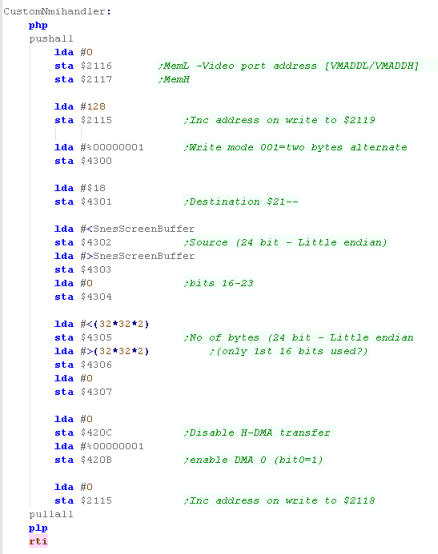 |
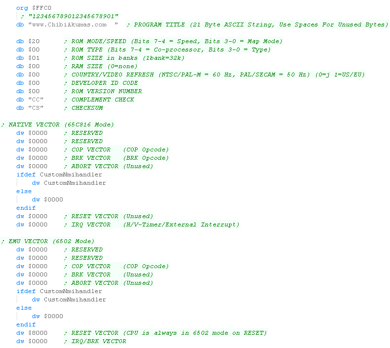
| We need to add pointers to the footer of our ROM file - the
CustomNMIHandler is included in the NMI position... Note there are two versions - one for the 65816 mode, and one for 6502 mode (though our tutorial uses 6502 mode) |
 |
| We need to change our GetVDPScreenPos... we now caclulate the memory position in the SnesScreenBuffer for the address... and store that address into z_hl | 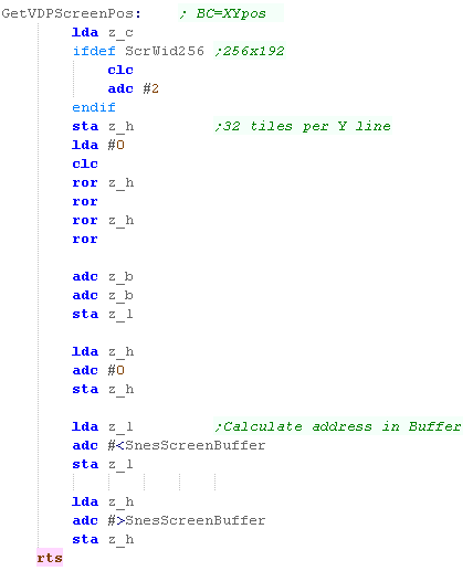 |
| The FillAreaWithTiles function has been changed, it now writes the Tile number into the z_hl address.... this will then be copied into VRAM during the next VBLANK | 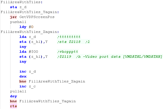 |
|
The SNES code is much
easier thanks to the DMA... on the NES we had to buffer just a
few changes, and send the changes during the VBLANK... Having enough RAM and speed to buffer the whole tilemap is a big help... we're still sending the Tile patterns in the same way, waiting for Vblank, but we'll probably only do that a the start of our game/level anyway. |

The VIC Character Map ... ASCII is for wimps!
| The VIC does
NOT use Ascii... as we don't have enough ram for a custom
font, we're going to have to learn how to convert the
charmap... if we set the Character memory to $1C00 the Ascii set is offset by 128, and the inverted characters are lost... the result is the @ symbol is now character 128, and 0-127 are the custom characters  |
By setting register $9005 we can remap the character map...
here are the options
|
| In these
examples we're going to set the Character memory to $1C00 -
this puts it just below the Screen... this only allows
enough ram for 64 character... we can however move the screen to $1000 - this gives enough for 128! |
|
Setting Up our Screen...
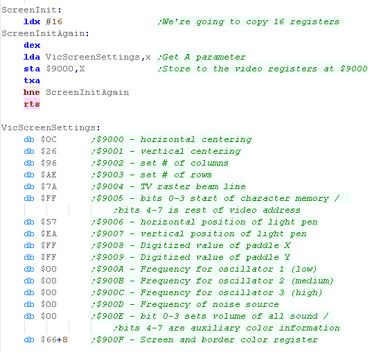
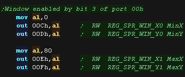
| We're going to need to set up the
screen registers... especially if we're using a VIC cartridge
(where basic doesn't run to set things up for us)... we do this
by copying a bank of settings to $9000-$900 We're going to set up our basic screen, most of this is just the defaults for a 'normal' screen - so we can use this if we're using a ROM cartridge without basic setting things up for us, there are a few 'special' bits though... We're going to set the screen background to blue ($900F) ... not too much exciting there The more important one is ($9005)... bits 0-3 set the base of the character memory... we've set it to F... which means the first 128 characters are defined by the ram at $1C000... the second 128 are what WERE the first 128 - the basic character set |
 |
Drawing our Bitmap
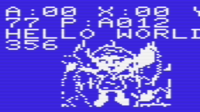
| We're going to get our 48x48
bitmap onscreen by splitting it into 6x6 character blocks,
defining it as a set of custom characters (from 0-35) We then set the screen to those character... Effectively this is the same as the 'tilemap' procedure, but we're calling them characters for now, because that's what the VIC calls them! |
 |
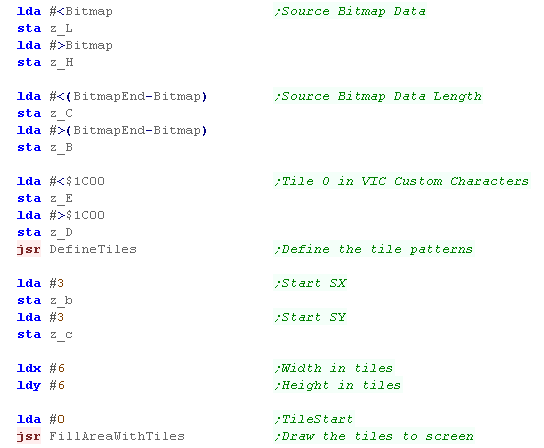
| Because it's more like a tilemap
than a bitmap, we're going to use the same code as on the
PCE/NES etc We're going to define our source data in zero page z_hl... and the length of that data in z_bc we'll also define the destination in ram in z_de.... in this case $1C00 - character 0 of the custom characters Once we've defined the characters, we use 'FillAreaWithTiles'... this puts a 6x6 'grid' of those custom characters onscreen, effectively drawing the chibiko bitmap to screen. |
 |
Defining our tiles
| Defining our tiles is mega
boring... we just copy the source data to the correct location
in ram ($1C00)... of course, if our game is in RAM, we can just
position the characters in memory at that location with an ORG
statement We're not doing things that way in this example, as it allows our code to run from RAM or ROM |
  |
Setting our tiles
Screen Layout on the C64
Graphics Memory and ports
The C64 uses a set of memory mapped registers to control the screen, and various areas of memory are used for the screen bitmap and color data.
Bitmap Graphics
There are two modes for Bitmap graphics on the C64
Normal mode (2 color) is 320x200... it has 2 colors per 8x8 tile, the "Bitmap data" is typically located between $2000-$3FFF, this is a 1 bpp bitmap, each tile will get its background color from the low nibble of $D020, and it:s foreground color from the low nibble of $D800-$DBE7
Multicolor Mode (4 color) is 160x200 , it has 4 colors per 4x8 tile, but setting those colors is more tricky... again it uses a bitmap screen at $2000-$3FFF, but is 2bpp... it uses a 160x200, 2 bits for each pixel choose a color from 1 of 4 locations
The Border Color is defined by $D020
Setting up the screen
Displaying our bitmap
GetScreenPos
Common Data format for Joypad controls used by these tutorials
| Like previous examples, we'll
use FillAreaWithTiles... This will fill the specified area with concecutive character numbers, and allows our bitmap to draw to the screen. We use the command 'GetVDPScreenPos' which will calculate the memory location of a character from the X,Y position in z_b,z_c we then just write a number to the address in z_hl - this will be the character in that location, We repeat the procedure for the rest of the line, then recalcualte the new address for the next line. |
 |
| We're going to use a
'getVDPScreenPos' command to calculate the memory location
from the X,Y character position... The formula is ScreenBase+Ypos*ScreenWidth+Xpos.... The Screen width is 22, the Screen base is $1E00.... so the formula is: $1E00+Ypos*22+Xpos.... In this case, we're simulating a 'multiply' by just repeatedly adding 22 Y times - it's not quite as advanced as other cases where we've done bitshifts and adds, but it works well enough. |
 |

Screen Layout on the C64
| The screen layout on the C64 is
the same as the BBC... The screen is split up into 8 pixel tall strips... and these are stored in memory Y first... then X Lets imagine we write bytes to consecutive memory addresses (displayed as 0-641 in the diagram to the right)... when we write to the first 8 pixels, they go DOWN the screen... but the 9th pixel will go back up to the top of the strip This will continue until the far right of the screen... then the next byte will be the far left of the next 8 pixel tall strip. |
 |
|
The odd screen layout
will make calculating memory addresses tricky later, but it
should make sense if you look at the diagram above... But of course, todays example code should just work fine 'as is' so don't worry about it if you don't understand it! |
Graphics Memory and ports
The C64 uses a set of memory mapped registers to control the screen, and various areas of memory are used for the screen bitmap and color data.
| Address | Description | Bits | Meaning |
| $0400-$07E7 | Default area of screen memory | (1000 bytes). | |
| $2000-$3FFF | BMP Screen Ram | ||
| $D000-$D7FF | Char ROM in uppercase/graphics character set | (2048 bytes, 256 entries) | |
| $D800-$DFFF | Char ROM in lowercase/uppercase character set | (2048 bytes, 256 entries) | |
| $D011 | Screen control register #1. | LXMSHVVV | L=Cur Line X=extended BG M=mode (Txt/Bmp)S=screen on H=height V=Vert scroll |
| $D016 | Screen control register #2 | ---MWHHH | M=Multicolor W=scr width H=horiz scroll |
| $D018 | Memory setup register. | SSSSTTT- | T=Text/Bmp screen address S=Screen (color) address |
| $D020 | Border color | ----CCCC | C=color |
| $D021 | Background color | ----CCCC | C=color |
| $D022 | Extra background color #1 | ----CCCC | C=color |
| $D023 | Extra background color #2 | ----CCCC | C=color |
| $D024 | Extra background color #3 | ----CCCC | C=color |
| $D800-$DBE7 | Color RAM | ----CCCC | C=color (1000 bytes). |
Bitmap Graphics
There are two modes for Bitmap graphics on the C64
Normal mode (2 color) is 320x200... it has 2 colors per 8x8 tile, the "Bitmap data" is typically located between $2000-$3FFF, this is a 1 bpp bitmap, each tile will get its background color from the low nibble of $D020, and it:s foreground color from the low nibble of $D800-$DBE7
| Bits | Detail | Address |
| 0 | Text Screen Mem - Low nibble | $0400-$07FF ----CCCC |
| 1 | Text Screen Mem - High nibble | $0400-$07FF CCCC---- |
Multicolor Mode (4 color) is 160x200 , it has 4 colors per 4x8 tile, but setting those colors is more tricky... again it uses a bitmap screen at $2000-$3FFF, but is 2bpp... it uses a 160x200, 2 bits for each pixel choose a color from 1 of 4 locations
| Bits | Detail | Address |
| 00 | Background Color | $D021 |
| 01 | Text Screen Mem - Low nibble | $0400-$07FF ----CCCC |
| 10 | Text Screen Mem - High nibble | $0400-$07FF CCCC---- |
| 11 | Color Memory - Low Nibble | $D800-$DBFF ----CCCC |
The Border Color is defined by $D020
| The C64
also has Text modes with redefinable characters - we're not
going to be covering them in these tutorials at this time,
as the bitmap modes are what we really want for our games! |
|
|
The C64 bitmap screen defaults to
memory address $2000 - the only address we can relocate it
to is $0000, but that area is used by the ZeroPage &
Stack... which isn't very useful!... a program running from RAM will start from $0800 so we'll have to make sure we work around the video ram, but if we're using a cartridge, we'll be running from $8000, so we won't have a problem |
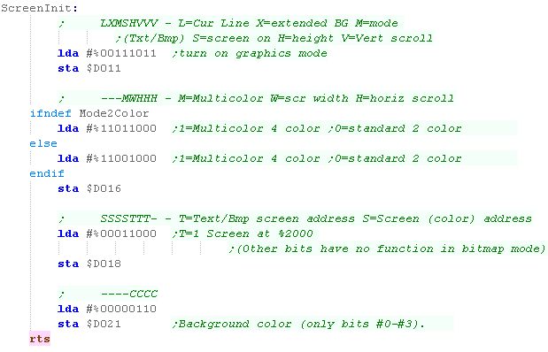
Setting up the screen
| We're going to turn on our screen using $D011, the settings
here will enable bitmap mode - which is what we're using in
these tutorials. Now we're going to set or color mode we use $D016 to do this... In these tutorials we'll support either 320x200 2 color mode, or 160x200 4 color mode, depending on whether the Mode2Color symbol is defined We've defined our screen mode, but we still need to define our memory locations... in bitmap mode only bit 3 has an effect, and we can only map our screen to $2000 or $0000 - as the zero page and stack are at $0000 we'll have to stick to $2000... we'll leave the color ram at $D800. Finally we'll set a background color, so we can see what we're doing! |
 |
Displaying our bitmap
| We're going to use the same code for the C64 as the BBC, We're using zero page addresses z_hl for the source data z_de for the destination... XY is the screen pos... The bitmap data was created with my AkuSprite editor included with the sources.7z because 8 consecutive bytes cover blocks of 8 Y-lines, we are calculating a memory address based on XY pos, transferring bitmap data from our bitmap to that memory location. once we've done a strip, we update our z_hl source, and repeat for the next strip. This will draw the character to the screen! |
 |
| The routine will work with 2 or 4 color graphics... but we need to export our bitmap in a different format - AkuSprite Editor can do both! |   |
| Have some
graphic you want to use as a bitmap or sprite? convert it to
C64 screen format with AkuSprite editor (in the sources.7z) It's free, open source, and supports saving graphics in the native format of ALL the systems in these tutorials! |
|
GetScreenPos
Because the screen memory is bitmapped, whenever we want to get pixels to the screen we just need to calculate the memory position by X,Y co-ordinate, and write data to that position The screen base is $2000 - and we need to split the bits of Y due to the odd layout odd the screen. Our formula is as follows: (X * 8) + (Top5BitsOfY * 40) + (Bottom3BitsOfY) + $2000 As there are bytes of 8 Y-lines between each column, we have to multiply our Xpos by 8
We split out the bottom 3 bits, these are marked as y below... we'll process them later... they are 0 when we do the multiply here The remaining 5 bits are the ones we need to multiply by 40 are marked Y...
Once we've calculated our X offset, and our Y offset from the top 5 bits, we need to add the screen offset $2000, and the bottom 3 bits of the Ypos... we've now calculated the memory address of the screen position in z_hl |
 |
| The C64 uses
'Color Attributes' to set the 2/4 colors of each square... We'll take a look at how this works in a later lesson, but if you want to do it now, the basics are here |
|
Common Data format for Joypad controls used by these tutorials
| In the Z80 tutorials we used registers HL for reading the
joystick... on the 6502 we'll use Zeropage addresses defined
as z_h and z_l... we'll use one bit per button on the
joystick/joypad for each bit, a 1 means the button is up (unpressed) a 0 means the button is down (pressed) We'll load player 1's joystick data into z_h... and player 2's into z_l |
|
||||||||||||||||||
| Our test program is very simple, all it does is read in the two controllers, and show the value of the z_h and z_l to the screen. | 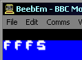 |
|
The BBC joysticks are analog, but we'll be treating them as digital, so we'll define a 'deadzone' in which the joystick is considered to be 'centered'... and once it's outside this range it will be considred Up,Down, Left or Right |
The BBC Analog Joystick (Joystick)
| The Joystick is analog on the
BBC... we need to read UD and LR, which will return a value
from 0-255.... On the BBC, Top Left of the joystick is 0,0... and Bottom Right is 255,255 |
X-Y Joystick Axis and returned 8 bit values: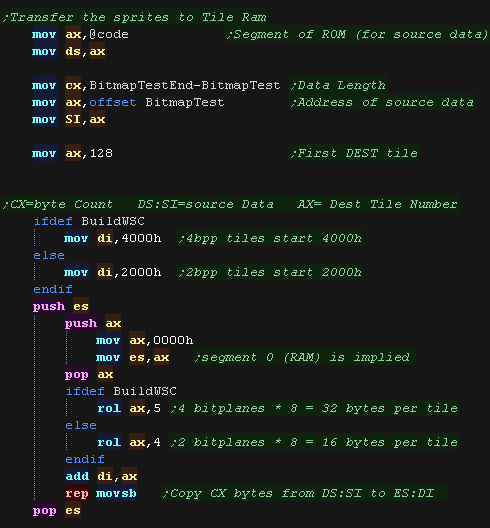 |
We read in from the ADC, which uses 4 addresses, though we only need 2...
| Port | R/W | Purpose | Bits | Details |
| $FEC0 | W | Data Latch / Conversation Start |
----MFCC | M=Mode (0=8 bit 1=10 bit)... F=Flag (usually 0)... CC=Channel (0/1 = joy1 2/3=joy2) |
| $FEC0 | R | Status | CBMMm-CC | C=Conversation complete (1=no)...B=busy... M=top two bits of conversiation... m=mode (8/10 bit)... CC=Channel |
| $FEC1 | R | High Data byte | DDDDDDDD | 8 Bit Data |
| $FEC2 | R | Low Data byte | DDDD---- | extra 4 low bits of 10/12 bit data |
When it comes to reading the Fire
buttons, because they are digital, they are separate, we use $FE40 -
part of the sound/keyboard controller!
| Port | Purpose | Bits | Details |
| $FE40 | Data Port | --JJBAAA | A=address (0=sound chip, 3=Keyboard) B=new setting for address AAA... J= Joystick Fire |
| $FE43 | Data Direction | DDDDDDDD | D=Direction (1=Write) |
Reading in from the Joysticks
| We're going to read in from Joystick 1 First we need to set the Data port to READ... we do this by writing 0 to $FE43 Now we need ro select the Analog Channel to read from, and store it's number in A... first we use Channel 0 (Left/Right) We'll use a function called ReadControlsGetData which will convert the data from a 0-255 'analog' value to two bits representing two joypad buttons (LR or UD)... these will be shifted into z_As in the zero page - we'll look at the function in hyst a moment Once we've done Channel 0 Left and Right... we'll do the same for Channel 1 for Up and Down... Now we've processed UDLR, the last thing todo is read in from the Joystick button - bit 4 of $FE40 |
 |
| We now do the same for Joystick
2... this time we use Channels 2 and 3, and bit 5 of $FE40 for
the fire button... We only read Joystick 2 in if UseDualJoy is defined... if we only have 1 player, we can save some memory by not reading the second joystick |
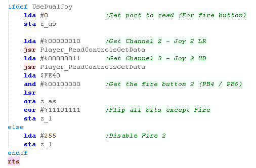 |
| BeebEm
only seems to support one Joystick... which is very
annoying! The code here SHOULD work with two though... Seeing as BeemEm can't use both, and your game may not require two, you can disable Joystick 2 if you don't define UseDualJoy... this will save some memory! |
|
Converting Analog (0-255) to Digital (L/R or U/D)
| We need to tell the hardware what channel we want to read...
the channel number is in A... and we write this to $FEC0 to
select the channel number. Now we need to wait for the data to be ready, we do this by reading from $FEC0, when the top bit is Zero, our data is ready! |
 |
| We're going to use a 'deadzone' of 192 - so if the value is
<32 we're going to consider it to be Left/Up... and if it's
>224 then it's going to be considered to be
Right/Down ... We use CLC, which sets the Carry to 0 - we'll rotate these into the z_as zeropage entry... so if no direction are pressed 00 will be rotated into z_as - this is inverted by the final EOR |
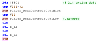 |
| Depending on whether we're high or low, we'll use SEC to rotate in a 1, or CLC to rotate in a 0 - this is inverted by the final EOR in the main function | 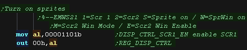 |
| View Options |
| Default Dark |
| Simple (Hide this menu) |
| Print Mode (white background) |
| Top Menu |
| ***Main Menu*** |
| Youtube channel |
| Patreon |
| Introduction to Assembly (Basics for absolute beginners) |
| Amazon Affiliate Link |
| AkuSprite Editor |
| ChibiTracker |
| Dec/Bin/Hex/Oct/Ascii Table |
| Alt Tech |
| Archive.org |
| Bitchute |
| Odysee |
| Rumble |
| DailyMotion |
| Please note: I wlll upload more content to these alt platforms based on the views they bring in |
| 68000 Content |
| ***68000 Tutorial List*** |
Learn 68000 Assembly  |
| Hello World Series |
| Platform Specific Series |
| Simple Samples |
| Grime 68000 |
| 68000 Downloads |
| 68000 Cheatsheet |
| Sources.7z |
| DevTools kit |
| 68000 Platforms |
| Amiga 500 |
| Atari ST |
| Neo Geo |
| Sega Genesis / Mega Drive |
| Sinclair QL |
| X68000 (Sharp x68k) |
| 8086 Content |
| Learn 8086 Assembly |
| Platform Specific Series |
| Hello World Series |
| Simple Samples |
| 8086 Downloads |
| 8086 Cheatsheet |
| Sources.7z |
| DevTools kit |
| 8086 Platforms |
| Wonderswan |
| MsDos |
| ARM Content |
| Learn ARM Assembly |
| Learn ARM Thumb Assembly |
| Platform Specific Series |
| Hello World |
| Simple Samples |
| ARM Downloads |
| ARM Cheatsheet |
| Sources.7z |
| DevTools kit |
| ARM Platforms |
| Gameboy Advance |
| Nintendo DS |
| Risc Os |
| Risc-V Content |
| Learn Risc-V Assembly |
| Risc-V Downloads |
| Risc-V Cheatsheet |
| Sources.7z |
| DevTools kit |
| MIPS Content |
| Learn Risc-V Assembly |
| Platform Specific Series |
| Hello World |
| Simple Samples |
| MIPS Downloads |
| MIPS Cheatsheet |
| Sources.7z |
| DevTools kit |
| MIPS Platforms |
| Playstation |
| N64 |
| PDP-11 Content |
| Learn PDP-11 Assembly |
| Platform Specific Series |
| Simple Samples |
| PDP-11 Downloads |
| PDP-11 Cheatsheet |
| Sources.7z |
| DevTools kit |
| PDP-11 Platforms |
| PDP-11 |
| UKNC |
| TMS9900 Content |
| Learn TMS9900 Assembly |
| Platform Specific Series |
| Hello World |
| TMS9900 Downloads |
| TMS9900 Cheatsheet |
| Sources.7z |
| DevTools kit |
| TMS9900 Platforms |
| Ti 99 |
| 6809 Content |
| Learn 6809 Assembly |
| Learn 6309 Assembly |
| Platform Specific Series |
| Hello World Series |
| Simple Samples |
| 6809 Downloads |
| 6809/6309 Cheatsheet |
| Sources.7z |
| DevTools kit |
| 6809 Platforms |
| Dragon 32/Tandy Coco |
| Fujitsu FM7 |
| TRS-80 Coco 3 |
| Vectrex |
| 65816 Content |
| Learn 65816 Assembly |
| Hello World |
| Simple Samples |
| 65816 Downloads |
| 65816 Cheatsheet |
| Sources.7z |
| DevTools kit |
| 65816 Platforms |
| SNES |
| eZ80 Content |
| Learn eZ80 Assembly |
| Platform Specific Series |
| eZ80 Downloads |
| eZ80 Cheatsheet |
| Sources.7z |
| DevTools kit |
| eZ80 Platforms |
| Ti84 PCE |
| IBM370 Content |
| Learn IBM370 Assembly |
| Simple Samples |
| IBM370 Downloads |
| IBM370 Cheatsheet |
| Sources.7z |
| DevTools kit |
| Super-H Content |
| Learn SH2 Assembly |
| Hello World Series |
| Simple Samples |
| SH2 Downloads |
| SH2 Cheatsheet |
| Sources.7z |
| DevTools kit |
| SH2 Platforms |
| 32x |
| Saturn |
| PowerPC Content |
| Learn PowerPC Assembly |
| Hello World Series |
| Simple Samples |
| PowerPC Downloads |
| PowerPC Cheatsheet |
| Sources.7z |
| DevTools kit |
| PowerPC Platforms |
| Gamecube |
| Work in Progress |
| ChibiAndroids |
| Misc bits |
| Ruby programming |
Buy my Assembly programming book
on Amazon in Print or Kindle!


Available worldwide!
Search 'ChibiAkumas' on
your local Amazon website!
Click here for more info!


Buy my Assembly programming book
on Amazon in Print or Kindle!
Available worldwide!
Search 'ChibiAkumas' on
your local Amazon website!
Click here for more info!
Buy my Assembly programming book
on Amazon in Print or Kindle!
Available worldwide!
Search 'ChibiAkumas' on
your local Amazon website!
Click here for more info!