

Platform Specific Lessons
Platform Specific Series - Now we
know the basics, lets look at the details of the platforms we're covering!

On the Atari 800 the main digital
Joysticks use 4 bits of the PIA - this PIA is not available on the
Atari 5200..
The ports!
The Atari 8000 and 5200 use a few different ports depending on the system, and what we want to read.
Atari 800 - UDLR
There are two ports we can read from, and each contains 2 joysticks, 4 bits per joystick for UDLR... these are in the correct order we want, and format
| There
are many differences between the port addresses on the
Atari 800 and 5200... most of these were just the hardware
developers being mean, and making sure the software for
the computer and console couldn't be shared... for some reason the PIA is not present on the console... maybe to save cost?... so we'll have to use analog joysticks on the 5200 |
 |
The ports!
The Atari 8000 and 5200 use a few different ports depending on the system, and what we want to read.
Atari 800 - UDLR
There are two ports we can read from, and each contains 2 joysticks, 4 bits per joystick for UDLR... these are in the correct order we want, and format
| Port | Address | Bits & Joystick | |
| PIA (800 only) | PORTA | $D300 | RLDURLDU 22221111 |
| PIA (800 only) | PORTB | $D301 | RLDURLDU 44443333 |
Atari 5200 - UDLR
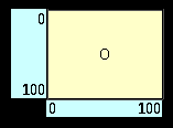
| On the Atari 5200 we need
to read in the analog paddles to get the X-Y position of
the joysticks... we need to read UD and LR, which will
return a value from 0-255.... On the Atari, Top Left of the joystick is 0,0... and Bottom Right is 255,255 |
X-Y Joystick Axis and returned 8 bit values: |
| Port | Atari 800 Address | Atari 5200 Address | Purpose | |
| POKEY | POT0 | $D200 | $C200 | game paddle 0 |
| POKEY | POT1 | $D201 | $C201 | game paddle 1 |
| POKEY | POT2 | $D202 | $C202 | game paddle 2 |
| POKEY | POT3 | $D203 | $C203 | game paddle 3 |
| POKEY | POT4 | $D204 | $C204 | game paddle 4 |
| POKEY | POT5 | $D205 | $C205 | game paddle 5 |
| POKEY | POT6 | $D206 | $C206 | game paddle 6 |
| POKEY | POT7 | $D207 | $C207 | game paddle 7 |
Atari 800 & 5200 - Fire
We also need to read the Joystick
trigger from Bit 0 of the trigger - this works on Atari 5200 and 800
| Port | Atari 800 Address | Atari 5200 Address | Purpose | |
| GTIA | TRIG0 | $D010 | $C010 | joystick trigger 0 |
| GTIA | TRIG1 | $D011 | $C011 | joystick trigger 1 |
| GTIA | TRIG2 | $D012 | $C012 | joystick trigger 2 |
| GTIA | TRIG3 | $D013 | $C013 | joystick trigger 3 |
Reading the Joystick on the Apple
800
Reading the Joystick on the Apple 5200
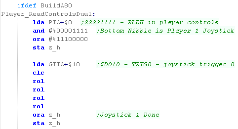
| We need to read in the player controls from PIA address 0
($D300)... the bottom nibble contains UDLR for player 1, so
we remove the top nibble... We now need to set the top 3 bits to 1, as we have no buttons for these positions. Finally we need to get the fire button... we get it from $10 in the GTIA ($D010)... the fire button is at bit 0, so we shift it left 4 times, and Or it into z_h z_h now contains all the controls for player 1 |
 |
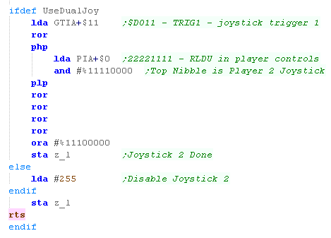
| We're now going to do the
same for Joystick 2... This time we use $D011 to get the Fire Button 2... we shift it's bit into the carry... and push the flags... Now we take the top nibble of $D300 to get player 2's buttons... After popping the flags, we shift right 4 times... this shifts the Fire as the 5th bit... After settng the top 3 unused bits to 1, we store this in z_l z_l now contains all the controls for player 2 |
 |
| Reading the fire buttons is the same on the 5200 (Though the port is different) - but everything else changes, as we now have to parse 'analog' (0-255) values and convert them into movements. |  |
Reading the Joystick on the Apple 5200
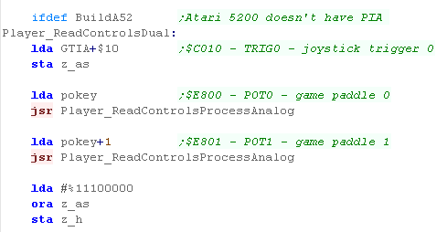
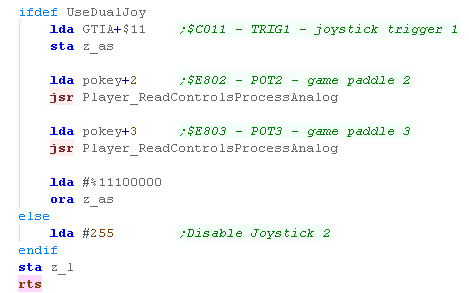
| On the Atari 5200 we can't use
the PIA to get UDLR - as it doesn't exist! We get the fire button from the GTIA in the same way as the Atari 800... but on the 5200 the address is different ($C010) We have to use the Pokey's analog's... Joystick 1 LR is handled by $E800 and UD is $E801 in the pokey We use a function called "ReadControlsProcessAnalog" which pushes two bits to represent the axis... Once we've done both axis, we OR the top unused 3 bits to set them to 1 |
 |
| We're now going to do the same
for Joystick 2... As before We use Trigger 1 in the GTIA at $C011 We also use analog Paddle 2 & 3 for LR and UD.of Joystick 2 And again we set the top 3 bits to 1 |
 |
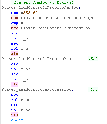
| When we convert Analog (0-255)
to Digital we're using a 'deadzone' of 128... so a value
<64 is Left/Up, and >192 is Right/Down We use SEC and ROL to shift a 1 into z_as to set a button as 'not pressed' We use CLC and ROL to shift a 0 into z_as to set a button as 'pressed' z_as will be transfered into z_h or z_l depending on the joystick being processed |
 |
 |
Once again, we may
not need both joysticks, and we can disable Joy 2 by not
defining UseDualJoy to save memory In fact the 'Jum52' emulator only seems to support a single joystick, so if you're using that, then there will be no benefit to the extra code for Joy 2 |

|
Lesson
P12 - Joystick Reading on the Apple II The Apple 2 also uses analog joysticks - we'll have to read in the analog values and convert them to digital, so we can use them in our game |
 |
 JoyTest.asm
|
|
 |
Analog to Digital
| On the Apple 2, we'll be using Analog Joysticks... these
return a value for the X and Y axis in a range of 0-100 0,0 is Top,Left.... 100,100 is Bottom,Right We're going to read these in and convert them to Digital Values |
 |
||||||||||||||||||
| In the Z80 tutorials we used registers HL for reading the
joystick... on the 6502 we'll use Zeropage addresses defined
as z_h and z_l... we'll use one bit per button on the
joystick/joypad for each bit, a 1 means the button is up (unpressed) a 0 means the button is down (pressed) We'll load player 1's joystick data into z_h... and player 2's into z_l |
|
||||||||||||||||||
| Our test program is very simple, all it does is read in the two controllers, and show the value of the z_h and z_l to the screen. | 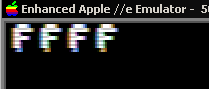 |
Ports relating to the Joystick
There are several ports we need to know about on the Apple II
Reading Analogs on the Apple II is a pain... we reset the analogs with $C070, then count up until bit 0 of $C064 (or one ofthe other analogs) becomes 1 - this value in our count is the analog position
In thory the Apple II as 4 switches (0-3) but we can only easily use 0 and 1
Each Joystick will use Two Analogs, 0 & 1 for Joystick 1, and 2 & 3 for Joystick 2
| Port | Name | Details | Notes |
| $C060 | BUTN3 | Switch Input 3 | Bit 7=0 when Down |
| $C061 | RDBTN0 | Switch Input 0 / Open Apple | Bit 7=0 when Down |
| $C062 | BUTN1 | Switch Input 1 / Solid Apple | Bit 7=0 when Down |
| $C063 | RD63 | Switch Input 2 / Shift Key | Bit 7=0 when Down |
| $C064 | PADDL0 | Analog Input 0 | Bit 7=0 when Count reached |
| $C065 | PADDL1 | Analog Input 1 | Bit 7=0 when Count reached |
| $C066 | PADDL2 | Analog Input 2 | Bit 7=0 when Count reached |
| $C067 | PADDL3 | Analog Input 3 | Bit 7=0 when Count reached |
| $C070 | PTRIG | Analog Input Reset | Reset Analog Count |
| Switch 2
isn't easy to use, as it seems to cause another firebutton
to trigger at the same time - and fire button 3 doesn't seem
to work at all! Maybe it's just the emulator used in these tutorials? |
 |
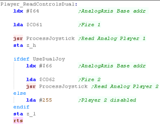
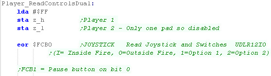
| When it comes to reading in
controls, we're going to specify the first of the two ports to
read in the X regsiter... We're then going to load in the Accumulator with the fire button for that joystick... The actual work is being done by the function ProcessJoystick - which will read in the data from the joystick and convert it how we want... We'll then store player 1's joystick on z_h... and player 2's in z_l |
 |
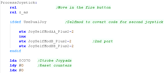
| We're going to use zero page
address z_as as a 'buildup' store for our data... we start by
shifting the fire button in! Now we're going to use self-modifying code to set up the following code to use the addresses for the two analogs we're going to use... So we can read in from the analogs, we need to reset the analogs, by reading $C070, We then reset the X and Y registers to 0... |
 |
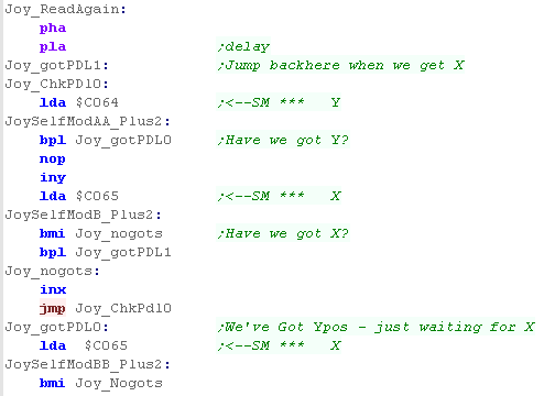
| The routine to read in the
joystick is tricky... What we effectively do is increment X until the top bit of $C065 reaches 1, and increment Y until the top bit of $C064 is 0.... The code is a bit complex though, as we don't know what order this will occur, |
 |
| We've got a function called
JoyConvertAnalog - this will covert the analog value in A to a
pair of bits, which will be pushed into z_as Our last action is to flip all the bits, and set the top 3 unused bits to 1 |
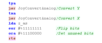 |
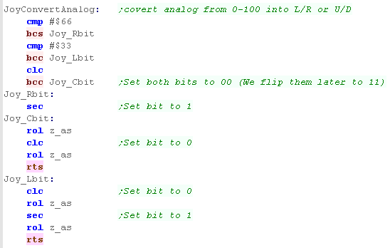
| When we need to convert Analog
to Digital, we'll use a deadzone of 33 T this means any value less than 33 is Left or Up... and any value Greater than 66 is Down or Right... as our last command flips the bits, we use CLC to push a 0 bit into z_as, or SEC to push a 1 in. |
 |
|
The Analog
reading code here was based on the example from Understanding
the
Apple II - page 7-24 If you want to learn more about the analog sticks, please see the manual - in fact it's the best resource for all Apple II stuff! |
 |
Lesson
P13 - Joystick Reading on the Atari Lynx The Lynx has a digital Joystick, 2 fires, 2 'option' buttons and a pause... Lets learn how to use them! |
|
JoyTest.asm
|
|
|
The Lynx Hardware
The Atari Lynx uses two memory mapped
ports for its buttons... but we'll only need one, as we'll ignore
the 'pause button' in this example - as we only use a single byte
for each player,
If a bit is 1 then the button is DOWN... if it's 0 then the button is UP
If a bit is 1 then the button is DOWN... if it's 0 then the button is UP
| Bits | |||||||||
| Port | Purpose | 7 | 6 | 5 | 4 | 3 | 2 | 1 | 0 |
| $FCB0 | Joystick | Up | Down | Left | Right | Option-1 | Option-2 | Inner Fire | Outer Fire |
| $FCB1 | Switches | - | - | - | - | - | Cart 1 Strobe | Cart 0 Strobe | Pause |
To match our other sysmtes, we need to
convert this to our standard format
If a bit is 0 then the button is DOWN... if it's 1 then the button is UP
Converting the bits
If a bit is 0 then the button is DOWN... if it's 1 then the button is UP
| Bit | 7 | 6 | 5 | 4 | 3 | 2 | 1 | 0 |
| Meaning | Start (Opt1) | F3 (Opt2) | F2 (Inner) | F1 (Outer) | Right | Left | Down | Up |
Converting the bits
| To start we need to do some setup! We're going to use ZeroPage entry z_h to store player 1's buttons - but we want to set z_l to all 1's - as this is usually used for player 2. We also need to flip the bits of $FCB0's data - so we EOR it in to the accumulator |
 |
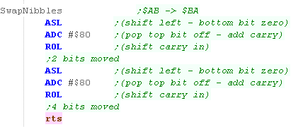
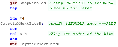
| We're going to need to swap the nibbles, we're going to
use a trick to achive this By using a combination of ASL,ADC and ROL we can shift two bits with three pairs, this is the fastest way to shift two bits on the 6502, We do this twice, effectively swapping the bottom and top half of the byte. |
 |
| We're going to swap the nibbles of the byte we read in
from the joystick, this moves the UDLR bits to the right
hand half of the byte, but they're in the wrong order! We need to flip the 4 bits around, and we do this by using ROR and ROL 4 times. |
 |
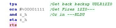
| Now we need to get the Firebuttons added... they're in the
right position and order... We AND them in - because we set all the bits of z_h to 1 at the start... Our byte is now in the right order! |
 |
| The Results will be shown onscreen as a pair of bytes! |  |
| For some
reason, even if you hold down the buttons, it seems the
Lynx will intermittantly register them as not pressed! It didn't cause any problems for Grime 6502 - but you may need to compensate if you're detecting if a button is held down. |
|
|
The Lynx supports
left handed play - if you press Pause+Option2 together, the
screen and controls should flip... but to support this you'll
have to do it in software... It just depends if you can be bothered to do the programming work to support the 'SouthPaws' ! |

The IO Port at $1000
Joypad reading is performed with Port $1000.... This port uses 4 bits for reading... so two reads from this port are needed to get the 8 buttons of a joypad... The PC Engine is capable of supporting up to 5 joypads, though we'll only read in two in these tutorials
Before we can start reading, we need to initialize the 'Multitap' (the hardware that toggles the joypads)... to do this we just write a #1 then #3 to port $1000... we need a short delay after each write....
Once the Multitap is initialized, we can get the button states by alternating writes of #1 and #0 to port $1000 - this will return the buttons of all 5 joysticks in order...
Common Data format for Joypad controls used by these tutorials
Reading in the joystick
Joypad reading is performed with Port $1000.... This port uses 4 bits for reading... so two reads from this port are needed to get the 8 buttons of a joypad... The PC Engine is capable of supporting up to 5 joypads, though we'll only read in two in these tutorials
Before we can start reading, we need to initialize the 'Multitap' (the hardware that toggles the joypads)... to do this we just write a #1 then #3 to port $1000... we need a short delay after each write....
Once the Multitap is initialized, we can get the button states by alternating writes of #1 and #0 to port $1000 - this will return the buttons of all 5 joysticks in order...
| Joypad | Select bit (Bit 0 $1000) |
7 | 6 | 5 | 4 | 3 | 2 | 1 | 0 |
| 1 | 1 | CD
addon (1=yes) |
Country (0=jpn) |
- | - | Left | Down | Right | Up |
| 1 | 0 | CD
addon (1=yes) |
Country (0=jpn) |
- | - | Run | Start | B | A |
| 2 | 1 | CD
addon (1=yes) |
Country (0=jpn) |
- | - | Left | Down | Right | Up |
| 2 | 0 | CD
addon (1=yes) |
Country (0=jpn) |
- | - | Run | Start | B | A |
| The PC
Engine actually supports 5 joypads, but Joypads 3-5 work
in exatly the same way, we just need to keep reading in
from the same port. |
|
Common Data format for Joypad controls used by these tutorials
| In the Z80 tutorials we used registers HL for reading the
joystick... on the 6502 we'll use Zeropage addresses defined
as z_h and z_l... we'll use one bit per button on the
joystick/joypad for each bit, a 1 means the button is up (unpressed) a 0 means the button is down (pressed) We'll load player 1's joystick data into z_h... and player 2's into z_l |
|
||||||||||||||||||
| Our test program is very simple, all it does is read in the two controllers, and show the value of the z_h and z_l to the screen. |  |
Reading in the joystick
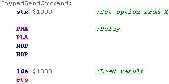
| We're going to need to do a lot of writes to the IO port
at $1000... we're going to use a common command called
'JoypadSendCommand'... This will write the value in X to $1000... wait a moment (Via PHA,PLA and two NOPs)... and read in the current state of the port... We'll use this for initialization, and for reading the joypads. |
 |
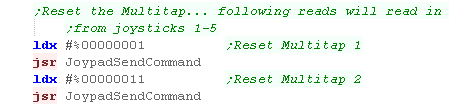
| Before we read in our Joysticks, we need to initialize the
Multitap.. .we just send #1, and then #3 to the port with
the command we just defined.. We don't actually need to read the result back, but it does no harm! |
 |
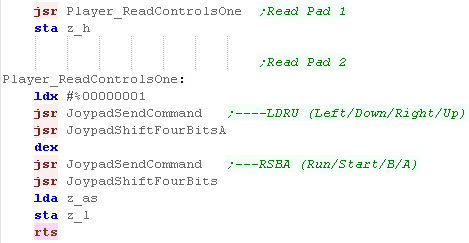
| The method for reading Joypad 1 and 2 is identical... in
both cases the procedure is as follows: We send a 1 to the port, and read in LDRU... Then we send a 0 to the port, and read in the fire buttons, and Start/Run We'll need to swap some of the bits around so LDRU becomes RLDU... we'll look at how we can do this in a moment. The results of Joypad 1 are stored in zero page entry z_h The results of Joypad 2 are stored in zero page entry z_L |
 |
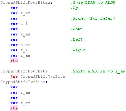
| We need to do some bit
shifting to swap the direction keys around, This is
done by JoypadShiftFourBitsA we use z_l as a temporary buffer for the bit we need to move... For the fire buttons, we don't need to shift any bits, we use JoypadShiftFourBits to do this we just move the 4 bits from A to z_as - shifting the bits in z_as to the right at the same time |
 |
 |
There are some 6 button joypads for the PC engine - primarily released so Street Fighter 2 could work well on the PC-Engine, but they're rare, and outside the scope of these tutorials... |


The Famicom Hardware
The NES has 2 joysticks, but 2 extra pads can be added to the Famicom external port... Unlike many systems, we can't read from one port to get all the keys in one go... we need to read each button one at a time, and build up a byte representing all the buttons in our joypad.
First we need to 'Strobe' the joypad, by writing 1 to bit $4016.... then we need to read in from $4016 and $4017 repeatedly to get all the bits of the Joypad... we'll see the source to do this in a moment.
When we read in 8 bits from the port, we'll end up with the following byte format for our buttons:
Presumably because of the planned backwards compatibility, the SNES
actually uses the same ports in the same way! However, because the
SNES has more buttons, we can do 16 reads rather than 8 to get the
extra buttons!
We're only going to read in the first 8 bits in this example, but if we wanted, we could read in another 4 to get X,A, L and R buttons
The SNES firmware also reads in these ports automatically, and stores these in ram - we can use these versions if we prefer!
Common Data format for Joypad controls used by these tutorials
Reading from the Hardware
On the Vic 20 we're going to use 2 hardware ports to read in our Joypad, We also need to set the direction of these ports... Port B is also used by the keyboard..
Common Data format for Joypad controls used by these tutorials
Reading from the Hardware
The NES has 2 joysticks, but 2 extra pads can be added to the Famicom external port... Unlike many systems, we can't read from one port to get all the keys in one go... we need to read each button one at a time, and build up a byte representing all the buttons in our joypad.
First we need to 'Strobe' the joypad, by writing 1 to bit $4016.... then we need to read in from $4016 and $4017 repeatedly to get all the bits of the Joypad... we'll see the source to do this in a moment.
| Mode | Port | Purpose | 7 | 6 | 5 | 4 | 3 | 2 | 1 | 0 |
| Write | $4016 | Strobe (reset) | - | - | - | - | - | - | - | Strobe |
| Read | $4016 | Joypad 1/3 | - | - | - | - | - | Mic | Pad3 | Pad1 |
| Read | $4017 | Joypad 2/4 | - | - | - | - | - | - | Pad4 | Pad2 |
When we read in 8 bits from the port, we'll end up with the following byte format for our buttons:
| 7 | 6 | 5 | 4 | 3 | 2 | 1 | 0 |
| Right | Left | Down | Up | Start | Select | B | A |
| While the
Famicom can support them, We won't be using Pad 3 or 4 in
these tutorials... We also won't be using the Microphone!... of course the Microphone is only supported by the Japanese model anyway. |
|
 |
The SNES Hardware |
We're only going to read in the first 8 bits in this example, but if we wanted, we could read in another 4 to get X,A, L and R buttons
| F | E | D | C | B | A | 9 | 8 | |
7 | 6 | 5 | 4 | 3 | 2 | 1 | 0 |
| - | - | - | - | R | L | X | A | Right | Left | Down | Up | Start | Select | Y | B |
The SNES firmware also reads in these ports automatically, and stores these in ram - we can use these versions if we prefer!
| Address | Name | Purpose | Bits |
| $4218 | JOY1L | Joypad #1 status (set during interrupt) | AXLR---- |
| $4219 | JOY1H | Joypad #1 status (if $4200 is set) | BYSTUDLR |
| $421A | JOY2L | Joypad #2 status | AXLR---- |
| $421B | JOY2H | Joypad #2 status | BYSTUDLR |
| $421C | JOY3L | Joypad #3 status | AXLR---- |
| $421D | JOY3H | Joypad #3 status | BYSTUDLR |
| $421E | JOY4L | Joypad #4 status | AXLR---- |
| $421F | JOY4H | Joypad #4 status | BYSTUDLR |
|
You can read from
$4218-$421F just fine - but in these tutorials we try to go
direct to the hardware itself... But it's up to you, you can use the alternates if you prefer! |
Common Data format for Joypad controls used by these tutorials
| In the Z80 tutorials we used registers HL for reading the
joystick... on the 6502 we'll use Zeropage addresses defined
as z_h and z_l... we'll use one bit per button on the
joystick/joypad for each bit, a 1 means the button is up (unpressed) a 0 means the button is down (pressed) We'll load player 1's joystick data into z_h... and player 2's into z_l |
|
||||||||||||||||||
| Our test program is very simple, all it does is read in the two controllers, and show the value of the z_h and z_l to the screen. | 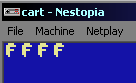 |
Reading from the Hardware
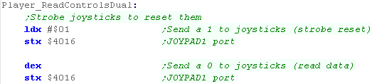
| This function will work on the NES or SNES! Our first stage of reading from the hardware is to initialize the Joypad hardware... we strobe the port to reset the hardware We do so by writing a 1 to $4016... this strobes the hardware We then need to write a 0 to $4016... this is to set up the port so we can read from it |
 |
| We now need to read in 8 times from the ports $4016 (for Joy1) and $4017 (for Joy2)... each time will read in a single button in bit 0... we then shift these bits into z_h and z_L | 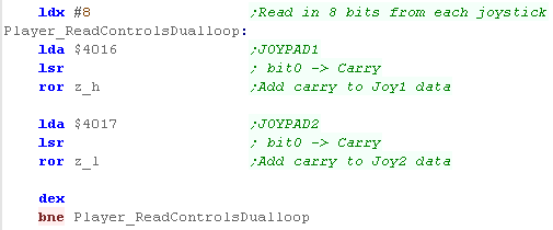 |
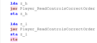
| We need to swap around the
keys for each controller from the format the (s)Nes gives
us, to our standard format, We use a function call to do this for us! |
 |
| We need to swap the bits
around in the top and bottom nibbles to match the format we
need... we use SwapNibbles to swap the UDLR and fire part of
the byte We also need to invert the bits... as we require a button that is down to be 0.... and up to be 1 |
 |

On the Vic 20 we're going to use 2 hardware ports to read in our Joypad, We also need to set the direction of these ports... Port B is also used by the keyboard..
| Address | Purpose | Bits | Detail |
| $911F | Port A | R------- | Joystick Right |
| $9120 | Port B | --FLDU-- | Joystick Fire,Up, Down, Left |
| $9122 | Data direction register B | DDDDDDDD | Direction 0=read 1=write |
| $9123 | Data direction register A | DDDDDDDD | Direction 0=read 1=write |
Common Data format for Joypad controls used by these tutorials
| In the Z80 tutorials we used registers HL for reading the
joystick... on the 6502 we'll use Zeropage addresses defined
as z_h and z_l... we'll use one bit per button on the
joystick/joypad for each bit, a 1 means the button is up (unpressed) a 0 means the button is down (pressed) We'll load player 1's joystick data into z_h... and player 2's into z_l |
|
||||||||||||||||||
| Our test program is very simple, all it does is read in the two controllers, and show the value of the z_h and z_l to the screen. | 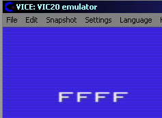 |
Reading from the Hardware
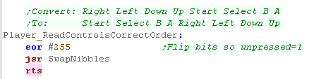
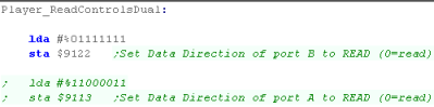
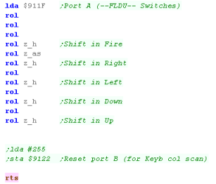
| We need to set bit 0 of port B to READ - we do this by
writing 127 to $9122 We also need to read from bits 2-5 of port A... but in practice we don't actually need to set this! |
 |
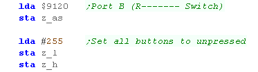
| Now we need to read in the 'Right' button... we'll store
this into z_as for later We then set all the bits of z_h and z_l to 1 .... we're only reading in one joystick, so we'll only use z_h |
 |
| We then read in the other
buttons from $911F, and shift them into z_h one by one We have to insert 'Right' in the correct position form z_as... Once we're done we can just return, though if we want to reset port B back to the correct state, we need to write 255, to set all its bits back to write... This would be needed by the firmware for keyboard reading. |
 |
| It
should be noted that the VIC can also support an analog
joystick, however it's outside of the scope of these
tutorials, which focus on digital controls. |
|

The BBC palette - and our one
Nibble per channel definition
| In these tutorials we use a fixed definition that uses two bytes per channel, we'll use one nibble to define each color, and we'll have to map these colors to the 8 colors the BBC is capable of | 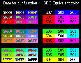 |
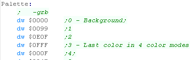
| Our palette definitions contain 4 nibbles... the first is
unused (0)... the second is the Green component, the third is
Red, and the last is Blue... This was based on the format used by the CPC+, and has become the standard for these tutorials. |
 |
| In these tutorials we'll define
a function called 'SetPalette'... it takes two parameters... A will contain a palette number (0= background)... on the BBC the maximum valid palette entry will be 3 zero page entries z_h and z_l are a two byte pair containing the color definition we want the color to have... this will be converted according to the capabilities of the hardware |
 |
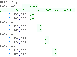
| On The BBC we use the
ULAConfig to set the palette, we saw this before when we
looked at setting up the bitmap screen. We have to set the
bottom nibble of 4 bytes per color, then send all the bytes to
the hardware, It's confusing and doesn't look very logical, but it works! |
|
Setting the ULA
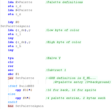
| We need to send 16 bytes to
the hardware to map the bitmap data in Ram to the Colors the
screen will show. Each Color 0-3 uses 4 bytes... The top Nibble is the Bitmap data color, we should leave it alone! The bottom Nibble is the palette color, this is what we want to change. |
 |
| We need to send the 16 bytes to the ULA hardware, at port $FE21, this will update the color information for the visible screen. | 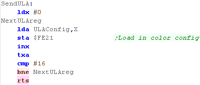 |
|
This code
will set the colors on ALL the systems in our 6502 tutorials
(where colors can be set!).... In fact, the -GRB color definitions in this example also work on the Z80 and 68000 systems in these tutorials - so you don't need to recalculate your palette when porting your game from one system to another! |
Setting the BBC palette
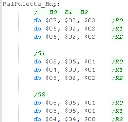
| We're going to use a 3x3x3
lookup table to convert the colors, this will be stored in
ram, and we'll use the formula Offset=(G*9)+(R*3)+B to calculate the color of the equivalent GRB color for the BBC |
 |
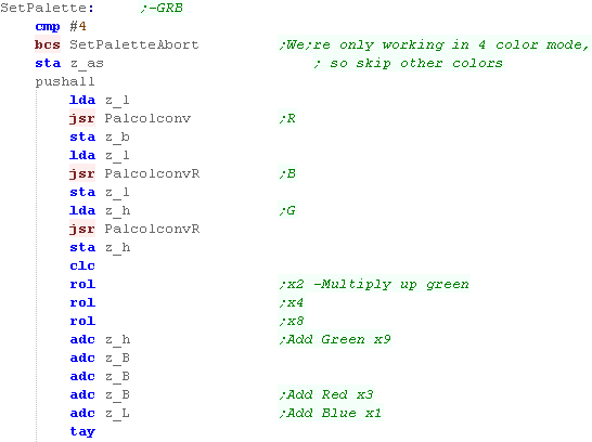
| When we call our SetPalette
function, we set A to the palette entry, and z_h and z_l as
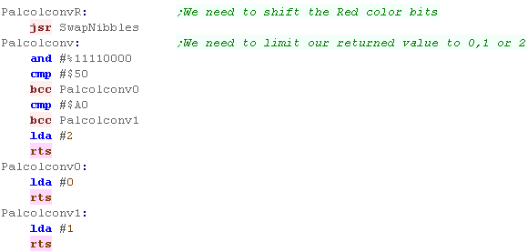
the word defining the new color (in $-GRB format) In the mode we're using, The BBC only uses 4 colors, so we'll skip any colors 4 or above. We then want to calculate the palette entry, using the formula we just mentioned... We're going to use two functions One is 'PalcolConv' - which will take a high nibble, and convert it to a value 0-2.... The other is PalConvR - which will take the low nibble and do the same.... Once we've calculated the offset, we store it into Y |
 |
| We're going to use that calculated offset, read the entry from the palette map, and store it into z_b | 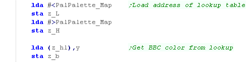 |
| Now we need to update the 4 entries of the 'ULAconfig' in ram that define that color... first we need to calculate the offset in that data, then we need to load z_hl with the pointer to the start of that config. | 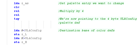 |
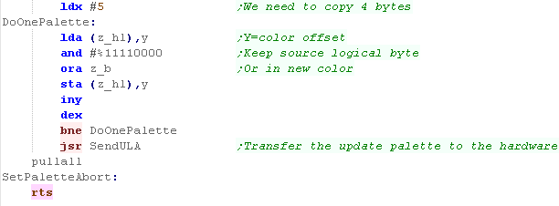
| We need to process all 4 bytes
of the config... we need to keep the top nibble, but set the
bottom nibble to the value we got from the lookup table. We repeat 4 times... finally we call SendULA to update the graphics hardware with the updated ULAConfig Our palette change is done! |
 |
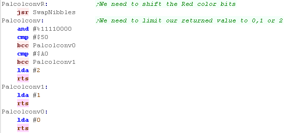
| Our palette conversion routines
use the following RGB conversions to convert a nibble to a
value 0-2 0-4...0 5-9...1 10-15...2 |
 |
| The SendULA
command is doing the work of transferring the colors to the
hardware... If you want to see how this command works, please see Lesson P1 from the tutorials |
|
The Atari Palette
The Atari colors uses two nibbles...
The high nibble is a color, and the low nibble is a brightness...
we'll have to use these for our colors
| xF | 0F | 1F | 2F | 3F | 4F | 5F | 6F | 7F | 8F | 9F | AF | BF | CF | DF | EF | FF |
| x8 | 08 | 18 | 28 | 38 | 48 | 58 | 68 | 78 | 88 | 98 | A8 | B8 | C8 | D8 | E8 | F8 |
| x0 | 00 | 10 | 20 | 30 | 40 | 50 | 60 | 70 | 80 | 90 | A0 | B0 | C0 | D0 | E0 | F0 |
When we want to set the 4 colors, we
use 4 memory addresses... the background is defined by $D01A...
Colors 1-3 are defined by $D016-8
| Name | Description | Address A80 | Address A52 |
| COLPF0 | Color/brightness of setcolor 0 | $D016 | $C016 |
| COLPF1 | color/brightness of setcolor 1 | $D017 | $C017 |
| COLPF2 | color/brightness of setcolor 2 | $D018 | $C018 |
| COLBK | color/brightness of setcolor 4 | $D01A | $C01A |
|
The We're
going to have to convert our GRB values to the Atari
palette... there won't be a 'perfect' mapping, but at least
we'll have something to start from... The reason we're doing this is to allow us to write multi platform code easily... you can always use an alternative mapping, or directly access the hardware for the Atari if these mappings don't suit your games needs |
| We're going to have to convert our 'ideal' GRB values into the nearest match for the Atari hardware. | 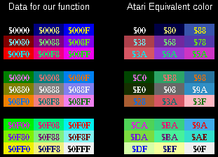 |
| Our palette definitions contain
4 nibbles... the first is unused (0)... the second is the
Green component, the third is Red, and the last is Blue... This was based on the format used by the CPC+, and has become the standard for these tutorials. |
|
| In these tutorials we'll define
a function called 'SetPalette'... it takes two parameters... A will contain a palette number (0= background)... on the BBC the maximum valid palette entry will be 3 zero page entries z_h and z_l are a two byte pair containing the color definition we want the color to have... this will be converted according to the capabilities of the hardware |
|
Setting the Atari Palette
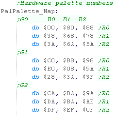
| We're going to use a 3x3x3
table of color conversions to convert our one nibble per
channel $-GRB definition to something valid for the Atari Offset=(G*9)+(R*3)+B to calculate the color of the equivalent GRB color for the BBC |
 |
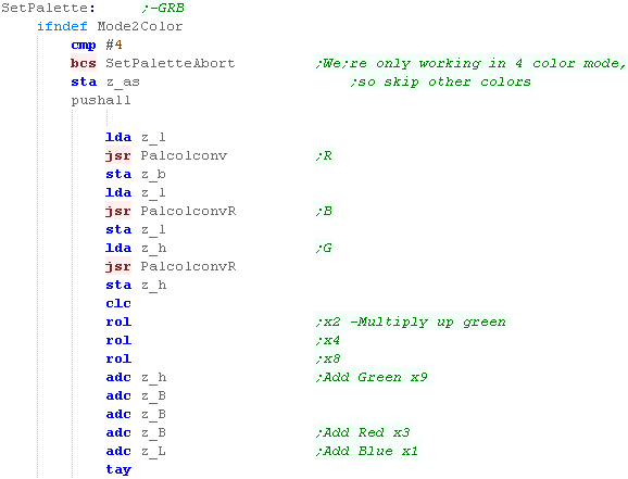
| When we call our SetPalette
function, we set A to the palette entry, and z_h and z_l as
the word defining the new color (in $-GRB format) In the mode we're using, The Atari only uses 4 colors, so we'll skip any colors 4 or above. We then want to calculate the palette entry, using the formula we just mentioned... We're going to use two functions One is 'PalcolConv' - which will take a high nibble, and convert it to a value 0-2.... The other is PalConvR - which will take the low nibble and do the same.... Once we've calculated the offset, we store it into Y |
 |
| Now we've worked out our offset, we can read in the new color definition from the palette | 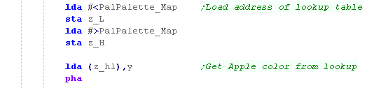 |
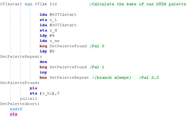
| We need to work out the correct
address to write to within the GTIA ($D016-D01A on the Atari
800 or $C016-C01A on the 5200) Color 0's address is $D01A Color 1's address is $D016 Color 2's address is $D017 Color 3's address is $D018 Once we've calculated the palette address to write to, we just output the new color we got from the lookup table to the destination address |
 |
| Our palette conversion routines
use the following RGB conversions to convert a nibble to a
value 0-2 0-4...0 5-9...1 10-15...2 |
 |
| It's
important to note that there may be discrepencies in the
exact colors depending on if the system is NTSC or PAL If you have problems, you can always use an alternative look up table for NTSC systems. |
|
Lynx Palette Ports
On the Lynx, Setting the palette is easy! we have 16 memory addresses to set the Green channel, and 16 to set the Blue and Red channels... each uses 4 bits per channel
On the Lynx, Setting the palette is easy! we have 16 memory addresses to set the Green channel, and 16 to set the Blue and Red channels... each uses 4 bits per channel
| From | To | Name | Bits |
| FDA0 | FDAF | Green � Colors (0-15) | -----GGGG |
| FDB0 | FDBF | Blue/Red � Colors (0-15) | BBBBRRRR |
| In these tutorials we use a common format on all systems - one nibble per channel in -GRB format... so all we need to do is convert that to -GBR format | |
Our Common Format
| Our palette definitions contain
4 nibbles... the first is unused (0)... the second is the
Green component, the third is Red, and the last is Blue... This was based on the format used by the CPC+, and has become the standard for these tutorials. |
|
| In these tutorials we'll define
a function called 'SetPalette'... it takes two parameters... A will contain a palette number (0= background)... on the BBC the maximum valid palette entry will be 3 zero page entries z_h and z_l are a two byte pair containing the color definition we want the color to have... this will be converted according to the capabilities of the hardware |
|
The Lynx Palette Code!
PC Engine Palette Ports
On the PC Engine we have 5 ports controling palette...
Writing 0 to $0400 will reset everything - we won't actually need this!
When we want to change a color we need to write a number (0-511) to $0402-$0403
We then write our color definition to $0404-$0405
| Because our source, and the
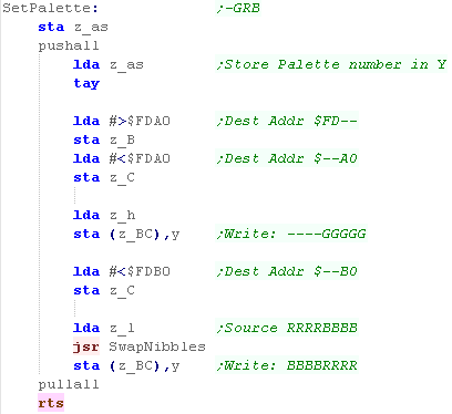
destination use 4 bits per channel our job is easy! We use zero page entry z_bc as a temp store for the address we're going to write to, we're going to write the Green part first, which goes in address $FDA0-$FDAF The number of the palette entry (0-15) was in A, but we store it in Y, so we can use it as an offset... First we write the Green part (in the lower nibble ----GGGG) from z_h... Next we change z_b to z, as we need to write the Red and Blue parts to ($FDB0-$FDBF) We want to write these from z_l, but they're in the wrong order, so we call SwapNibbles to swap RRRRBBBB to BBBBRRRR... |
 |
PC Engine Palette Ports
On the PC Engine we have 5 ports controling palette...
Writing 0 to $0400 will reset everything - we won't actually need this!
When we want to change a color we need to write a number (0-511) to $0402-$0403
We then write our color definition to $0404-$0405
|
|
Our Common Format
| Our palette definitions contain
4 nibbles... the first is unused (0)... the second is the
Green component, the third is Red, and the last is Blue... This was based on the format used by the CPC+, and has become the standard for these tutorials. |
|
| In these tutorials we'll define
a function called 'SetPalette'... it takes two parameters... A will contain a palette number (0= background)... on the BBC the maximum valid palette entry will be 3 zero page entries z_h and z_l are a two byte pair containing the color definition we want the color to have... this will be converted according to the capabilities of the hardware |
|
| These
Tutorials use a 34 bit per channel color definition, but the
PC Engine uses only 3, therefore 1 bit will be unused. It's a bit of a waste, but it means we can write code that works on all the systems more easily. |
|
|
In these examples we're going to set
Sprite and Backgroudn colors together, so we'll set palette
entry 0 and 256 at the same time... This will help make things easier for us when it comes to using sprites -which we'll do later! |
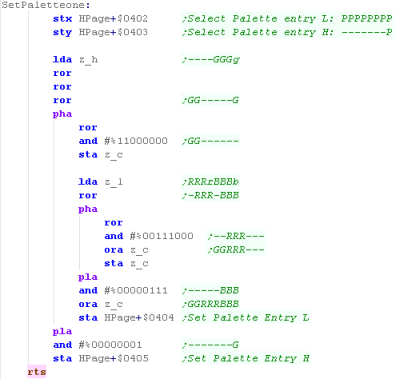
The PC-Engine Palette Code
| On the PC Engine, We'll only be using the 3 of 4 bit
definition, and we'll need to shift some of the bits around. To make using Hardware Sprites easier later, we'll also set the Sprite colors at the same time as the background ones |
|
||||||||||||||||||||||||||||||||||||||||||||||||||||||
| When we call SetPalette, A is the color number, and z_hl is
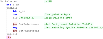
the color in -GRB format. We're going to set the Background (0-255) and Sprite (256-511) colors at the same time, so we're going to set two palette entries at the same time.. We set X to A... and Y to Zero (using CLY a special HuC6280 command) and set the background color... Then we set Y to 1 via inc... and set the equivalent sprite color! |
 |
||||||||||||||||||||||||||||||||||||||||||||||||||||||
| To select the palette entry we
want to change we write the low byte (now in X) to $0402, and
the high byte (in Y) to $0403 We now need to move all our bits around, we need to take 3 of the 4 bits of each color channel, and reposition them, Once the data is now in the correct format, we write the low byte to $0404, and the high byte to $0405 |
 |
| View Options |
| Default Dark |
| Simple (Hide this menu) |
| Print Mode (white background) |
| Top Menu |
| ***Main Menu*** |
| Youtube channel |
| Patreon |
| Introduction to Assembly (Basics for absolute beginners) |
| Amazon Affiliate Link |
| AkuSprite Editor |
| ChibiTracker |
| Dec/Bin/Hex/Oct/Ascii Table |
| Alt Tech |
| Archive.org |
| Bitchute |
| Odysee |
| Rumble |
| DailyMotion |
| Please note: I wlll upload more content to these alt platforms based on the views they bring in |
| 68000 Content |
| ***68000 Tutorial List*** |
Learn 68000 Assembly  |
| Hello World Series |
| Platform Specific Series |
| Simple Samples |
| Grime 68000 |
| 68000 Downloads |
| 68000 Cheatsheet |
| Sources.7z |
| DevTools kit |
| 68000 Platforms |
| Amiga 500 |
| Atari ST |
| Neo Geo |
| Sega Genesis / Mega Drive |
| Sinclair QL |
| X68000 (Sharp x68k) |
| 8086 Content |
| Learn 8086 Assembly |
| Platform Specific Series |
| Hello World Series |
| Simple Samples |
| 8086 Downloads |
| 8086 Cheatsheet |
| Sources.7z |
| DevTools kit |
| 8086 Platforms |
| Wonderswan |
| MsDos |
| ARM Content |
| Learn ARM Assembly |
| Learn ARM Thumb Assembly |
| Platform Specific Series |
| Hello World |
| Simple Samples |
| ARM Downloads |
| ARM Cheatsheet |
| Sources.7z |
| DevTools kit |
| ARM Platforms |
| Gameboy Advance |
| Nintendo DS |
| Risc Os |
| Risc-V Content |
| Learn Risc-V Assembly |
| Risc-V Downloads |
| Risc-V Cheatsheet |
| Sources.7z |
| DevTools kit |
| MIPS Content |
| Learn Risc-V Assembly |
| Platform Specific Series |
| Hello World |
| Simple Samples |
| MIPS Downloads |
| MIPS Cheatsheet |
| Sources.7z |
| DevTools kit |
| MIPS Platforms |
| Playstation |
| N64 |
| PDP-11 Content |
| Learn PDP-11 Assembly |
| Platform Specific Series |
| Simple Samples |
| PDP-11 Downloads |
| PDP-11 Cheatsheet |
| Sources.7z |
| DevTools kit |
| PDP-11 Platforms |
| PDP-11 |
| UKNC |
| TMS9900 Content |
| Learn TMS9900 Assembly |
| Platform Specific Series |
| Hello World |
| TMS9900 Downloads |
| TMS9900 Cheatsheet |
| Sources.7z |
| DevTools kit |
| TMS9900 Platforms |
| Ti 99 |
| 6809 Content |
| Learn 6809 Assembly |
| Learn 6309 Assembly |
| Platform Specific Series |
| Hello World Series |
| Simple Samples |
| 6809 Downloads |
| 6809/6309 Cheatsheet |
| Sources.7z |
| DevTools kit |
| 6809 Platforms |
| Dragon 32/Tandy Coco |
| Fujitsu FM7 |
| TRS-80 Coco 3 |
| Vectrex |
| 65816 Content |
| Learn 65816 Assembly |
| Hello World |
| Simple Samples |
| 65816 Downloads |
| 65816 Cheatsheet |
| Sources.7z |
| DevTools kit |
| 65816 Platforms |
| SNES |
| eZ80 Content |
| Learn eZ80 Assembly |
| Platform Specific Series |
| eZ80 Downloads |
| eZ80 Cheatsheet |
| Sources.7z |
| DevTools kit |
| eZ80 Platforms |
| Ti84 PCE |
| IBM370 Content |
| Learn IBM370 Assembly |
| Simple Samples |
| IBM370 Downloads |
| IBM370 Cheatsheet |
| Sources.7z |
| DevTools kit |
| Super-H Content |
| Learn SH2 Assembly |
| Hello World Series |
| Simple Samples |
| SH2 Downloads |
| SH2 Cheatsheet |
| Sources.7z |
| DevTools kit |
| SH2 Platforms |
| 32x |
| Saturn |
| PowerPC Content |
| Learn PowerPC Assembly |
| Hello World Series |
| Simple Samples |
| PowerPC Downloads |
| PowerPC Cheatsheet |
| Sources.7z |
| DevTools kit |
| PowerPC Platforms |
| Gamecube |
| Work in Progress |
| ChibiAndroids |
| Misc bits |
| Ruby programming |
Buy my Assembly programming book
on Amazon in Print or Kindle!


Available worldwide!
Search 'ChibiAkumas' on
your local Amazon website!
Click here for more info!


Buy my Assembly programming book
on Amazon in Print or Kindle!
Available worldwide!
Search 'ChibiAkumas' on
your local Amazon website!
Click here for more info!
Buy my Assembly programming book
on Amazon in Print or Kindle!
Available worldwide!
Search 'ChibiAkumas' on
your local Amazon website!
Click here for more info!