

The Interrupt Handler - Using Vblank!
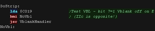
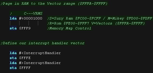
| We're going to define an interrupt handler for the IRQ
interrupt, We need to put this at address $FFFE-FFFF in memory, however by default this area is ROM! However we can page blocks of the rom out, and replace them with RAM via port $FFF9 |
|
||||||||||||||||||||||||||||||
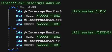
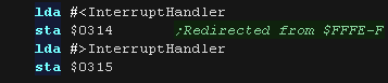
| Here we set bit 3 to one, This replaces the Vector area
with RAM ($FFFA-$FFFF) We can now load the address of our interrupt handler |
 |
||||||||||||||||||||||||||||||
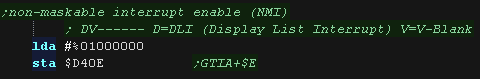
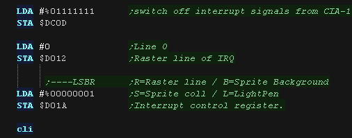
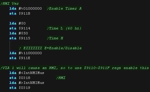
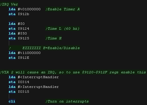
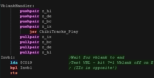
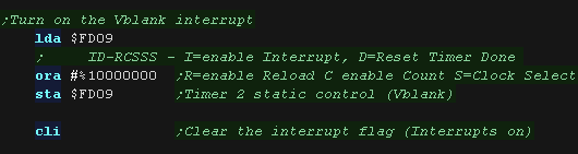
| Our Interrupt handler is ready, but we need
to tell the hardware to cause interrupts to occur! $FD09 controls interrupt generation, bit 7 will cause the Vblank to occur. We can now use CLI to allow the 6502 to accept interrupts |
 |
||||||||||||||||||||||||||||||
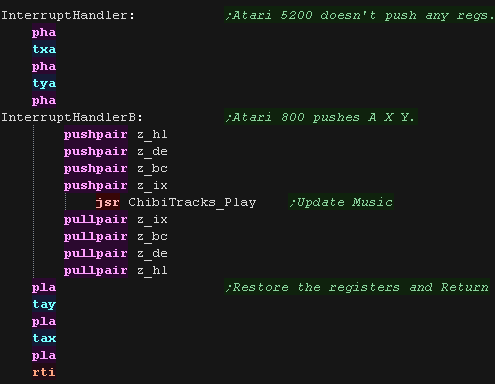
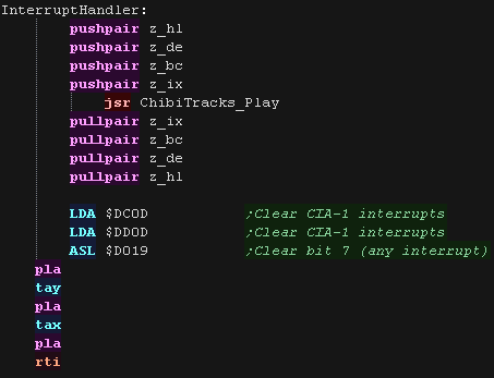
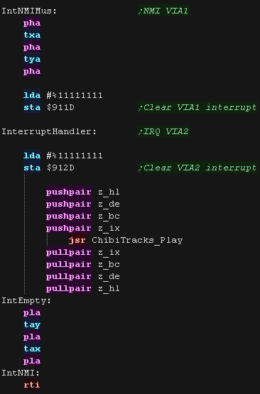
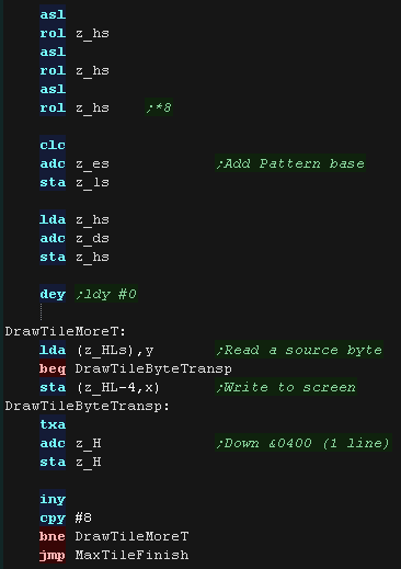
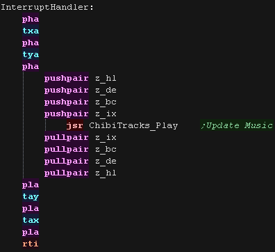
| Our interrupt handler just needs to update our music. ChibiTracks uses the Zeropage entries z_hl,z_bc,z_de and z_ix,as well as X,Y and A Our interrupt handler finishes with RTI - Interrupt handlers automatically back up and restore the flags (P) |
 |
ChibiTracks
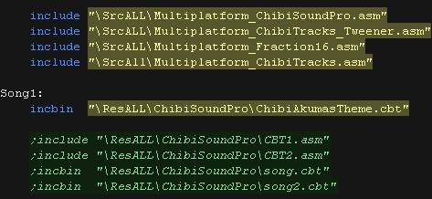
| To use ChibiTracks, we need to include the modules of the
music player, We also need the platform specific "Chibisound Pro" sound driver. We need to have a ChiBiTracks music file to play. |
 |
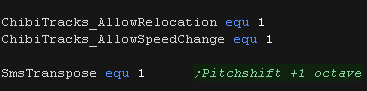
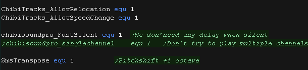
| We have two options 'Allow Speed change' allows us to
change the speed of our song. This is useful to keep the
song playing the same speed on 50hz and 60hz screens. NOTE:
Whether this will work effectively depends on if the speed
was pre-multiplied on export (faster playback, but stops
this function working) AllowRelocation allows the binary to be loaded at any memory address, not just the one 'compiled' into the binary at export time - while disabling this will save a little speed/memory it's recommended you keep this enabled! |
 |
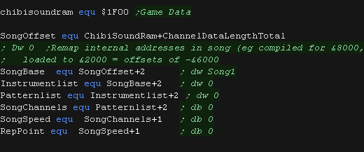
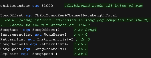
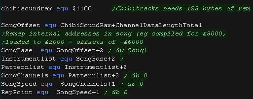
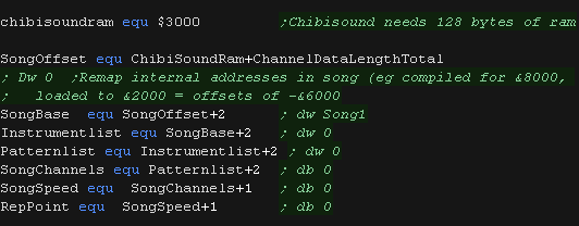
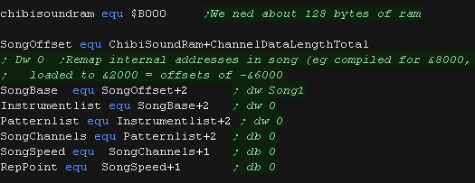
| We need to allocate up to 128 bytes of memory for
ChibiSoundPro, and ChibiTracks player. We define pointers to the ChibiTracks variables within this ram. |
 |
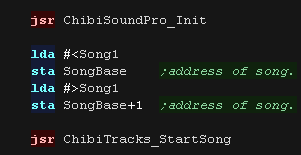
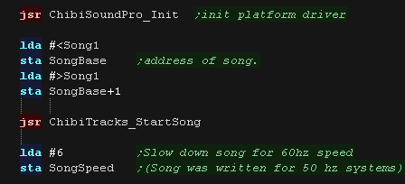
| Before we play anything we need to init the ChibiSoundPro
Driver. To start our song, we set SongBase to point to the music file we want to play, and call StartSong - we do this any time we want the music to change Here we've slowed down the song a little, it was designed to play on 50 hz systems. If our Lynx is configured with a 60hz screen we will want to slow the music down a little |
 |
| All that's left is to execute the PLAY routine to update the playing music. | |