

Learn Multi platform 6502 Assembly Programming... For Monsters!
Platform Specific Lessons
Platform Specific Series - Now we
know the basics, lets look at the details of the platforms we're covering!
The Interrupt Handler - Using Vblank!
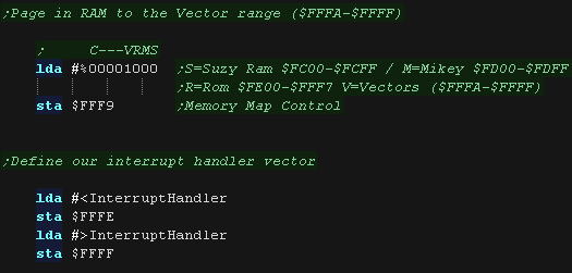
| We're going to define an interrupt handler for the IRQ
interrupt, We need to put this at address $FFFE-FFFF in memory, however by default this area is ROM! However we can page blocks of the rom out, and replace them with RAM via port $FFF9 |
|
||||||||||||||||||||||||||||||
| Here we set bit 3 to one, This replaces the Vector area
with RAM ($FFFA-$FFFF) We can now load the address of our interrupt handler |
 |
||||||||||||||||||||||||||||||
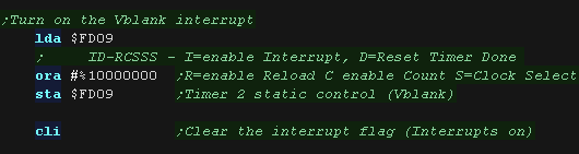
| Our Interrupt handler is ready, but we need
to tell the hardware to cause interrupts to occur! $FD09 controls interrupt generation, bit 7 will cause the Vblank to occur. We can now use CLI to allow the 6502 to accept interrupts |
 |
||||||||||||||||||||||||||||||
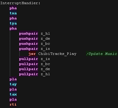
| Our interrupt handler just needs to update our music. ChibiTracks uses the Zeropage entries z_hl,z_bc,z_de and z_ix,as well as X,Y and A Our interrupt handler finishes with RTI - Interrupt handlers automatically back up and restore the flags (P) |
 |
ChibiTracks
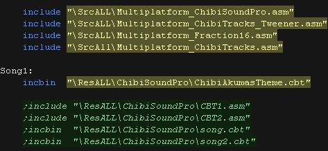
| To use ChibiTracks, we need to include the modules of the
music player, We also need the platform specific "Chibisound Pro" sound driver. We need to have a ChiBiTracks music file to play. |
 |
| We have two options 'Allow Speed change' allows us to
change the speed of our song. This is useful to keep the
song playing the same speed on 50hz and 60hz screens. NOTE:
Whether this will work effectively depends on if the speed
was pre-multiplied on export (faster playback, but stops
this function working) AllowRelocation allows the binary to be loaded at any memory address, not just the one 'compiled' into the binary at export time - while disabling this will save a little speed/memory it's recommended you keep this enabled! |
 |
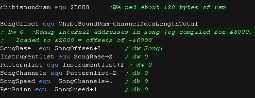
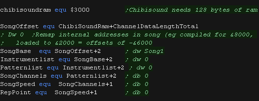
| We need to allocate up to 128 bytes of memory for
ChibiSoundPro, and ChibiTracks player. We define pointers to the ChibiTracks variables within this ram. |
 |
| Before we play anything we need to init the ChibiSoundPro
Driver. To start our song, we set SongBase to point to the music file we want to play, and call StartSong - we do this any time we want the music to change Here we've slowed down the song a little, it was designed to play on 50 hz systems. If our Lynx is configured with a 60hz screen we will want to slow the music down a little |
 |
| All that's left is to execute the PLAY routine to update the playing music. | |

The Interrupt Handler - Using Vblank!
| VBLANK causes an NMI interrupt, which executes the
vector at address $FFFA, however this is in ROM, which
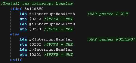
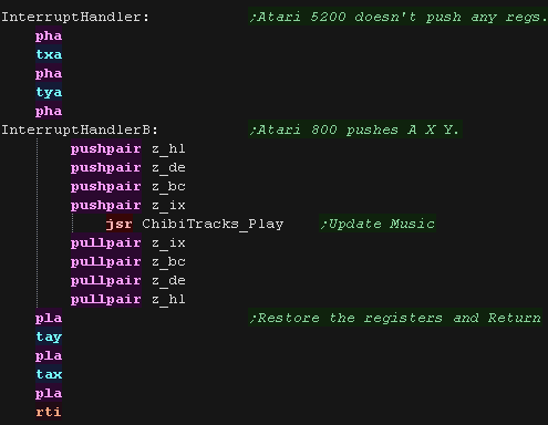
we cannot change! There is an address we can put the address of our interrupt handler, and the ROM will pass control to us. On the Atar5200 the ROM handler will pass control promptly to the subroutine at vector $0202 On the Atar800 the ROM handler will pass control promptly to the subroutine at vector $0222, Unlike the Atari 5022, The Atari 800 pushes the A, X and Y register before passing control, so we must pop these at the end of our interrupt handler. |
Atari 5200:
Atari 800
|
||||||||||||||||||||||||||||||||||||||||||||||||||||||||
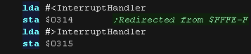
| We now load the address of the interrupt handler, We
load the address to $0202-3 on the Atari 5200 or $0222-3
on the Atari 800 as the Atari 800 pushes some registers for us, it's different for that system. |
 |
||||||||||||||||||||||||||||||||||||||||||||||||||||||||
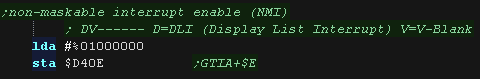
| Our Interrupt handler is ready, but we
need to tell the hardware to cause interrupts to occur! The GTIA controls NMI generation via address $D40E, We can enable V-Blank by setting bit 6 to 1 |
 |
||||||||||||||||||||||||||||||||||||||||||||||||||||||||
| Our interrupt handler just needs to update our music. ChibiTracks uses the Zeropage entries z_hl,z_bc,z_de and z_ix,as well as X,Y and A Our interrupt handler finishes with RTI - Interrupt handlers automatically back up and restore the flags (P) |
 |
| To use ChibiTracks, we need to include the modules of
the music player, We also need the platform specific "Chibisound Pro" sound driver. We need to have a ChiBiTracks music file to play. |
|
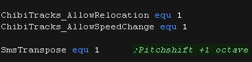
| We have two options 'Allow Speed change' allows us to
change the speed of our song. This is useful to keep the
song playing the same speed on 50hz and 60hz screens.
NOTE: Whether this will work effectively depends on if the
speed was pre-multiplied on export (faster playback, but
stops this function working) AllowRelocation allows the binary to be loaded at any memory address, not just the one 'compiled' into the binary at export time - while disabling this will save a little speed/memory it's recommended you keep this enabled! SMSTranspose is offered on systems which have trouble with very low tones (including the Ataris), this shifts all the octaves up by one. |
 |
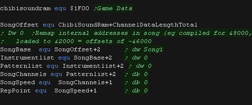
| We need to allocate up to 128 bytes of memory for
ChibiSoundPro, and ChibiTracks player. We define pointers to the ChibiTracks variables within this ram. |
 |
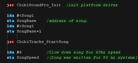
| Before we play anything we need to init the
ChibiSoundPro Driver. To start our song, we set SongBase to point to the music file we want to play, and call StartSong - we do this any time we want the music to change Here we've slowed down the song a little, it was designed to play on 50 hz systems. If our Lynx is configured with a 60hz screen we will want to slow the music down a little |
|
| All that's left is to execute the PLAY routine to update the playing music. | |

The Interrupt Handler - Using
Vblank!
| Our Vblank will causes an IRQ interrupt, which executes
the vector at address $FFFE-F, however this is in ROM,
which we cannot change! There is an address we can put the address of our interrupt handler, and the ROM will pass control to us. On the C64 the IRQ interrupt is redirected to vector at $0314 The interrupt handler even pushes some registers for us! A, X and Y are pushed onto the stack before our routine is called. |
|
||||||||||||||||
| We now load the address of the interrupt handler, We
load the address to $0314-5 |
 |
||||||||||||||||
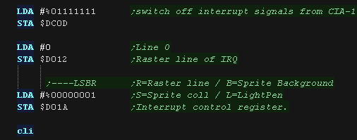
| We're going to cause a line interrupt at
line 0 to detect Vblank. We need to set $DC0D to the line we want the interrupt to occur (0) We need to turn on the line interrupt too! We do this with bit 0 of $D01A |
 |
||||||||||||||||
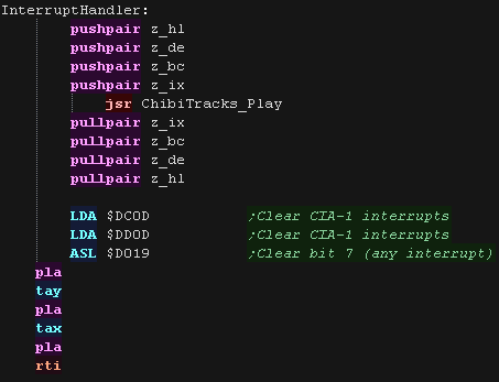
| Our interrupt handler just needs to update our music. ChibiTracks uses the Zeropage entries z_hl,z_bc,z_de and z_ix,as well as X,Y and A A, X and Y are pushed onto the stack before our routine is called, so we don't need to PUSH these, but we do need to PULL them! Our interrupt handler finishes with RTI - Interrupt handlers automatically back up and restore the flags (P) |
 |
ChibiTracks
| To use ChibiTracks, we need to include the modules of
the music player, We also need the platform specific "Chibisound Pro" sound driver. We need to have a ChiBiTracks music file to play. |
|
| We have two options 'Allow Speed change' allows us to
change the speed of our song. This is useful to keep the
song playing the same speed on 50hz and 60hz screens.
NOTE: Whether this will work effectively depends on if the
speed was pre-multiplied on export (faster playback, but
stops this function working) AllowRelocation allows the binary to be loaded at any memory address, not just the one 'compiled' into the binary at export time - while disabling this will save a little speed/memory it's recommended you keep this enabled! SMSTranspose is offered on systems which have trouble with very low tones (including the Ataris), this shifts all the octaves up by one. |
|
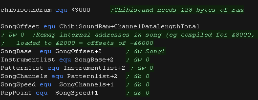
| We need to allocate up to 128 bytes of memory for
ChibiSoundPro, and ChibiTracks player. We define pointers to the ChibiTracks variables within this ram. |
 |
| Before we play anything we need to init the
ChibiSoundPro Driver. To start our song, we set SongBase to point to the music file we want to play, and call StartSong - we do this any time we want the music to change Here we've slowed down the song a little, it was designed to play on 50 hz systems. If our Lynx is configured with a 60hz screen we will want to slow the music down a little |
|
| All that's left is to execute the PLAY routine to update the playing music. | |

The Interrupt Handler - Using
timers.
| The VIC 20 does not have a Vblanks interrupt, however
we can use Timer1 to create a timed 50/60 hz interrupt
which will allow us to control the speed of our music We can use VIA1 or VIA2 to do this, but the kind of interrupt that occurs is different depending on which we use. Timer 1 on VIA 1 causes an NMI interrupt Timer 1 on VIA 2 causes an IRQ interrupt We can't directly change the interrupt vector, as the high memory area is ROM, however the rom firmware passes control to the vector addresses at $0314-$0319. The ROM for the IRQ handler backs up A,X and Y. the NMI one does not. |
|
||||||||||||||||
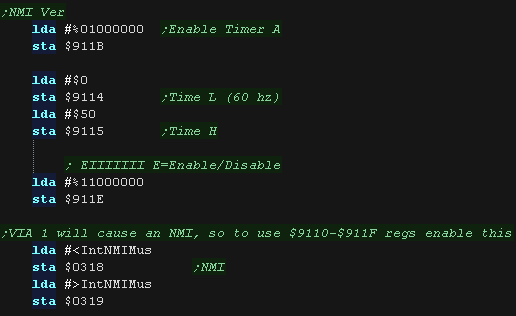
| If we want to use the NMI and
VIA1, we need to turn on the interrupt with
port $911E. We also need to turn on the timer with $911B Bit 7 defines if we're turning ON or OFF the interrupt. We load our time speed into $9114-5 (lower is faster) We then load the address of our interrupt handler to $0318-9 |
 |
||||||||||||||||
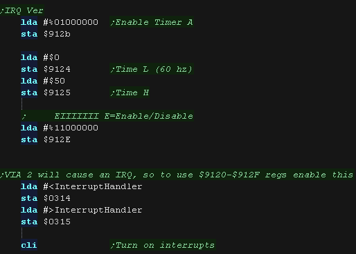
| If we want to use the IRQ
and VIA2, we need to turn on the interrupt
with port $912E. We also need to turn on the timer with $912B Bit 7 defines if we're turning ON or OFF the interrupt. We load our time speed into $9124-5 (lower is faster) We then load the address of our interrupt handler to $0314-5 |
 |
||||||||||||||||
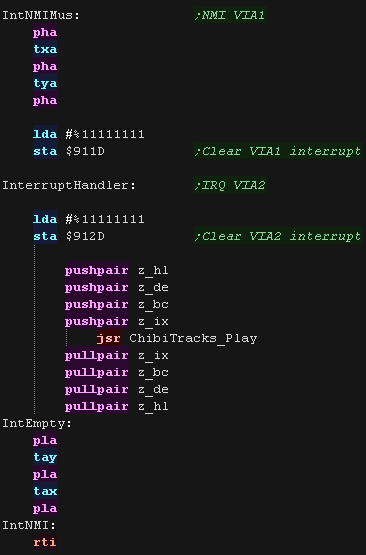
| If we used the NMI/VIA1, then we need to push A,X and
Y We now need to clear any interrupts pending, if we don't, the interrupt will fire again, and our music will play super fast. To do this we write 255 to $911D for VIA1/NMI or $912D for VIA2/IRQ We now need to update the music! ChibiTracks uses the Zeropage entries z_hl,z_bc,z_de and z_ix,as well as X,Y and A |
 |
ChibiTracks
| To use ChibiTracks, we need to include the modules of
the music player, We also need the platform specific "Chibisound Pro" sound driver. We need to have a ChiBiTracks music file to play. |
|
| We have two options 'Allow Speed change' allows us to
change the speed of our song. This is useful to keep the
song playing the same speed on 50hz and 60hz screens.
NOTE: Whether this will work effectively depends on if the
speed was pre-multiplied on export (faster playback, but
stops this function working) On the VIC it would be easier just to change the timer frequency, but our song here wasn't saved with pre-multiplication, so we still need it enabled. AllowRelocation allows the binary to be loaded at any memory address, not just the one 'compiled' into the binary at export time - while disabling this will save a little speed/memory it's recommended you keep this enabled! |
|
| We need to allocate up to 128 bytes of memory for
ChibiSoundPro, and ChibiTracks player. We define pointers to the ChibiTracks variables within this ram. |
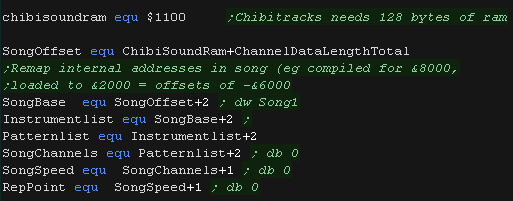 |
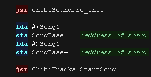
| Before we play anything we need to init the
ChibiSoundPro Driver. To start our song, we set SongBase to point to the music file we want to play, and call StartSong - we do this any time we want the music to change |
 |
| All that's left is to execute the PLAY routine to update the playing music. | |
 |
Lesson
P74 - Vblank timed Music on the Apple II (ChibiTracks) Lets upgrade our previous example with sound via ChibiTracks, we'll use the Vblank time playing some music |
 |
 AP2_MinTile_WithSound.asm
|
 |
 |
There
doesn't seem to be a way to use a Vblank interrupt on the
Apple 2, but we can detect Vblanks, and play our music when
it occurs. So long as we check for vblank regularly, it will work ok, though won't be as efficient as an interrupt |
Detecting Vblank
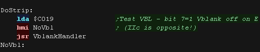
| To check for Vblank, we need to test bit 7 of $C019. If it's 0 then we're in Vblank (plus), otherwise we are not (minus) Annoyingly it's the opposite on the IIc! To ensure we catch the vblank, we'll test once per line draw in our graphics routine |
 |
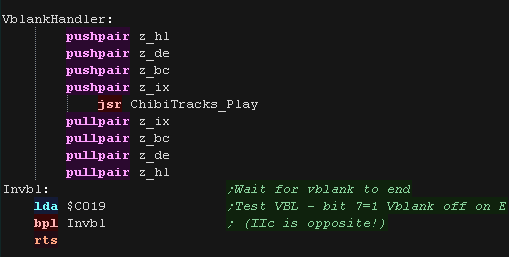
| We now need to update the music! ChibiTracks uses the Zeropage entries z_hl,z_bc,z_de and z_ix,as well as X,Y and A To ensure we don't update the music too often (unlikely unless silent!), we check to see if the Vblank has not finished, and wait until it has |
 |
ChibiTracks
| To use ChibiTracks, we need to include the modules of the
music player, We also need the platform specific "Chibisound Pro" sound driver. We need to have a ChiBiTracks music file to play. |
|
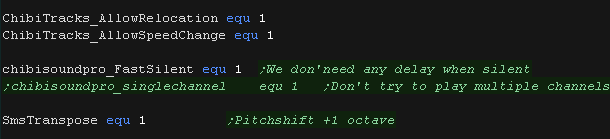
| 'Allow Speed change' allows us to change the
speed of our song. This is useful to keep the song playing the
same speed on 50hz and 60hz screens. NOTE: Whether this will
work effectively depends on if the speed was pre-multiplied on
export (faster playback, but stops this function working) On the VIC it would be easier just to change the timer frequency, but our song here wasn't saved with pre-multiplication, so we still need it enabled. AllowRelocation allows the binary to be loaded at any memory address, not just the one 'compiled' into the binary at export time - while disabling this will save a little speed/memory it's recommended you keep this enabled! FastSilent is specific to the Apple II, as the CPU is busy when playing sound, usually we pause when the sound is silent, but if we're controlling the playback speed in another way (like our vblank check) this just wastes cpu time. FastSilent will save this time, and allow us to draw more! SMSTranspose shifts the notes up 1 octave, this helps on systems where the low notes can't be well represented |
 |
| We need to allocate up to 128 bytes of memory for
ChibiSoundPro, and ChibiTracks player. We define pointers to the ChibiTracks variables within this ram. |
 |
| Before we play anything we need to init the ChibiSoundPro
Driver. To start our song, we set SongBase to point to the music file we want to play, and call StartSong - we do this any time we want the music to change |
|
| All that's left is to execute the PLAY routine to update the playing music. | |
 |
Lesson
P75 - Sound and Joypad on the Atari 2600 Lets Take a look at the Atari 2600 hardware. We'll create a combined example which used the Digital Joypad and sound hardware. |
|
A26_SoundJoy.asm
|
|
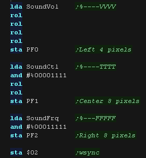
| We'll dump the
contents of the sound registers to the screen using playfield
registers PF0, PF1 and PF2.. This will allow us to see the bits in the registers, as vertical lines! |
 |
Sound registers
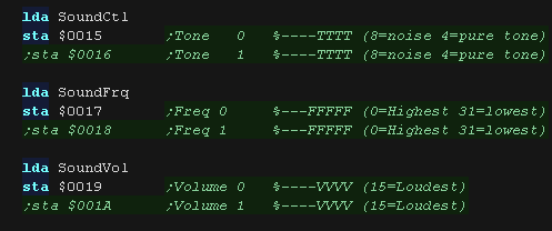
The Atari 2600 has 2 sound channels - though both are mono. Audio control selects one of 16 different waveforms for the sound.
| Category | Address | Name | Bits | Details |
| TIA_Write | $0015 | AUDC0 | ----TTTT | audio control 0 T=Tonetype (8=noise 4=pure tone) |
| TIA_Write | $0016 | AUDC1 | ----TTTT | audio control 1 T=Tonetype (8=noise 4=pure tone) |
| TIA_Write | $0017 | AUDF0 | ---FFFFF | audio frequency 0 (0=Highest 31=lowest) |
| TIA_Write | $0018 | AUDF1 | ---FFFFF | audio frequency 1 (0=Highest 31=lowest) |
| TIA_Write | $0019 | AUDV0 | ----VVVV | audio volume 0 (15=Loudest) |
| TIA_Write | $001A | AUDV1 | ----VVVV | audio volume 1 (15=Loudest) |
Joystick Registers
The Digital joypad directions can be read from the bits in port $2080,
1=not pressed 0=pressed
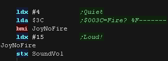
The Fire buttons can be read from the top bit of $003C/$003D, again 1=not
pressed 0=pressed
| Category | Address | Name | Bits | Details |
| TIA_Read | $0038 | INPT0 | 1....... | read pot port (Analog dial) |
| TIA_Read | $0039 | INPT1 | 1....... | read pot port (Analog dial) |
| TIA_Read | $003A | INPT2 | 1....... | read pot port (Analog dial) |
| TIA_Read | $003B | INPT3 | 1....... | read pot port (Analog dial) |
| TIA_Read | $003C | INPT4 | 1....... | read input (Fire 1 0=pressed) |
| TIA_Read | $003D | INPT5 | 1....... | read input (Fire 2 0=pressed) |
| PIA_RW | $0280 | SWCHA | 11111111 | Port A: I/O (read or write) Controller %RLDUrldu |
| PIA_RW | $0281 | SWACNT | 11111111 | Port A DDR, 0= input, 1=output |
| PIA_RW | $0282 | SWCHB | 11111111 | Port B; console switches (read only) %dD-C-SR |
| PIA_RW | $0283 | SWBCNT | 11111111 | Port B DDR (hardwired as input) |
| We can read in the digital direction buttons of the first digital
controller from address $0280. The direction buttons for controller 0 are in the top 4 bits... Controller 1 is in the bottom 4. These are in the format %RLDUrldu... 1=Not pressed 0=Pressed We test each direction and update variables in the zero page. |
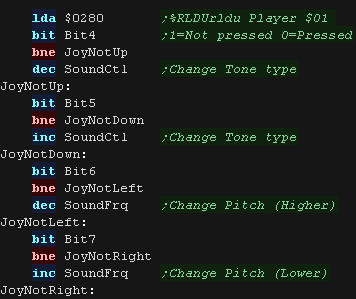 |
| The top bit of $003C contains the state of the first fire button. 1=Not pressed 0=Pressed. If Fire is pressed, we change the volume to 15, making it loud! |
 |
| If we're using sound channel 0 we use sound regs $15,$17 and $17 $0015 is the control port, the value here defines the tone type. $0017 is the frequency, 0 is the highest pitch. $0019 is the volume, 15 is the loudest. We can also use sound regs $16,$18 and $1A for sound channel 2 |
 |
| So we can visualize the register contents, we show the values to
the screen with PFO/PF1 and PF2 |
 |
|
Lesson
P76 - Joystick and Sprite on the Atari 2600 Lets take a look at the sprite hardware. Once again we'll use the joystick, this time to move a sprite around the screen! |
|
A26_Sprite.asm
|
|
| Like the playfield, The player 'Sprite' isn't a self
generating object, it's a single
byte register, which we will need to change each line to generate
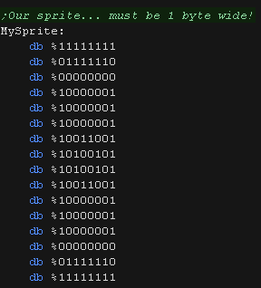
an image. To make this clear, we'll fill it with a single pixel line for the 'out of area' pixels. Our intended sprite is a box shape and moves with the joypad. Even positioning the sprite is hard... The X position is defined by a sync to the raster beam pos. The Y position is simply decided buy when we start sending our sprite data to the Sprite register GRP0 ($001B) |
 |
| The atari 'Player sprite' is 8 pixels wide, and the entire height
of the screen. By changing the data in the sprite register GRP0 ($001B) at the correct 'Y line' we can make the sprite move up and down with the joystick |
 |
| The sprite can only be 8 pixels wide, but we can 'scale it' to 2x
or 3x width We can even have the sprite repeat 2 or 3 times! The Number and size are controlled by register $0004 (NUMSIZ0) |

  |
Sprite Registers
| Category
|
Address
|
Name | Bits | Details |
| TIA_Write | $0004 | NUSIZ0 | --MMPPP | number-size player-missile 0 |
| TIA_Write | $0005 | NUSIZ1 | --MMPPP | number-size player-missile 1 |
| TIA_Write | $0006 | COLUP0 | CCCCLLLL | C=Color L=Luminance for Player & Missile 0 |
| TIA_Write | $0007 | COLUP1 | CCCCLLLL | C=Color L=Luminance for Player & Missile 1 |
| TIA_Write | $0010 | RESP0 | <strobe> | reset player 0 |
| TIA_Write | $0011 | RESP1 | <strobe> | reset player 1 |
| TIA_Write | $0012 | RESM0 | <strobe> | reset missile 0 |
| TIA_Write | $0013 | RESM1 | <strobe> | reset missile 1 |
| TIA_Write | $0014 | RESBL | <strobe> | reset ball |
| TIA_Write | $001B | GRP0 | BBBBBBBB | graphics player 0 |
| TIA_Write | $001C | GRP1 | BBBBBBBB | graphics player 1 |
| TIA_Write | $001D | ENAM0 | ......1. | graphics (enable) missile 0 |
| TIA_Write | $001E | ENAM1 | ......1. | graphics (enable) missile 1 |
| TIA_Write | $001F | ENABL | ......1. | graphics (enable) ball |
| TIA_Write | $0020 | HMP0 | SSSS---- |
horizontal motion player 0 |
| TIA_Write | $0021 | HMP1 | SSSS---- | horizontal motion player 1 |
| TIA_Write | $0022 | HMM0 | SSSS---- | horizontal motion missile 0 |
| TIA_Write | $0023 | HMM1 | SSSS---- | horizontal motion missile 1 |
| TIA_Write | $0024 | HMBL | SSSS---- | horizontal motion ball |
| TIA_Write | $0025 | VDELP0 | .......1 | vertical delay player 0 |
| TIA_Write | $0026 | VDELP1 | .......1 | vertical delay player 1 |
| TIA_Write | $0027 | VDELBL | .......1 | vertical delay ball |
| TIA_Write | $0028 | RESMP0 | ......1. | reset missile 0 to player 0 |
| TIA_Write | $0029 | RESMP1 | ......1. | reset missile 1 to player 1 |
| TIA_Write | $002A | HMOVE | <strobe> | apply horizontal motion |
| TIA_Write | $002B | HMCLR | <strobe> | clear horizontal motion registers |
| TIA_Write | $002C | CXCLR | <strobe> | clear collision latches |
| At the start of our code we set the default XY Pos of our sprite,
we use two bytes in the zero page for this. We then set the size of our sprite using register $04 (NUMSIZ0) |
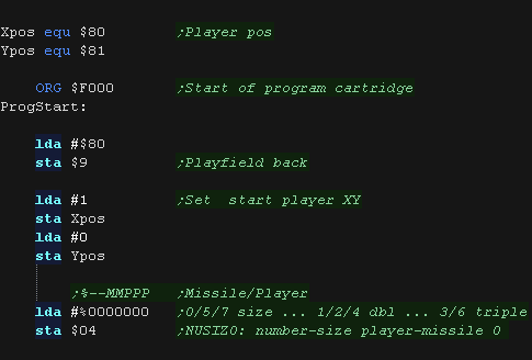 |
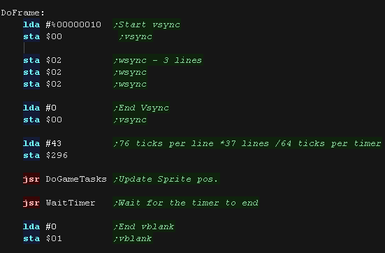
| At the start of our frame loop, we have to set our timing up for
Vblank. 'DoGameTasks' will handle joystick reading, and the X position of our sprite. |
 |
| We load the old XY pos into the X,Y registers - we'll use these if
we need to reset the sprite position due to it being out of bounds. We load in the directions from $0280 The direction buttons for controller 0 are in the top 4 bits... Controller 1 is in the bottom 4. These are in the format %RLDUrldu... 1=Not pressed 0=Pressed We test each direction and update variables in the zero page. |
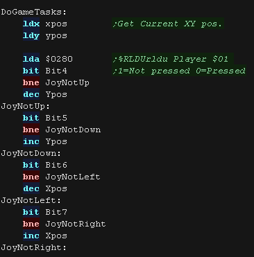 |
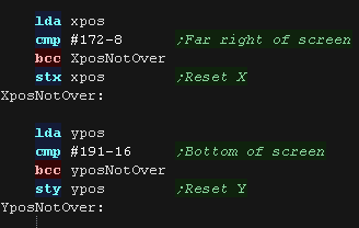
We now check the updated XYpos with the limits of the screen, if we've gone over the X or Y boundary, we reset the value. Going below 0 will result in a negative, which will also be reset by this code. |
 |
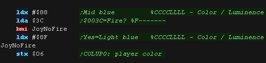
| We're going to set the color based on the fire button! The top bit of $003C contains the state of the first fire button. 1=Not pressed 0=Pressed. Register $0006 (COLUP0) defines the color of player 0 |
 |
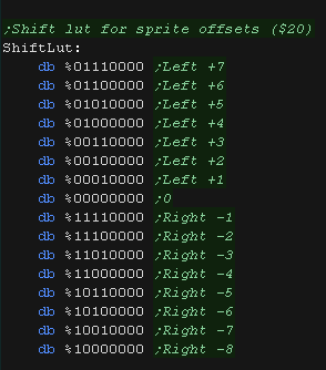
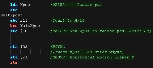
| We use the raster beam position to set the general Xposition, but
that isn't very accurate, we use HMP0 (Reg $0020 - Player Horizontal
Motion) to tweak the X pos. The Tweak is Left_7 to Right_8 We lookup the correct tweak via a lookup table. we apply it with reg $002A (HMOVE), but we don't actually apply it until we've set the approximate Xpos. |
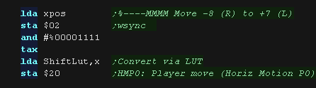  |
| We now count down the Xpos to approximate the beam position. Once we reach zero, we set the Xpos to the current beam position with reg $0010 (RESP0) this resets the player xpos to the current beam position. It's now time to apply the tweak using $002A (HMOVE). We need to do this after a WSYNC. |
 |
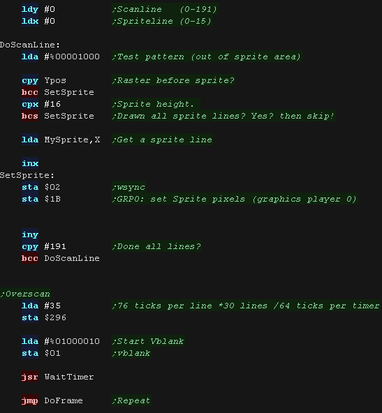
| Our sprite bitmap is 16 lines tall. it could be more or less, depending on how we transfer the data to the sprite register. |
 |
| During the drawing routine, Y is the current Y line of the screen. Once we reach the Ypos, we start counting the line of our sprite with X. We load the accumulator with %00001000, This is the value used for the sprite in the 'out of area' pixels... really it should probably be #0, but this makes it clearer that the sprite is drawn for the full height of the screen. During the sprite area (>Xpos <Xpos+16), we load a line from our sprite bitmap via 'MySprite,X' Whatever the position, we update the sprite pixel register $001B (GRP0) ... this defines the current bitmap for the player sprite. |
 |
 |
Lesson
P77 - MaxTile software tilemap on the BBC Lets take a look at the advanced 'Maxtile' tilemap on the BBC, it supports Xflip,Yflip, Fastfill and more! |
|
BBC_V1_MaxTile_Normal.asm
|
|
MaxTile Definitions
| Maxtile is optimized to work as efficiently as
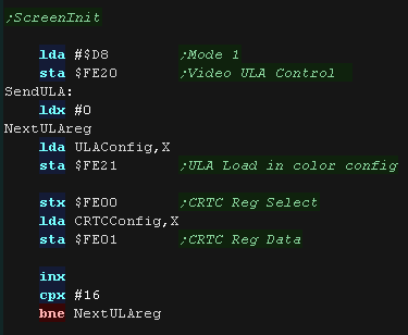
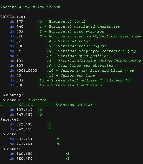
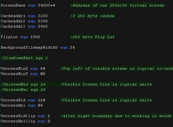
possible with the VRAM layout. the BBC version is designed to work with a 256x192 screen, as this gives the best compatibility with other systems. We send a sequence of values to the CRTC chip to set up the screen layout. Our Screenbase will be at $5000 |
  |
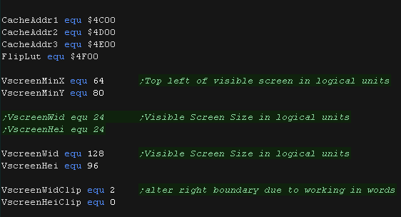
| We use some spare memory for the 3 draw caches (each 256 bytes) we also use 256 bytes for the 'Xflip lookup table' The screen is 256x192, which is 128x96 in logical units. The VRAM base of the screen is &5000. |
 |
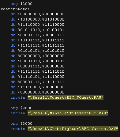
| Here is the Tile pattern data The BBC Tile Drawing routines use 4 color 8x8 tiles, So each tile uses 16 bytes. 'Fill tiles' are a special case, they fill a tile with 2 bytes (saving time and memory) |
 |
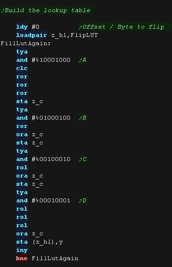
| The BBC Mode we're using has 4 pixels in each byte,
with 2 bits defining each pixel color. We'll calculate an Xflip LUT It would be too slow to shift these in realtime, so we 'precaclulate' the flipped equivalent of each of the 256 possible source bytes. This saves memory compared to storing alternative patterns. Yflip does not require a lookup table, we instead move UP VRAM instead of DOWN as we draw the pattern! |
 |
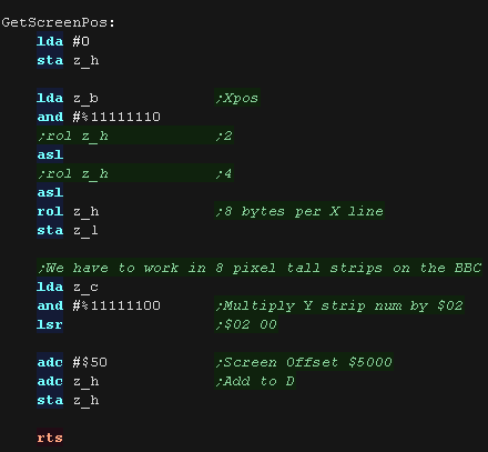
| When we want to draw a sprite object to the screen, we need to calculate the VRAM destination. MaxTile uses X,Y co-ordinates in 'Logical Units' (Pairs of pixels) - this is passed in BC, and the Vram destination is returned in HL The BBC screen layout is convenient for 8x8 tiles provided we draw aligned to an 8 pixel Y boundary. 8 consecutive bytes (Say from $5000-$5007) go down the screen, the 9th byte 'jumps back up 8 pixels to the next column. Therefore to move across 4 pixels we add 8 to our VRAM destination, and to move down an 8 pixels we add 512 (64*8) |
 |
Tile Drawing!
| The calling
routine that exexutes DrawTile will set X and Y to zero, so we
can rely on this being the case at the start of the routine...
however we need to ensure that X and Y still contain zero by the
end of our routine |
|
| The DrawTile Routine is called by the shared code, This shared
code will backup and restore the stack pointer and load the first
byte of the 16 bit tile number into A The low bit is shifted out (the update bit)... we need to reset it to 0 anyway! The following zero page entries are loaded: z_BCs = Tilemap z_DEs = Tile Bitmap Pattern data z_HL = VRAM Destination |
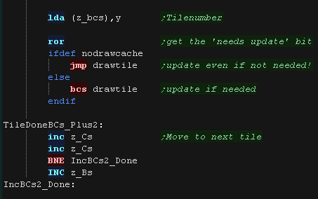 |
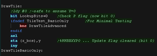
| To optimize things, the tile drawing works as a 'binary tree',
deciding the kind of tile drawing routine to use The Platform specific draw routine DrawTile starts by ckecking Bit 1 (now Bit 0) This is the 'Program' flag - If this is 0, then this is the simplest unflipped tile, otherwise we switch to the advanced routine. If we're drawing a basic tile, we shift a 0 back into A, and write it back, that clears the Update flag, as we will draw the tile now. |
 |
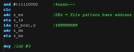
| We're going to draw a basic unflipped
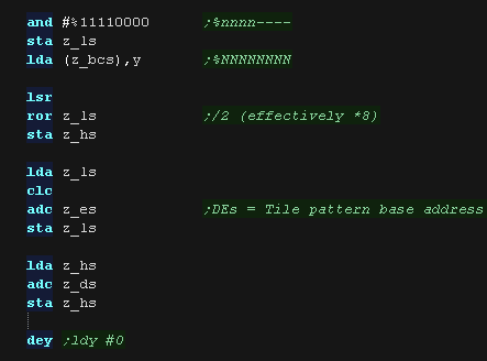
tile We need to load the second byte of the tilenumber, and add it to z_DE (the pattern data) This gives us the source address - which we load into z_HL |
 |
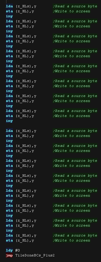
| We now use a huge 'unwrapped loop to move each line
of our source pattern to the screen. provided we're drawing to a vertically align As all the 16 bytes of our 8x8 tile are consecutive bytes we just use Y as an offset for our source pattern (z_HLs) and screen destination (z_HL) Note: the XY bits of the pattern number are unused in this case (They define flip mode if the Program bit was set)... These could be used for a 'Tile Tint' (for 4 color patterns on 16 color systems) or a bank number (for bankswitching huge tile sets) |
 |
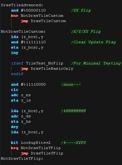
| If the Program bit was 1, then either we need to flip, or run
some 'custom code' Next we check the XY bits, if both are 0 this is not a flip (Transparent, Filled, Double etc) If either bit (or both) is 1, then this is some kind of flip, so we calculate the pattern source address, and move it into the z_HLs |
 |
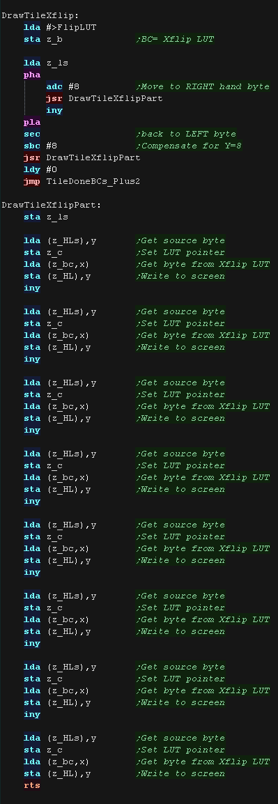
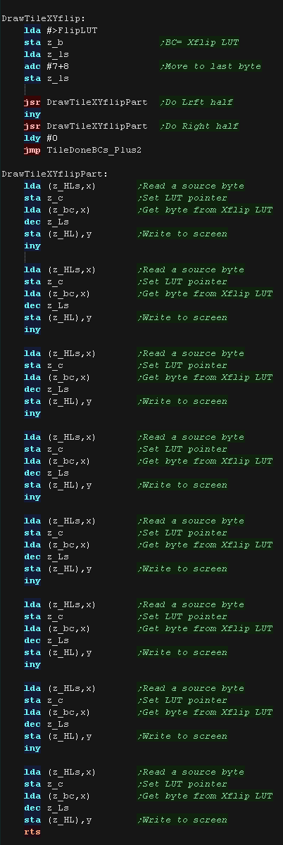
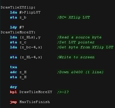
| If the Y flip bit is 0 we must be X flipping! We load each source pattern byte from z_HSs, then Xflip it via the Lookup table (in z_BC) We then write these to the screen in the same way as the unflipped data. We need to do the right hand half of the tile first, then the left, so we alter the HLs source pattern address, and execute DrawTileXflipPart twice to achieve this |
 |
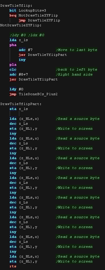
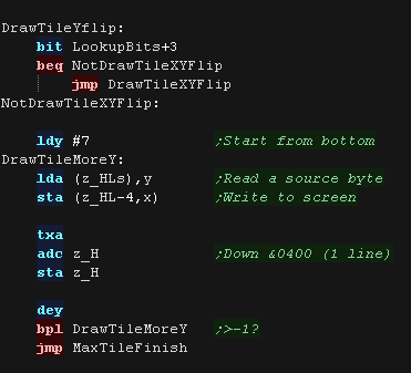
| If the Y flip bit was set we now check if the X
flip bit is also set. If it's not we're just Yflipping! To flip vertically we load the source pattern data normally, but we write it to the screen from the bottom of the tile upwards. |
 |
| if the X bit was set as well as Y we need to XY
flip. We do this with a combination of both 'tricks' We use the LUT to X flip, and draw to the screen Bottom to Top to Y flip! |
 |
MaxTile Custom Draw Types
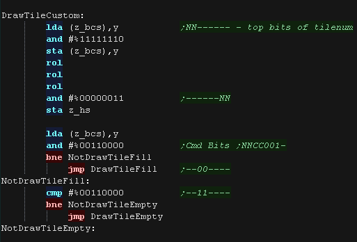
| Bits 1,2,3... XYP=%001 defines a custom program When a custom program is being used Bits 4,5 define the program type (rather than part of the low tile number) %00=Filled Tile %01=Double height tile %10=unused %11=Transparent tile/empty tile The remaining two bits 6,7 act as the High part of the tile number %------NN nnnnnnnn |
 |
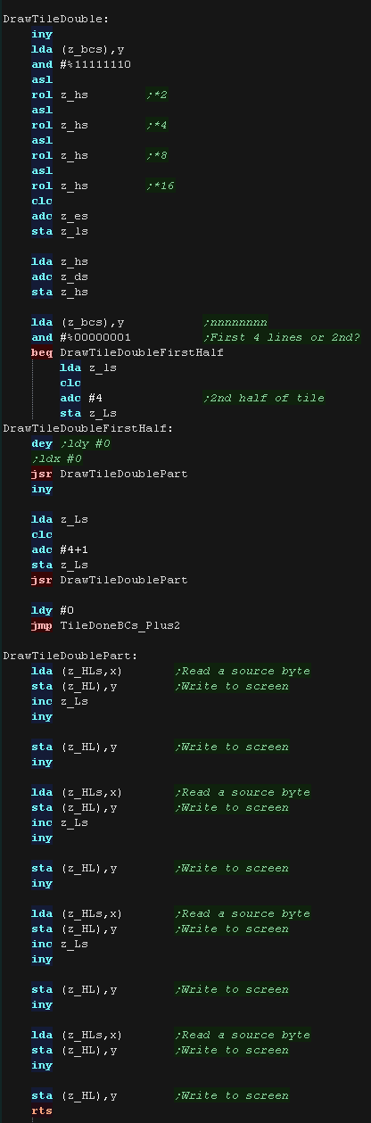
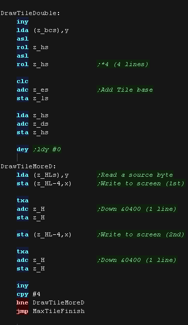
| A double height
tile uses only 4 lines of a pattern, so we multiply the pattern
number by 8 We then draw each line of the pattern twice to the screen. |
 |
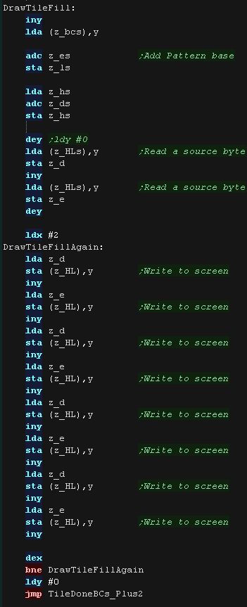
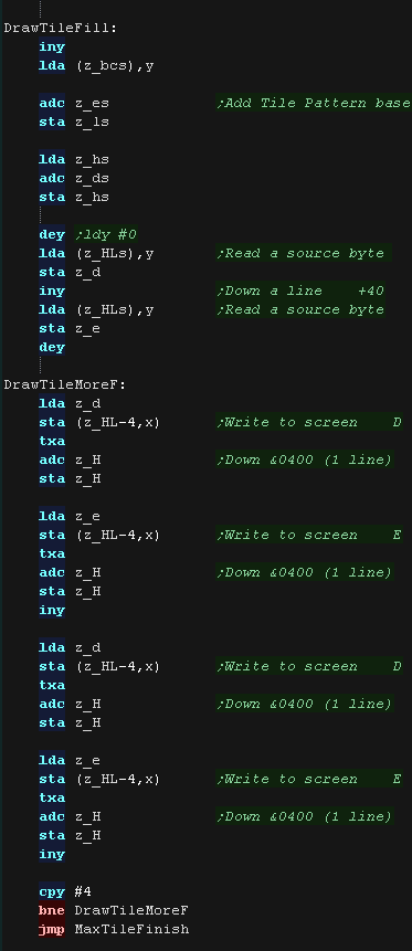
| The fill tile is
the simplest! We use 2 bytes from the pattern data, and fill each line with one of the two We use z_E for one line, then z_D for one line - this allows us to make a nice 'checkerboard' patterned fill, or alternate lines in different colors. As so little data is read, This routine is the fastest, so should be used for as much as possible of our tilemap! |
 |
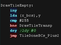
| The final type is the Transparent
tile. if the Tilenumber=255 then this tile is completely transparent, and no data will be drawn |
 |
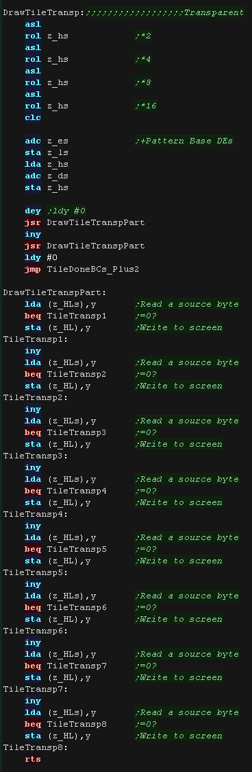
| Our transparency is a crude '0 byte' transparency. Basically, any byte equal to 0 is not drawn to the screen, others are drawn normally. We use the same pattern data as usual, but as we read in each byte, we only draw it to the screen if it isn't zero.. |
 |
|
Lesson
P78 - MaxTile software tilemap on the Apple II Lets take a look at the advanced 'Maxtile' tilemap on the Apple II , it supports Xflip,Yflip, Fastfill and more! |
|
AP2_V1_MaxTile_Normal.asm
|
|
MaxTile Definitions
| Maxtile Caches draws to the screen in 3 thirds to reduce
flicker. We use some spare memory for the 3 draw caches (each 256 bytes) we also use 256 bytes for the 'Xflip lookup table' The screen is 256x192, which is 128x96 in logical units, we add 4 to the screen base to center this screen. The VRAM base of the screen is &5000. |
 |
| Here is the Tile pattern data The Apple II Tile Drawing routines use 2 color 8x8 tiles (Actually 7x8 + 1 color bit!!!), So each tile uses 8 bytes. 'Fill tiles' are a special case, they fill a tile with 2 bytes (saving time and memory) |
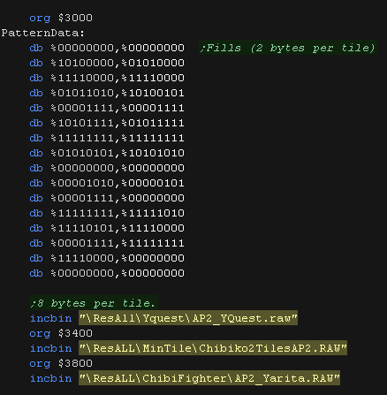 |
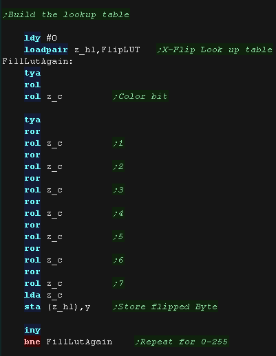
| The Apple II Mode we're using has 7 pixels in
each byte, with the first bit as a color bit. We'll calculate an Xflip LUT It would be too slow to shift these in realtime, so we 'precaclulate' the flipped equivalent of each of the 256 possible source bytes. This saves memory compared to storing alternative patterns. Yflip does not require a lookup table, we instead move UP VRAM instead of DOWN as we draw the pattern! |
 |
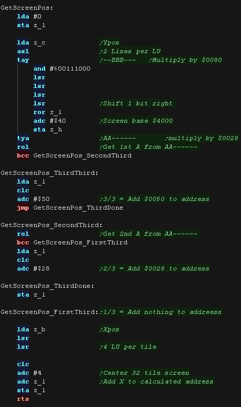
| When we want to draw a sprite object to the screen, we need to calculate the VRAM destination. MaxTile uses X,Y co-ordinates in 'Logical Units' (Pairs of pixels) - this is passed in z_BC, and the Vram destination is returned in z_HL The Apple II screen memory is a bit of a pain, as the screen is plit into thirds! The screen layout is split in 3 parts according to Y line %AABBBCCC - AA*$0028 BBB*$0080 CCC*$0400 We calculate the appropriate Y line with bit shifts and branches. We then add the Xpos in bytes, +4 to center the screen. The initial calculation is a pain, however moving down a tile is simple, we just add 4 to the top byte (z_H) of the Vram destination (z_HL |
 |
Tile Drawing!
| The calling
routine that exexutes DrawTile will set X and Y to zero, so we
can rely on this being the case at the start of the routine...
however we need to ensure that X and Y still contain zero by the
end of our routine |
|
| The DrawTile Routine is called by the shared code, This shared
code will backup and restore the stack pointer and load the first
byte of the 16 bit tile number into A The low bit is shifted out (the update bit)... we need to reset it to 0 anyway! The following zero page entries are loaded: z_BCs = Tilemap z_DEs = Tile Bitmap Pattern data z_HL = VRAM Destination |
|
| To optimize things, the tile drawing works as a 'binary tree',
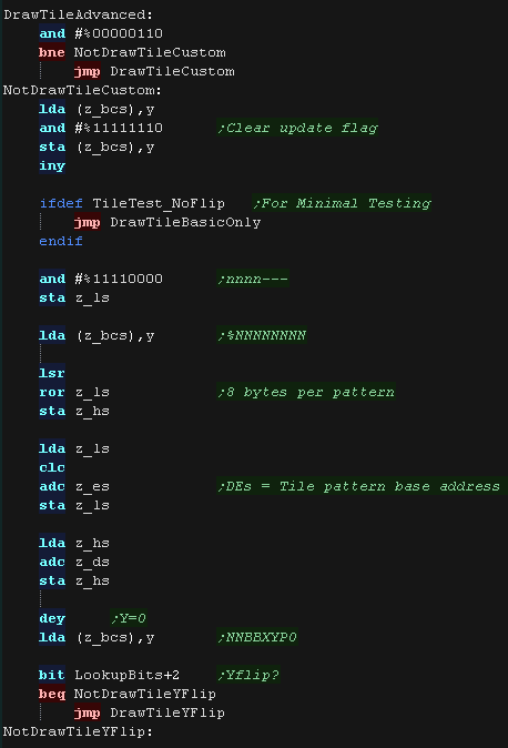
deciding the kind of tile drawing routine to use The Platform specific draw routine DrawTile starts by ckecking Bit 1 (now Bit 0) This is the 'Program' flag - If this is 0, then this is the simplest unflipped tile, otherwise we switch to the advanced routine. If we're drawing a basic tile, we shift a 0 back into A, and write it back, that clears the Update flag, as we will draw the tile now. We load X with 4, this speeds up our 'Downline commands' |
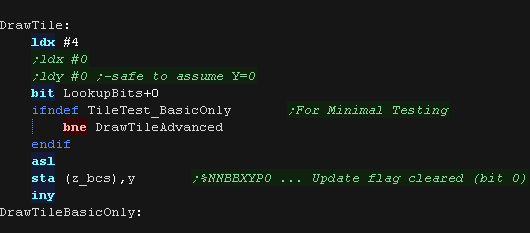 |
| We're going to draw a basic unflipped
tile We need to load the second byte of the tilenumber, and add it to z_DE (the pattern data) This gives us the source address - which we load into z_HL |
 |
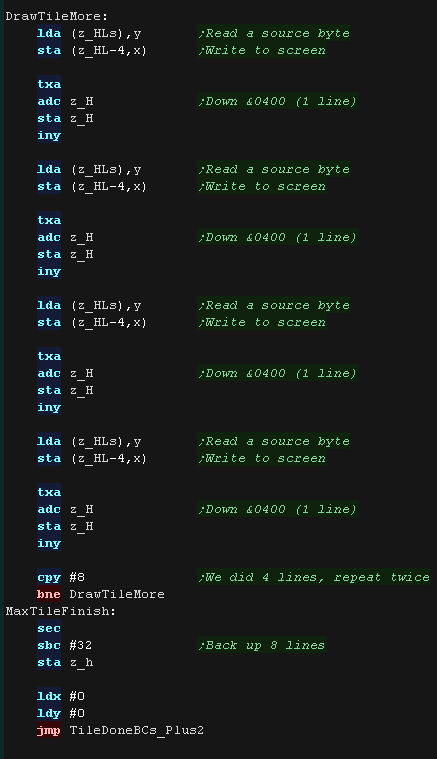
| We now use a huge 'unwrapped loop to move each line
of our source pattern to the screen. provided we're drawing to a vertically align As all the 8 bytes of our 8x8 tile are consecutive bytes we just use Y as an offset for our source pattern (z_HLs) and write to destination (z_HL), as we know X=4., we use (z_HL-4,x) as our destination after each line we add 4 (via X) to z_H t move to the next vertical line. Note: the XY bits of the pattern number are unused in this case (They define flip mode if the Program bit was set)... These could be used for a 'Tile Tint' (for 4 color patterns on 16 color systems) or a bank number (for bankswitching huge tile sets) |
 |
| If the Program bit was 1, then either we need to
flip, or run some 'custom code' Next we check the XY bits, if both are 0 this is not a flip (Transparent, Filled, Double etc) If either bit (or both) is 1, then this is some kind of flip, so we calculate the pattern source address, and move it into the z_HLs |
 |
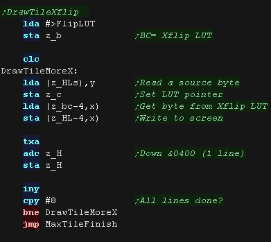
| If the Y flip bit is 0 we must be X flipping! We load each source pattern byte from z_HSs, then Xflip it via the Lookup table (in z_BC) We then write these to the screen in the same way as the unflipped data. To save coding length, we don't use an unwrapped loop this time. |
 |
| If the Y flip bit was set we now check if the X
flip bit is also set. If it's not we're just Yflipping! To flip vertically we load the source pattern data normally, but we write it to the screen from the bottom of the tile upwards. |
 |
| if the X bit was set as well as Y we need to XY
flip. We do this with a combination of both 'tricks' We use the LUT to X flip, and draw to the screen Bottom to Top to Y flip! |
 |
MaxTile Custom Draw Types
| Bits 1,2,3... XYP=%001 defines a custom program When a custom program is being used Bits 4,5 define the program type (rather than part of the low tile number) %00=Filled Tile %01=Double height tile %10=unused %11=Transparent tile/empty tile The remaining two bits 6,7 act as the High part of the tile number %------NN nnnnnnnn |
|
| A double height
tile uses only 4 lines of a pattern, so we multiply the pattern
number by 4 We then draw each line of the pattern twice to the screen. |
 |
| The fill tile is
the simplest! We use 2 bytes from the pattern data, and fill each line with one of the two We use z_E for one line, then z_D for one line - this allows us to make a nice 'checkerboard' patterned fill, or alternate lines in different colors. As so little data is read, This routine is the fastest, so should be used for as much as possible of our tilemap! |
 |
| The final type is the Transparent
tile. if the Tilenumber=255 then this tile is completely transparent, and no data will be drawn |
|
| Our transparency is a crude '0 byte' transparency. Basically, any byte equal to 0 is not drawn to the screen, others are drawn normally. We use the same pattern data as usual, but as we read in each byte, we only draw it to the screen if it isn't zero.. |
 |
 |
Lesson
P79 - MaxTile software tilemap on the Lynx Lets take a look at the advanced 'Maxtile' tilemap on the Atari Lynx , it supports Xflip,Yflip, Fastfill and more! |
|
LNX_V1_MaxTile_Normal.asm
|
|
MaxTile Definitions
| Due to the LYNX screen, the display is 26x17 tiles... unlike the other systems, the tiles are only 6x6 (not 8x8)... this gives a screen resolution of 156x102 pixels |  |
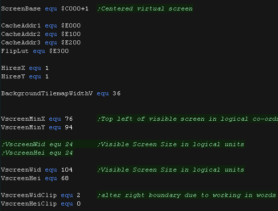
| Maxtile Caches draws to the screen in 3 thirds to reduce
flicker. We use some spare memory for the 3 draw caches (each 256 bytes) we also use 256 bytes for the 'Xflip lookup table' The VRAM base of the screen is &C000. |
 |
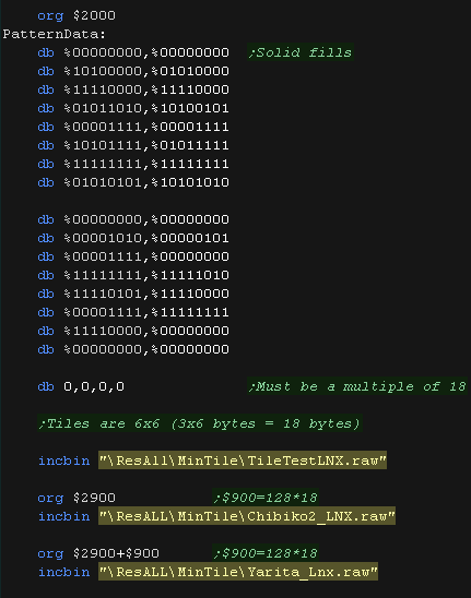
| Here is the Tile pattern data Lynx tile patterns are 6x6 pixels , with each byte containing 2 pixels... this means each tile is a rather odd 18 bytes! 'Fill tiles' are a special case, they fill a tile with 2 bytes (saving time and memory) |
 |
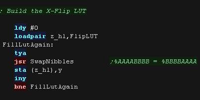
| We'll calculate an Xflip
LUT We swap the pixels in each byte, storing the flipped equivalent in the LUT This saves memory compared to storing alternative patterns. Yflip does not require a lookup table, we instead move UP VRAM instead of DOWN as we draw the pattern! |
 |
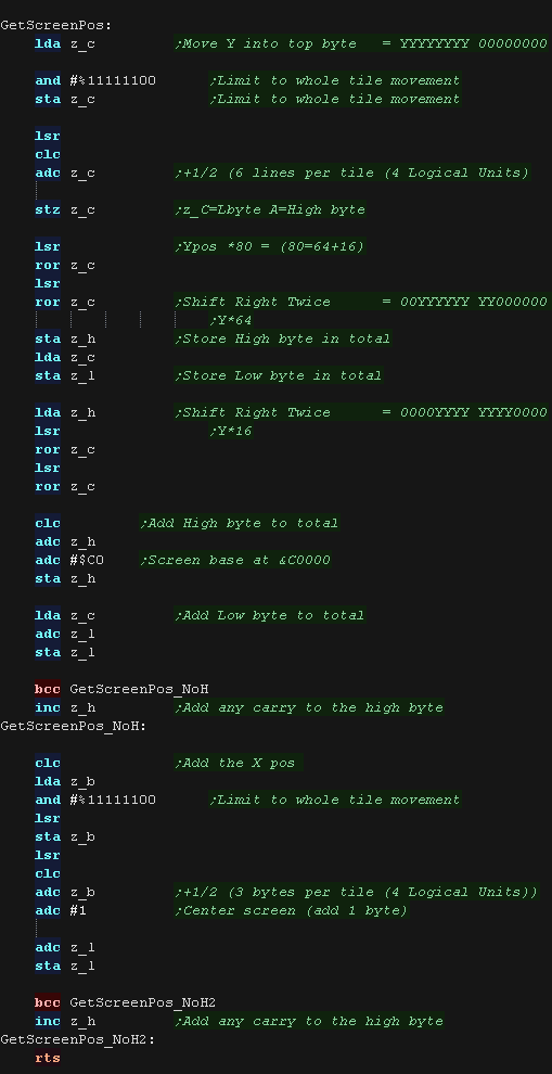
| When we want to draw a sprite object to the screen, we need to calculate the VRAM destination. MaxTile uses X,Y co-ordinates in 'Logical Units' (Pairs of pixels) - this is passed in z_BC, and the Vram destination is returned in z_HL The Lynx screen base is at address $C000. On the Lynx the Vram calculation is $C000 + YposInLines * 80 + Xpos in bytes |
 |
Tile Drawing!
| The calling
routine that exexutes DrawTile will set X and Y to zero, so we
can rely on this being the case at the start of the routine...
however we need to ensure that X and Y still contain zero by the
end of our routine |
|
| The DrawTile Routine is called by the shared code, This shared
code will backup and restore the stack pointer and load the first
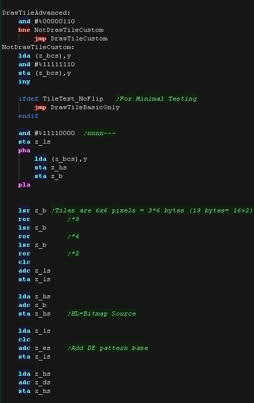
byte of the 16 bit tile number into A The low bit is shifted out (the update bit)... we need to reset it to 0 anyway! The following zero page entries are loaded: z_BCs = Tilemap z_DEs = Tile Bitmap Pattern data z_HL = VRAM Destination |
|
| To optimize things, the tile drawing works as a 'binary tree',
deciding the kind of tile drawing routine to use The Platform specific draw routine DrawTile starts by ckecking Bit 1 (now Bit 0) This is the 'Program' flag - If this is 0, then this is the simplest unflipped tile, otherwise we switch to the advanced routine. If we're drawing a basic tile, we shift a 0 back into A, and write it back, that clears the Update flag, as we will draw the tile now. We load X with 4, this speeds up our 'Downline commands' |
|
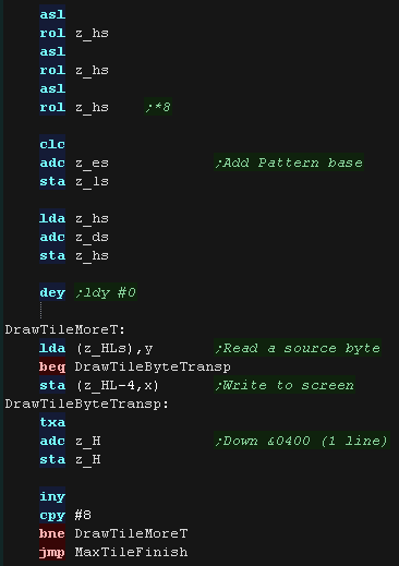
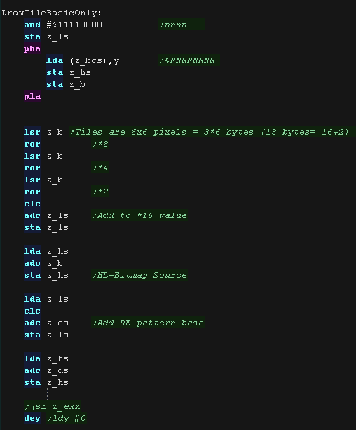
| We're going to draw a basic unflipped
tile We need to load the second byte of the tilenumber. Max tile was designed to multiply the tilenumber by 16, by using the top 12 bits of the two byte tile value, but we need to multiply by 18, so we bitshift the value into the *2 position, and add the *2 and *16 values to get *18 We add this to z_DE (the pattern data) This gives us the source address - which we load into z_HL |
 |
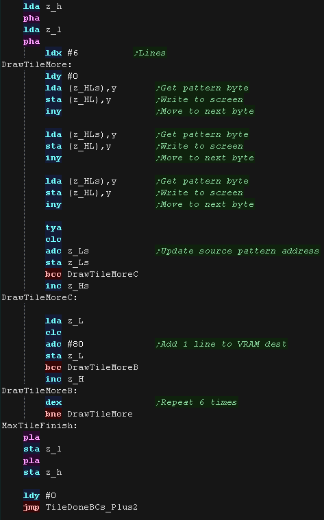
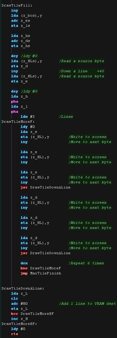
| We need to write 3 bytes for each line, after each line we add 80 to the VRAM destination to move down to the next line, We repeat for each 6 lines of our tile. |
 |
| If the Program bit was 1, then either we need to
flip, or run some 'custom code' Next we check the XY bits, if both are 0 this is not a flip (Transparent, Filled, Double etc) If either bit (or both) is 1, then this is some kind of flip, so we calculate the pattern source address, and move it into the z_HLs |
 |
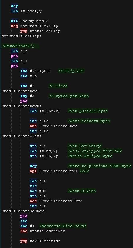
| If the Y flip bit is 0 we must be X flipping! We load each source pattern byte from z_HSs, then Xflip it via the Lookup table (in z_BC) We then write these to the screen in the same way as the unflipped data. To save coding length, we don't use an unwrapped loop this time. |
 |
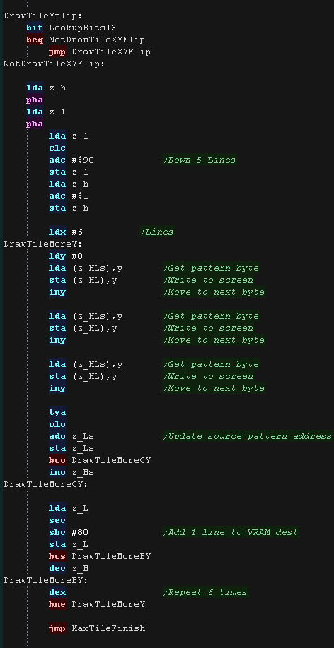
| If the Y flip bit was set we now check if the X
flip bit is also set. If it's not we're just Yflipping! To flip vertically we load the source pattern data normally, but we write it to the screen from the bottom of the tile upwards - we do this by adding $190 (80*5) to move to the last line of the source pattern. |
 |
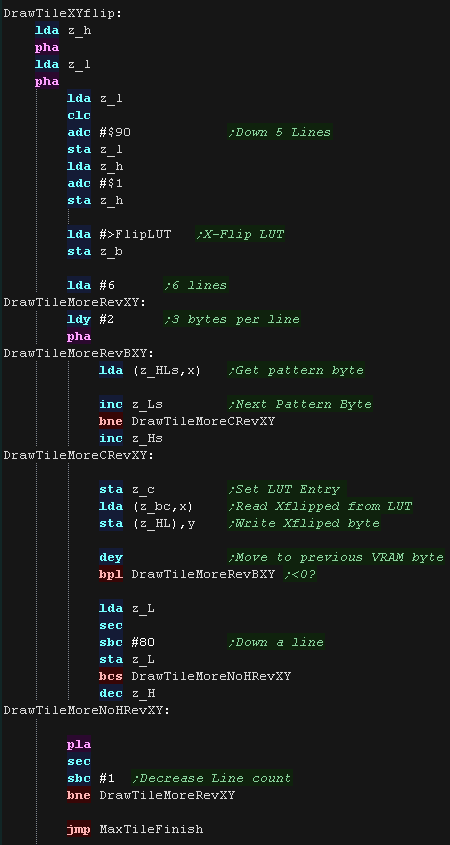
| if the X bit was set as well as Y we need to XY
flip. We do this with a combination of both 'tricks' We use the LUT to X flip, and draw to the screen Bottom to Top to Y flip! |
 |
MaxTile Custom Draw Types
| Bits 1,2,3... XYP=%001 defines a custom program When a custom program is being used Bits 4,5 define the program type (rather than part of the low tile number) %00=Filled Tile %01=Double height tile %10=unused %11=Transparent tile/empty tile The remaining two bits 6,7 act as the High part of the tile number %------NN nnnnnnnn |
|
| A double height
tile uses only 4 lines of a pattern, so we multiply the pattern
number by 9 (half our 18 byte tile) We then draw each line of the pattern twice to the screen. |
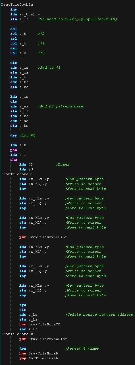 |
| The fill tile is
the simplest! We use 2 bytes from the pattern data, and fill each line with one of the two We use z_E for one line, then z_D for one line - this allows us to make a nice 'checkerboard' patterned fill, or alternate lines in different colors. As so little data is read, This routine is the fastest, so should be used for as much as possible of our tilemap! |
 |
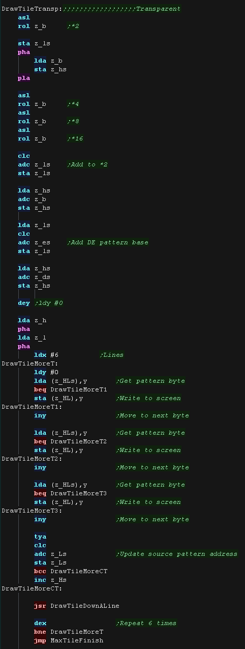
| The final type is the Transparent
tile. if the Tilenumber=255 then this tile is completely transparent, and no data will be drawn |
|
| Our transparency is a crude '0 byte' transparency. Basically, any byte equal to 0 is not drawn to the screen, others are drawn normally. We use the same pattern data as usual, but as we read in each byte, we only draw it to the screen if it isn't zero.. |
 |
| View Options |
| Default Dark |
| Simple (Hide this menu) |
| Print Mode (white background) |
| Top Menu |
| ***Main Menu*** |
| Youtube channel |
| Patreon |
| Introduction to Assembly (Basics for absolute beginners) |
| Amazon Affiliate Link |
| AkuSprite Editor |
| ChibiTracker |
| Dec/Bin/Hex/Oct/Ascii Table |
| Alt Tech |
| Archive.org |
| Bitchute |
| Odysee |
| Rumble |
| DailyMotion |
| Please note: I wlll upload more content to these alt platforms based on the views they bring in |
| 68000 Content |
| ***68000 Tutorial List*** |
Learn 68000 Assembly  |
| Hello World Series |
| Platform Specific Series |
| Simple Samples |
| Grime 68000 |
| 68000 Downloads |
| 68000 Cheatsheet |
| Sources.7z |
| DevTools kit |
| 68000 Platforms |
| Amiga 500 |
| Atari ST |
| Neo Geo |
| Sega Genesis / Mega Drive |
| Sinclair QL |
| X68000 (Sharp x68k) |
| 8086 Content |
| Learn 8086 Assembly |
| Platform Specific Series |
| Hello World Series |
| Simple Samples |
| 8086 Downloads |
| 8086 Cheatsheet |
| Sources.7z |
| DevTools kit |
| 8086 Platforms |
| Wonderswan |
| MsDos |
| ARM Content |
| Learn ARM Assembly |
| Learn ARM Thumb Assembly |
| Platform Specific Series |
| Hello World |
| Simple Samples |
| ARM Downloads |
| ARM Cheatsheet |
| Sources.7z |
| DevTools kit |
| ARM Platforms |
| Gameboy Advance |
| Nintendo DS |
| Risc Os |
| Risc-V Content |
| Learn Risc-V Assembly |
| Risc-V Downloads |
| Risc-V Cheatsheet |
| Sources.7z |
| DevTools kit |
| MIPS Content |
| Learn Risc-V Assembly |
| Platform Specific Series |
| Hello World |
| Simple Samples |
| MIPS Downloads |
| MIPS Cheatsheet |
| Sources.7z |
| DevTools kit |
| MIPS Platforms |
| Playstation |
| N64 |
| PDP-11 Content |
| Learn PDP-11 Assembly |
| Platform Specific Series |
| Simple Samples |
| PDP-11 Downloads |
| PDP-11 Cheatsheet |
| Sources.7z |
| DevTools kit |
| PDP-11 Platforms |
| PDP-11 |
| UKNC |
| TMS9900 Content |
| Learn TMS9900 Assembly |
| Platform Specific Series |
| Hello World |
| TMS9900 Downloads |
| TMS9900 Cheatsheet |
| Sources.7z |
| DevTools kit |
| TMS9900 Platforms |
| Ti 99 |
| 6809 Content |
| Learn 6809 Assembly |
| Learn 6309 Assembly |
| Platform Specific Series |
| Hello World Series |
| Simple Samples |
| 6809 Downloads |
| 6809/6309 Cheatsheet |
| Sources.7z |
| DevTools kit |
| 6809 Platforms |
| Dragon 32/Tandy Coco |
| Fujitsu FM7 |
| TRS-80 Coco 3 |
| Vectrex |
| 65816 Content |
| Learn 65816 Assembly |
| Hello World |
| Simple Samples |
| 65816 Downloads |
| 65816 Cheatsheet |
| Sources.7z |
| DevTools kit |
| 65816 Platforms |
| SNES |
| eZ80 Content |
| Learn eZ80 Assembly |
| Platform Specific Series |
| eZ80 Downloads |
| eZ80 Cheatsheet |
| Sources.7z |
| DevTools kit |
| eZ80 Platforms |
| Ti84 PCE |
| IBM370 Content |
| Learn IBM370 Assembly |
| Simple Samples |
| IBM370 Downloads |
| IBM370 Cheatsheet |
| Sources.7z |
| DevTools kit |
| Super-H Content |
| Learn SH2 Assembly |
| Hello World Series |
| Simple Samples |
| SH2 Downloads |
| SH2 Cheatsheet |
| Sources.7z |
| DevTools kit |
| SH2 Platforms |
| 32x |
| Saturn |
| PowerPC Content |
| Learn PowerPC Assembly |
| Hello World Series |
| Simple Samples |
| PowerPC Downloads |
| PowerPC Cheatsheet |
| Sources.7z |
| DevTools kit |
| PowerPC Platforms |
| Gamecube |
| Work in Progress |
| ChibiAndroids |
| Misc bits |
| Ruby programming |
Buy my Assembly programming book
on Amazon in Print or Kindle!


Available worldwide!
Search 'ChibiAkumas' on
your local Amazon website!
Click here for more info!


Buy my Assembly programming book
on Amazon in Print or Kindle!
Available worldwide!
Search 'ChibiAkumas' on
your local Amazon website!
Click here for more info!
Buy my Assembly programming book
on Amazon in Print or Kindle!
Available worldwide!
Search 'ChibiAkumas' on
your local Amazon website!
Click here for more info!
Buy my Assembly programming book
on Amazon in Print or Kindle!
Available worldwide!
Search 'ChibiAkumas' on
your local Amazon website!
Click here for more info!
Buy my Assembly programming book
on Amazon in Print or Kindle!
Available worldwide!
Search 'ChibiAkumas' on
your local Amazon website!
Click here for more info!
Buy my Assembly programming book
on Amazon in Print or Kindle!
Available worldwide!
Search 'ChibiAkumas' on
your local Amazon website!
Click here for more info!
Buy my Assembly programming book
on Amazon in Print or Kindle!
Available worldwide!
Search 'ChibiAkumas' on
your local Amazon website!
Click here for more info!
Buy my Assembly programming book
on Amazon in Print or Kindle!
Available worldwide!
Search 'ChibiAkumas' on
your local Amazon website!
Click here for more info!
Buy my Assembly programming book
on Amazon in Print or Kindle!
Available worldwide!
Search 'ChibiAkumas' on
your local Amazon website!
Click here for more info!
Buy my Assembly programming book
on Amazon in Print or Kindle!
Available worldwide!
Search 'ChibiAkumas' on
your local Amazon website!
Click here for more info!
Buy my Assembly programming book
on Amazon in Print or Kindle!
Available worldwide!
Search 'ChibiAkumas' on
your local Amazon website!
Click here for more info!