| Mnemonic |
Description |
Example |
Addressing
Modes |
Flags |
| ADC <ea> |
Add <ea> and the carry flag to the Accumulator
A. |
ADC #61 |
Imm ; ZeroPg ; ZeroPg,X ; Abs ; Abs,X ; Abs,Y ; (ind)
{65c02}; (Ind,X), (Ind),Y |
N Z C - - V |
| AND <ea> |
Logical AND of bits in 8 bit value <ea> with
Accumulator |
AND $12 |
Accum ; ZeroPg ; ZeroPg,X ; Abs ; Abs,X |
N Z C - - - |
| ASL <ea> |
Shift <ea> Left for Arithmetic. |
ASL |
Accum ; ZeroPg ; ZeroPg,X ; Abs ; Abs,X |
- - - - - - |
| Bcc ofst |
Branch to the 8 bit offset ofst IF condition cc is
true. |
BEQ TestLabel |
|
- - - - - - |
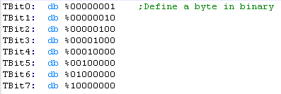
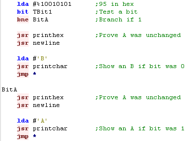
| BIT <ea> |
Test bits in Accumulator compared to <ea> |
BIT $61 |
Imm {65c02} ; ZeroPg ; ZeroPg,X {65c02} ; Abs ; Abs,X
{65c02} |
N Z - - - V |
| BRK |
Stop the CPU and execute an interrupt. |
BRK |
|
- - - I - - |
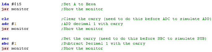
| CLC |
Clear the Carry Flag. C flag will be set to Zero. |
CLC |
|
- - C - - - |
| CLD |
Clear the Decimal Flag. (BCD off) |
CLD |
|
- - - - D - |
| CLI |
Clear the Interrupt Flag. (Enable Interrupts) |
CLI |
|
- - - I - - |
| CLV |
Clear the oVerflow Flag. V flag will be set to Zero. |
CLV |
|
- - - - - V |
| CMP <ea> |
Compare the Accumulator to <ea>. |
CMP #10 |
Imm ; ZeroPg ; ZeroPg,X ; Abs ; Abs,X ; Abs,Y ; (ind)
{65c02} ; (Ind,X), (Ind),Y |
N Z C - - - |
| CPX <ea> |
Compare the X register to <ea>. |
CPX #10 |
Imm ; ZeroPg ; Abs |
N Z C - - - |
| CPY <ea> |
Compare the Y register to <ea>. |
CPY #10 |
Imm ; ZeroPg ; Abs |
N Z C - - |
| DEC <ea> |
Decrease the 8 bit value <ea> by one. |
DEC $10 |
Accum {65c02}; ZeroPg ; ZeroPg,X ; Abs ; Abs,X |
N Z - - - - |
| DEX |
Decrease register X by one. |
DEX |
|
N Z - - - - |
| DEY |
Decrease register Y by one. |
DEY |
|
N Z - - - - |
| EOR <ea> |
Logical EOR (Exclusive OR) of bits in <ea> with
A |
EOR <ea> |
Imp ; ZeroPg ; ZeroPg,X ; Abs ; Abs,X ; Abs,Y ; (ind)
{65c02} ; (Ind,X), (Ind),Y |
N Z - - - - |
| INC <ea> |
Increase the 8 bit value <ea> by one. |
INC $10 |
Accum {65c02}; ZeroPg ; ZeroPg,X ; Abs ; Abs,X |
N Z - - - - |
| INX |
Increase register X by one. |
INX |
|
N Z - - - - |
| INY |
Increase register Y by one. |
INY |
|
N Z - - - - |
| JMP addr |
Jump to the 16 bit address addr. |
JMP $4000 |
Abs ; (Ind Abs,X) {65c02} ; (Ind) |
- - - - - - |
| JSR addr |
Jump to Subroutine at address addr. |
JSR addr |
Abs |
- - - - - - |
| LDA <ea> |
Load the 8 bit value from <ea> into the
Accumulator. |
LDA #100 |
Imm ; ZeroPg ; ZeroPg,X ; Abs ; Abs,X ; Abs,Y ;
(ind) {65c02} ; (Ind,X), (Ind),Y |
N Z - - - - |
| LDX <ea> |
Load the 8 bit value from <ea> into the X
register. |
LDX #100 |
Imm ; ZeroPg ZeroPg,Y ; Abs ; Abs,Y |
N Z - - - - |
| LDY <ea> |
Load the 8 bit value from <ea> into the Y
register. |
LDY #100 |
Imm ; ZeroPg ZeroPg,X ; Abs ; Abs,X |
N Z - - - - |
| LSR <ea> |
Shift the bits of <ea> Right Logically. |
LSR $1000 |
Accum ; ZeroPg ; ZeroPg,X ; Abs ; Abs,X |
N Z C - - - |
| NOP |
No Operation. |
NOP |
|
- - - - - - |
| ORA <ea> |
Logical OR of bits in 8 bit value <ea> with
Accumulator |
ORA #61 |
Imm ; ZeroPg ; ZeroPg,X ; Abs ; Abs,X ; Abs,Y ; (ind)
{65c02}; (Ind,X), (Ind),Y |
N Z C - - V |
| PHA |
Push a byte from register A onto the top of the
stack. |
PHA |
|
- - - - - - |
| PHP |
Push the flags (P) onto the stack. |
PHP |
|
- - - - - - |
| PLA |
Pull a byte off the stack into register A. |
PLA |
|
- - - - - - |
| PLP |
Pull a byte off the stack into register A. |
PLP |
|
N Z C I D V |
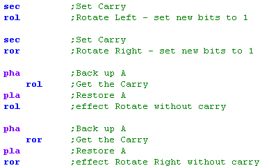
| ROL <ea> |
Rotate bits of <ea> Left with the Carry. |
ROL $40 |
Accum ; ZeroPg ; ZeroPg,X ; Abs ; Abs,X |
N Z C - - - |
| ROR <ea> |
Rotate bits of <ea> Right with the Carry. |
ROR $40 |
Accum ; ZeroPg ; ZeroPg,X ; Abs ; Abs,X |
N Z C - - - |
| RTI |
Return from an interrupt. |
RTI |
|
N Z C I D V |
| RTS |
Return from a subroutine. |
RTS |
|
- - - - - - |
| SBC <ea> |
Subtract <ea> and the carry flag from the
Accumulator |
SBC #61 |
Imm ; ZeroPg ; ZeroPg,X ; Abs ; Abs,X ; Abs,Y ; (ind)
{65c02}; (Ind,X), (Ind),Y |
N Z C - - V |
| SEC |
Set the carry flag to 1. |
SEC |
|
- - C - - - |
| SED |
Set the Decimal Flag. (BCD on) |
SED |
|
- - - - D - |
| SEI |
Set the Interrupt Flag. |
SEI |
|
- - - I - - |
| STA <ea> |
Store the Accumulator into memory address <ea>. |
STA $10 |
ZeroPg ; ZeroPg,X ; Abs ; Abs,X ; Abs,Y ; (ind)
{65c02} ; (Ind,X), (Ind),Y |
- - - - - - |
| STX <ea> |
Store the X register into memory address <ea>. |
STX $10 |
ZeroPg ; ZeroPg,Y ; Abs |
- - - - - - |
| STY <ea> |
Store the Y register into memory address <ea>. |
STY $10 |
ZeroPg ; ZeroPg,X ; Abs |
- - - - - - |
| TAX |
Transfer the Accumulator into register X. |
TAX |
|
N Z - - - - |
| TAY |
Transfer the Accumulator into register Y. |
TAY |
|
N Z - - - - |
| TSX |
Transfer the Stack pointer into register X. |
TSX |
|
N Z - - - - |
| TXA |
Transfer the X register into the Accumulator. |
TXA |
|
N Z - - - - |
| TXS |
Transfer the X Register into the Stack pointer. |
TXS |
|
- - - - - - |
| TYA |
Transfer the Y register into the Accumulator. |
TYA |
|
N Z - - - - |