

Platform Specific Lessons

Sfx with Chibisound!
| These tutorials use a sound 'driver' called ChibiSound, Chibisound uses a single byte parameter in D0, and provides 64 different pitches, in low or high volume with either tones or noise. Sending a value of 0 mutes sound, all other values make a tone... Chibisound is intended to make it simple to have SFX in multiplatform games and was used in Grime Z80 and Grime 68000 |
|
| In this example
we're using channel 2 for our sound, that's because the register
numbers match the first channel of the NeoGeo FM chip, as the two
are compatibile. |
 |
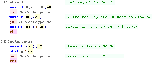
Writing Chibisound
| Before we do any writing to the FM chip, we need to check if the
sound chip isn't busy, to do this we read in from $A04000, and wait
for bit 7 to be zero When we want to set a register on the YM2612 sound chip, we first write the register we want to change to $A04000, next we write the new value for the register to $A04001 The register will now be changed. |
 |
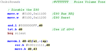
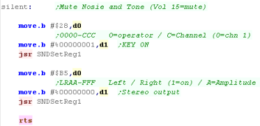
| So, Lets start writing Chibisound! First we need to turn of the Z80, so we have access to the sound chip... to do this we write $100 to $A11100 and $A11200, this turns off the Z80, and gives us full access to the sound resources... Now we're going to check if the parameter passed (in D0) was zero, if it was, then we need to silence the sound chip.... if not, we back up D0 into D3 To silence the sound chip, we release all the keys of Channel 2 using Reg $28... we also set the channel to map to neither speaker with Reg $B5, stopping sound output (we use Channel 2 for compatibility with the NeoGeo FM Chip) |
  |
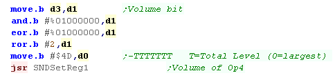
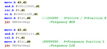
| Our definition only has 1 bit (bit 6), we're going to shift it two
bits to the right, so our 'High' and 'Low' volume are balanced... On YM2612 Zero is loudest, and 127 is quiet, so we have to flip the bit in D1, before writing to register $4D |
 |
| We've set our volume, next we need to set the pitch of the sound
channel, We need to use Reg $A5 (the high part) and $A1 (the low part) to set the pitch... the Chibisound definition uses 6 bits, so we split them up, and send 2 of the bits to $A4, and 4 to $A1 |
 |
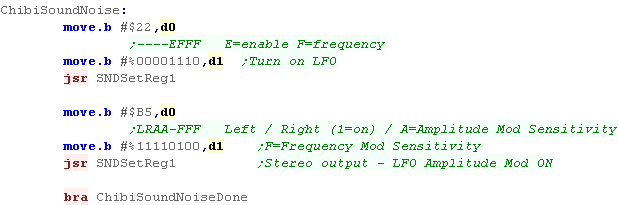
| Next we're going to test the noise bit (bit 7) if it's set, we're going to use the LFO to distort the sound. | 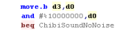 |
| * When the noise is set* To turn on the LFO, we need to set bit 4 of Reg $22, we also want to set the frequency with bits 0-2 We need to set the LFO to affect the Amplitude and frequency with bits 0-5 of reg $B5 - we also set bits 6&7 - which set the channel to a mono channel - coming out of both speakers |
 |
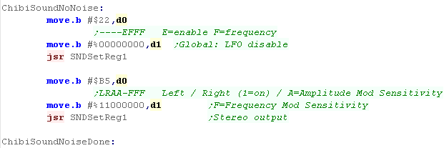
| * When the noise isn't set* If we're not making a noise, we need to clear the bits of Reg $22, We still need to set the top two bits of reg $B5 - as these allow the Channel to play |
 |
| We've set all the parameters that change, but we needs to set some
defaults... We're going to set an 'algorithm' - each channel has 4 'operations', and the algorithm defines how these change the sound... as we're only enabling Op4 we're just using Algorithm 0 - which will just make a simple tone Next we need to set the 'Multiplier' - changing the multiplier will alter the pitch - we'll set it to 1 We need to define the way our tone sounds over time next We're going to set the minumum Attarck rate ($5D) - this makes our tone reach maximum as fast as possible We need to set the top bit of $6D to ensure the LFO will work (when it's on - it has no effect if off), we also set the Decay rate We'll also set the maximum sustain and release rate ($8D) we want our note to be basically constant |
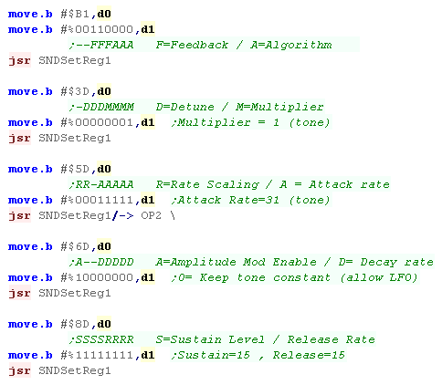 |
| Finally we want to turn on our sound... we've programmed Op4 of Channel 2 - so we need to set bits 0 and 7 to 1 in reg &28 to make the tone play. | 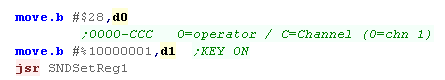 |
| Using the 68000 for simple sounds it easy, but for
music we probably want to use the Z80... Remember, the Genesis sound chip is backwards compatible with the Sega Master System, so we can even use a SMS music player on the Genesis. |
 |

Sfx with Chibisound!
| These tutorials use a sound 'driver' called ChibiSound, Chibisound uses a single byte parameter in D0, and provides 64 different pitches, in low or high volume with either tones or noise. Sending a value of 0 mutes sound, all other values make a tone... Chibisound is intended to make it simple to have SFX in multiplatform games and was used in Grime Z80 and Grime 68000 |
|
Writing Chibisound!
| We're going to use a pair of 'templates' of bytes - depending on
the sound we want to make, we'll use one or the other of these
two... we'll then 'patch in' the settings for the pitch and noise as
required, When we actually call the sound trap, we need to pass a pointer to this data. |
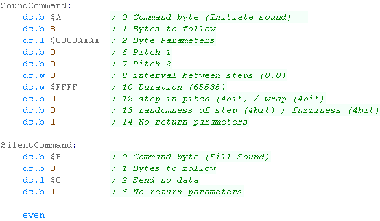 |
| First we're going to check if the parameter passed was zero, if it is, then we load the 'Silent' command address into A3, and pass this to trap #1, command #$11 | 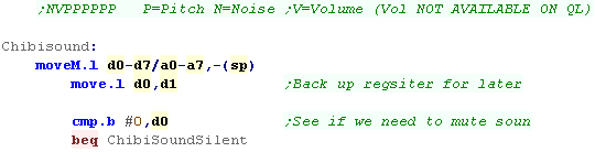  |
| If the sound isn't silent, we're going to patch new settings into
the 'soundcommand' data - so we load the address into a3 then we need to set the pitch... we have 6 pitch bits, so we load these into 'Pitch 1' - 6 bytes into 'soundcommand' |
 |
| We're going to handle the noise... if we're making a noise sound, we want to write $CC to byte 13 of the definition... if the noise is off, we want to write $00 to byte 13. |  |
| The QL isn't capable of volumes, so we're ignoring the volume bit! | this space blank! |
| Finally we send the data!... we use Trap #1, command #$11 (in D0)... the pointer to the command needs to be in A3, but we did this earlier. |  |
 |
The
Sinclair QL sound is pretty limited, but at least we can make a
few simple beeps for our games. It seems there's no way, however, to change the volume of the sound. |
| Not all Sinclair QL emulators support sound, QLay2, for example does not support sound, so don't sit around wondering why your code doesn't work if your emulator doesn't actually support it! |  |

Sound ports on the Amiga
|
We need to use the Chip registers to control the sound, but unlike with the graphics, we're not going to use the Copper Chip. When we specify the address of the sample, we need this to be in Chip ram (Defined with 'Section ChipRAM,Data_c' |
 |
| Name | Address $DFFnnn |
Function | Bits | Details |
| DMACON | 096 | DMA control write (clear or set) | S-----E- ---DCBA | S=Set/Clr E=enable ABCD=Channnels |
| AUD0LCH | 0A0 | Audio channel 0 (L) location (high 3 bits, 5 if ECS) | -------- ---hhHHH | Address H � Must be within CHIP ram! |
| AUD0LCL | 0A2 | Audio channel 0 (L) location (low 15 bits) | LLLLLLLL LLLLLLL- | Address L � Must be within CHIP ram! |
| AUD0LEN | 0A4 | Audio channel 0 (L) length | DDDDDDDD DDDDDDDD | Data Length |
| AUD0PER | 0A6 | Audio channel 0 (L) period | PPPPPPPP PPPPPPPP | Period |
| AUD0VOL | 0A8 | Audio channel 0 (L) volume | -------- --VVVVVV | V=Volume (64=max) |
| AUD0DAT | 0AA | Audio channel 0 (L) data | DDDDDDDD DDDDDDDD | Data |
| AUD1LCH | 0B0 | Audio channel 1 (R) location (high 3 bits) | -------- ---hhHHH | Address H � Must be within CHIP ram! |
| AUD1LCL | 0B2 | Audio channel 1 (R) location (low 15 bits) | LLLLLLLL LLLLLLL- | Address L � Must be within CHIP ram! |
| AUD1LEN | 0B4 | Audio channel 1 (R) length | DDDDDDDD DDDDDDDD | Data Length |
| AUD1PER | 0B6 | Audio channel 1 (R) period | PPPPPPPP PPPPPPPP | Period |
| AUD1VOL | 0B8 | Audio channel 1 (R) volume | -------- --VVVVVV | V=Volume (64=max) |
| AUD1DAT | 0BA | Audio channel 1 (R) data | DDDDDDDD DDDDDDDD | Data |
| AUD2LCH | 0C0 | Audio channel 2 (L) location (high 3 bits) | -------- ---hhHHH | Address H � Must be within CHIP ram! |
| AUD2LCL | 0C2 | Audio channel 2 (L) location (low 15 bits) | LLLLLLLL LLLLLLL- | Address L � Must be within CHIP ram! |
| AUD2LEN | 0C4 | Audio channel 2 (L) length | DDDDDDDD DDDDDDDD | Data Length |
| AUD2PER | 0C6 | Audio channel 2 (L) period | PPPPPPPP PPPPPPPP | Period |
| AUD2VOL | 0C8 | Audio channel 2 (L) volume | -------- --VVVVVV | V=Volume (64=max) |
| AUD2DAT | 0CA | Audio channel 2 (L) data | DDDDDDDD DDDDDDDD | Data |
| AUD3LCH | 0D0 | Audio channel 3 (R) location (high 3 bits) | -------- ---hhHHH | Address H � Must be within CHIP ram! |
| AUD3LCL | 0D2 | Audio channel 3 (R) location (low 15 bits) | LLLLLLLL LLLLLLL- | Address L � Must be within CHIP ram! |
| AUD3LEN | 0D4 | Audio channel 3 (R) length | DDDDDDDD DDDDDDDD | Data Length |
| AUD3PER | 0D6 | Audio channel 3 (R) period | PPPPPPPP PPPPPPPP | Period |
| AUD3VOL | 0D8 | Audio channel 3 (R) volume | -------- --VVVVVV | V=Volume (64=max) |
| AUD3DAT | 0DA | Audio channel 3 (R) data | DDDDDDDD DDDDDDDD | Data |
 |
We're going to
use Channel 0 and Channel 1 to make a 'mono sound... As each channel is 16 bytes apart, we can specify the registers of Channel1 as Channel0's +16 - Eg: DFF0A2+16 for DFF0B2 This will make it easier to see we're changing the equivalent setting of Channel 1 when we set both together. |
Sfx with Chibisound!
| These tutorials use a sound 'driver' called ChibiSound, Chibisound uses a single byte parameter in D0, and provides 64 different pitches, in low or high volume with either tones or noise. Sending a value of 0 mutes sound, all other values make a tone... Chibisound is intended to make it simple to have SFX in multiplatform games and was used in Grime Z80 and Grime 68000 |
|
Writing Chibisound!
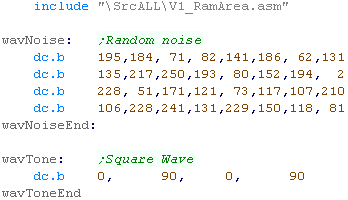
| To make tones on the Amiga, we need to define some sound data in
Chip ram. We're going to define two sound samples, one for square wave tones... and one for noise. |
 |
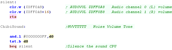
| Chibisound uses the register D0 as the byte parameter, When ChibiSound Starts, we need to check if it contains a 0... if it is we're going to silence the sound... We do this by writing zero to Channels 0 and 1's volume at $DFF0A8 and $DFF0B8 ($DFF0A8+16) Since channel 1's data is 16 bytes after Channel 0, we can +16 the address of the Channel 0 ports to get the equivalent port on Channel 1 |
 |
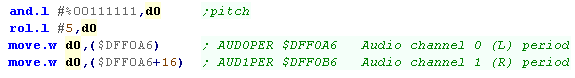
| First we're going to set the pitch... we have 6 pitch bits in our
Chibisound Definition. The 'Period' Setting on the Amiga will change the pitch, but this takes 16 bits... we rotate our 6 bits left 5 bits, to make a good mid tone for our sound. Because we want a Mono tone, we set Channel 0 (Left) and Channel 1's (Right) period together to this new value. |
 |
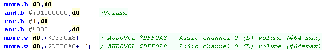
| We're going to set the volume next... on the Amiga, the maximum
volume is 64... We've only got one Volume bit in the ChibiSound definition, if it's set we'll use a volume of 63, if it's clear, we'll use a volume of 31 |
 |
| We're going to either play the noise sample, or the tone sample
depending on bit 7... We load the address (in chip ram) into A0... we load the sample length in A1 We also run a function called 'ChibiSoundNoise'... this will alter the bytes in wavNoise to change them - making the sound more random and distorted. |
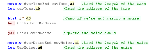 |
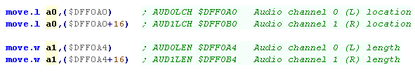
| We're going to load the 'Location' registers at $DFF0A0 and
$DFF0B0 with A0 We're going to load the length into $DFF0A4 and $DFF0B4 with A1 |
 |
| We need to turn on the sound DMA... we need to enable channels 0 and 1 to make the Amiga feed sound from the wav to the speakers. | 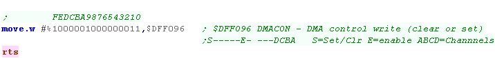 |
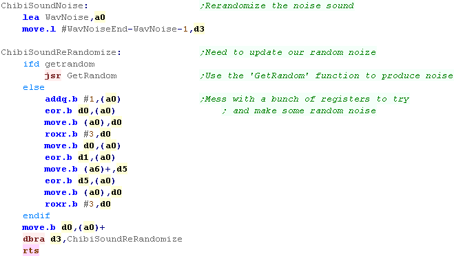
Randomizing the noise
| To make the random sound more distorted we need to keep changing
the noise data, If we have a 'DoRandom' function defined by our program, we'll use that... if not we'll just EOR a bunch of the registers together to effect some randomness. |
 |
|
This
randomizing function is OKish, but really we want to run it more
often - we run it during Vblank (60 times a second) for better
noise - We can also make the noise sample longer, if we can spare
the memory. |
Sprite Settings
Each Sprite has 4 Words defining the settings of the sprite... these start at $EB0000 for sprite 0.... $EB0008 for sprite 1, through to $EB03F8 for sprite 127
| Address | F | E | D | C | B | A | 9 | 8 | 7 | 6 | 5 | 4 | 3 | 2 | 1 | 0 | ||
| $EB0000 | - | - | - | - | - | - | X | X | X | X | X | X | X | X | X | X | X=Xpos | |
| $EB0002 | - | - | - | - | - | - | Y | Y | Y | Y | Y | Y | Y | Y | Y | Y | Y=Ypos | |
| $EB0004 | V | H | - | - | C | C | C | C | S | S | S | S | S | S | S | S | V=Vflip, H=Hflip, C=color, S=sprite | |
| $EB0006 | - | - | - | - | - | - | - | - | - | - | - | - | - | - | P | P | P=Priority (00=off... 01=back... 11=front) |
Sprite Bitmap Data Settings
Sprite bitmap data appears from address $EB8000 onwards, each sprite is 128 bytes...
Sprites are split into four 8x8 chunks, these are stored in 4 different memory addresses to make up the 16x16 sprite, The byte data for these sprites uses 1 nibble for each pixel, and selects a color from the chosen palette for that pixel
Sprite Pixel Data:
8x8 Chunk layout:
|
8x8 chunks position in ram:
|
|||||||||||||||||||||||||||||||||||||||||||||||||||||||||||||||||||||||||||||||||||||||||||||||||||||||||||||||||||||||||||||||||
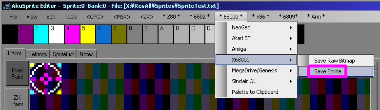
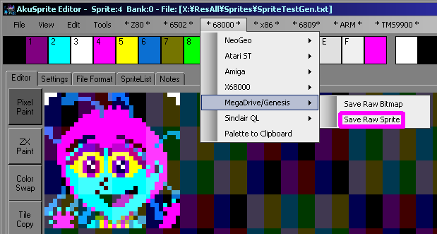
| My AkuSprite Editor can export valid x68000 sprite data, It's free and opensource (C#) and supports all the systems covered by my tutorials. |
 |
|||||||||||||||||||||||||||||||||||||||||||||||||||||||||||||||||||||||||||||||||||||||||||||||||||||||||||||||||||||||||||||||||
Setting Graphics Modes
To setup sprites on our graphics mode we'll need to set up a viariety of
registers depending on our screenmode, Viable settings are shown below:
| High Resolution | Low Resolution | |||||||
| RegNum | 768x512 | 512x512 | 512x256 | 256x256 | 512x512 | 512x256 | 256x256 | Register Purpose |
| E80000 | $89 | $5B | $5B | $2B | $4B | $4B | $25 | R00 Horizontal total |
| E80002 | $0E | $09 | $09 | $04 | $03 | $03 | $01 | R01 Horizontal synchronization end position timing |
| E80004 | $1C | $11 | $11 | $06 | $04 | $05 | $00 | R02 Horizontal display start position |
| E80006 | $7C | $51 | $51 | $26 | $45 | $45 | $20 | R03 Horizontal display end position |
| E80008 | $237 | $237 | $237 | $237 | $103 | $103 | $103 | R04 Vertical total |
| E8000A | $05 | $05 | $05 | $05 | $02 | $02 | $02 | R05 Vertical synchronization end position timing |
| E8000C | $28 | $28 | $28 | $28 | $10 | $10 | $10 | R06 Vertical display start position |
| E8000E | $228 | $228 | $228 | $228 | $100 | $100 | $100 | R07 Vertical display end position |
| E80010 | $1B | $1B | $1B | $1B | $44 | $44 | $24 | R08 External synchronization horizontal adjust: Horizontal position tuning |
| E80028 | $05 | $01 | $00 | R20 Memory mode/Display mode control | ||||
| E80400 | $00 | $00 | $00 | R0 (Screen mode initialization) - Detail | ||||
| E80500 | $2E4 | $2E4 | $2E4 | R1 (Priority control) - Priority (Sprites foreground) | ||||
| E80600 | $C1 | $C1 | $C1 | R2 (Special priority/screen display) - Screen On / Sprites On | ||||
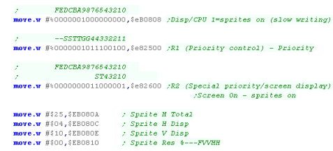
| EB0808 | $200 | $200 | $200 | $200 | $200 | $200 | $200 | BG Control (Sprites Visible, slow writing) |
| EB080A | $FF | $FF | $FF | $FF | $FF | $25 | Sprite H Total | |
| EB080C | $15 | $15 | $0A | $09 | $09 | $04 | Sprite H Disp | |
| EB080E | $28 | $28 | $28 | $10 | $10 | $10 | Sprite V Disp | |
| EB0810 | $15 | $11 | $10 | $05 | $01 | $00 | Sprite Res %---FVVHH | |
Using Sprites in our
code
| We need to set up some extra
registers to get our sprites working - otherwise they just won't
show! We have to set up our layering correctly, so the sprites are in the foreground, we do this by setting $E82500 to $2E4 We have to enable the sprite layer, we do this by setting $E82600 to $C1 We also need to set the "Background Control"... we're going to make the sprites visible, this slows down writing, but means we can change the sprites while showing them... we do this by writing $200 to $EB0808 We also need to set Registers $EB080A-$EB0810 to the values shown in the 'Setting Graphics Modes' Table |
 |
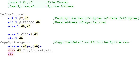
| Before we'll need to set up the bitmap data of the sprite, we'll
need to set up a source in ram, and a destination sprite pattern
number in vram. Then we just need to copy the data into sprite ram at $EB8000 |
 |
| Once our sprite data is defined, we can actually show a sprite...
We need to specify a hardware sprite number, and all the parameters of the sprite, the sprite will be shown to the screen. |
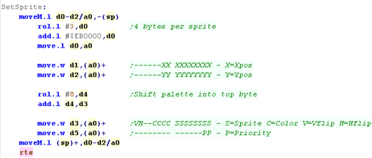 |
| We can use the code shown to the right, to show the sprite to the screen. | 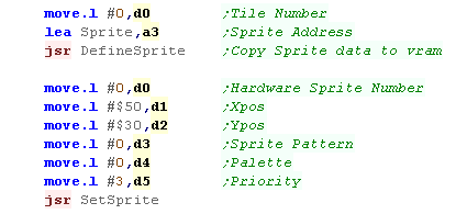 |
| The 16x16 Crosshair sprite will be shown to the screen |  |
 |
While a
relatively obscure system, The x68000's hardware is pretty
impressive compared to many 16 bits, and the sprites are no
exception - only a system like the NeoGeo can really compete with
the x68000 - and it has the difficulty of not having any bitmap
modes, or conventional Tile modes (it only has sprites). |

Hardware Sprites
| On the NeoGeo Sprites are 16 pixels
wide, and are made up of tiles 16 pixels tall... they are 16 colors
(4 bitplanes) so each tile is 128 bytes... The NeoGeo is capable of
up to 380 sprites total. A sprite can be made up of up to 32 tiles to make the sprite taller... there is also a 'Chain' bit - this will connect a sprite to the previous sprite (Sharing its position) to make a sprite wider! Hardware sprite Tiles are not in the same format as the FIX layer - they are 16x16 pixels in size and use bitplanes, but the layout is odd, and they are split onto two rom files (C1/C2 or C3/C4 etc) The sprite is split into 2x 8 pixel wide 'columns' the rightmost one is stored first - each pair of bitplanes 0 & 1 are stored together in ROM C1 - and 2 & 3 are stores in ROM C2 - all 16 lines of the right half are stored first - then the 16 lines of the left side are stored - making a total of 128 bytes (64 in each file) |
|
| You can make a valid NeoGeo Sprite file using my AkuSprite Editor... it's free and open source, and is included with the sources.7z file. | 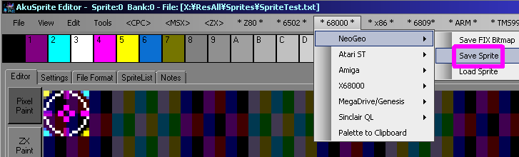 |
Sprite Roms
| If we're using MAME as our emulator, then our ROM files are mapped
into memory by the NEOGEO.XML file... the NeoGeo bios has some sprites of it's own in 202-c1.c1 and 202-c2.c2.... We'll create a second file called Sprites.c1 and Sprites.c2... with the configuration show below, our sprites will start at Pattern number $2000 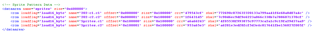 |
| If the CRC or
SHA1 are incorrect in the XML Mame will whine about it... If the filesize is wrong, MAME will CRASH!... Akusprite editor pads the file out to $100000 (by default) and there is a tool provided in these tutorial's build script to help calculate everything correctly for mame. |
|
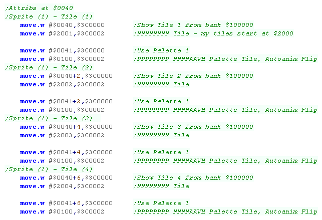
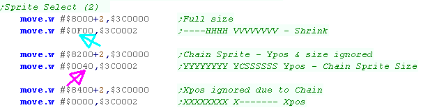
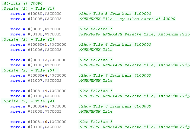
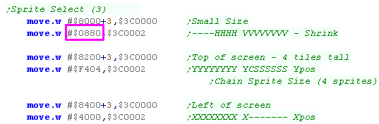
Sprite Attributes
Each sprite is defined by 1-32 tile definitions, A palette/flip byte, a Scale byte, a Ypos/Height byte and an Xpos... lets see what all these bits do in detail!Note, it's possible to scale a sprite DOWN, but it's not possible to scale them up...
| Address of | Bit | ||||||||||||||||||||
| Function | Sprite 1 | F | E | D | C | B | A | 9 | 8 | 7 | 6 | 5 | 4 | 3 | 2 | 1 | 0 | Purpose | Sample | ||
| TileAddr 1,2..32 | $0040,$0042�$007E | N | N | N | N | N | N | N | N | N | N | N | N | N | N | N | N | N=Tile Number L | $2000 | ||
| TilePal 1,2..32 | $0041,$0043...$007F | P | P | P | P | P | P | P | P | N | N | N | N | A | A | V | H | P=Pallete, N=tile Number H, A=Animate (4/8) V=Vflip H=Hflip | $0100 | ||
| Shrink | $8001 | - | - | - | - | H | H | H | H | V | V | V | V | V | V | V | V | H=H shrink (F=off), V=V shrink (FF=off) | $0FFF | ||
| Ypos | $8201 | Y | Y | Y | Y | Y | Y | Y | Y | Y | C | T | T | T | T | T | T | Y=Y pos (from bottom,
so 248-Y) C=Chain another sprite on right, T=Tile Height (T*16
pixels) |
$E002 | ||
| Xpos | $8401 | X | X | X | X | X | X | X | X | X | - | - | - | - | - | - | - | X=X pos (from left) | $0800 | ||
Valid Tile Counts (T) are 1-12 , 32 and 33 (13-31 are invalid)....
A special Tile Height of 33 makes the sprite the Full height of screen -
use for building a 'tilemap'
|
Tile
Heights and Shrinking are tricky, but fear not! There's some great examples and info on the hardware, you can see it here on the NeoGeoDev Wiki!... you should definitely check it out. |
Sprite Attribute Addresses
We need to set various addresses in the Sprite Attribute data... to do
this we use two 68000 addresses...
First we write the Address of the Sprite Attribute we want to change to $3C0000, then we write the new word value for the
address to $3C0002
| Sprite
Num |
TileAddr (1st) | TilePal (1st) | TileAddr (32nd) | TilePalr (32nd) | Shrink | Ypos | Xpos |
| 0 | $0000 | $0001 | $003E | $003F | $8000 | $8200 | $8400 |
| 1 | $0040 | $0041 | $007E | $007F | $8001 | $8201 | $8401 |
| 2 | $0080 | $0081 | $00BE | $00BF | $8002 | $8202 | $8402 |
| 3 | $00C0 | $00C1 | $00FE | $00FF | $8003 | $8203 | $8403 |
| � | � | � | � | � | � | � | � |
| 379 | $5EC0 | $5EC1 | $5EC0 | $5EC1 | $817B | $837B | $857B |
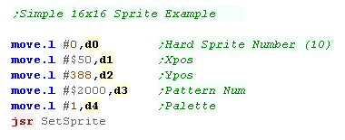
Drawing a simple 16x16 sprite
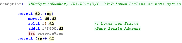
| We're going to learn how to draw a simple sprite - we'll create a
function called "SetSprite" to handle this for us - We'll pass 'Sprite number' (the hardware sprite num we want to configure) in DO... a screen location X,Y in D1,D2.... the Tile pattern number (in rom) in D3 |
 |
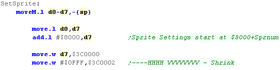
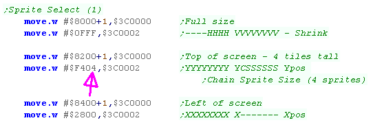
| Ok, lets set up the sprite... First we're going to set up the 'Shrink' scale... this is at address $8000 + the sprite number We select the address in VRAM using memory mapped port $3C0000 we set all the scale bits to 1 ($0FFF)... this is 'Normal size' - anything else would be smaller... We set the new value using memory mapped port $3C0002 |
 |
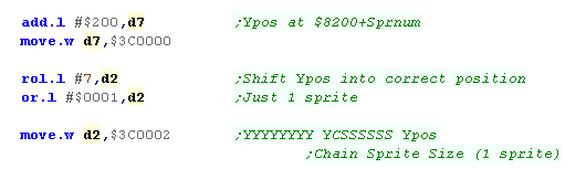
| Next we want to set the Y position... the address in VRAM we need
to write to is $8200+ the sprite number - so we add $200 to our
write position... We need to shift our Y position to bit 7 of the word, as the low bits handle the height (and horizontal chaining) of the sprite we need to add 1 to the low byte - so our sprite has a height of 1 |
 |
| Next is the turn of the X position.... this has it's VRAM address at &8400+ the sprite number, so again we add $200 our write position | 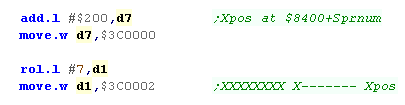 |
| The rest of the attributes are at VRAM address $0000 + sprnum*64 We multiply the sprite number in D0 by 64 by bitshifting to the left 6 times |
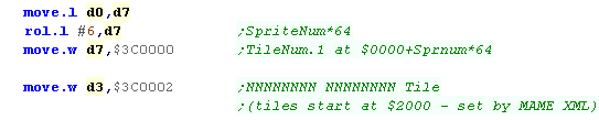 |
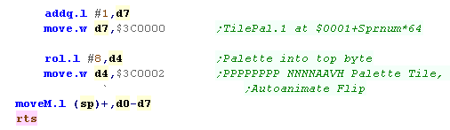
| Next we need to set the palette at $0001+sprnum*64... so we add
one to the last address We need to set the top byte to our palette number. In this simple example, we don't use the low byte... the low byte handles V/H flipping, Automatic sprite animation, and the top 4 bits of the Tile Number (it's 20 bit in total) |
 |
 |
Chaining sprites for big sprites (32x64), and scaling!
| We're going to do something a little more complex this time... We're going to define our first sprite with 4 tiles - making it 16x64.... we're also going to 'chain' it to a second sprite... the result is an 'sprite' 32x64 in size! To define the sprite as 4 tiles tall we need to set the low byte of &8200+sprnum to 04 |
 |
| We need to define the 4 tiles for this sprite... Each has a Tile number , Palette and other options... Of course, each has to have a consecutive tile ($2001-$2004)... matching the sprite ROM export from AkuSprite Editor |
 |
| Ok, that's the left side of our sprite done... now we need to do
the second 16 pixel wide strip... We need to use the immediately consecutive sprite to the last one for the chain to work... we need to set bit 6 of the attribute at $8200+SprNum We do this by writing $0040 to $8200+2... because we do this, the X,Y position,Tile count and Vertical Shrink are ignored... The Horizontal Shrink, however can still be used. |
 |
| We need to set all the tiles for the 2nd sprite. |
 |
| The combined sprite will be show onscreen at fullsize | 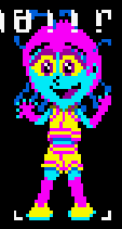 |
| If we want, we can scale the sprite by altering the 'Shrink' In this case we've used a shrink of 50%, by changing the scaling option from $0FFF to $0880 |
 |
| The scaled sprite will be shown to screen... easy! |  |
|
We
can scale sprites DOWN, but not up... If you want to make a sprite bigger... scale it up in the rom... and then show it scaled down to begin with! |
| You'll probably
notice that the sprites appear beneath the text, and are wondering
how to make them in front? Well You can't! the text is in the FIX layer, and that's always at the top... if you need text behind, you'll have to create a font as sprites, and use those sprites to print letters. Not fun... but that's how the NeoGeo works! |
|
Using Sprites as a Tilemap
| We're going to define as set of sprite tiles - and use these as tiles for an example - because NeoGeo Sprite patterns are 16x16 - we need our tiles to be the same - we can set the 'shrink' to 50% if we really want 8x8 tiles. | 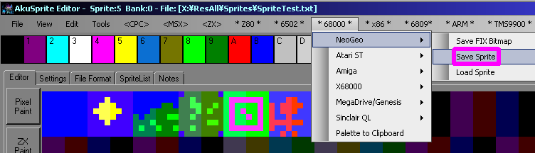 |
| Our 'Tilemap' is built up of a set of sprites... one for each
column... the first will be the Anchor sprite... the other columns will be Chained to that sprite... the Rows of the tilemap are made up of the tiles of those sprites... (Remember: each sprite can be up to 32 tiles tall!) |
 |
| We need to do a
bit of work to set up the tilemap sprites, but once they are set
up and on screen, we just need to change the tile numbers in
memory just like a 'real' tilemap! Thanks the 'Chaining' option of the NeoGeo, it's pretty easy, and the NeoGeo's scaling option allows for flexibility in tilesize, and allows for zooming. |
|
Defining a Tilemap
| Ok, first we need to set the tilemap sprites up... First we need some registers with the default scale, and width and height of the map... the required Width/Height will depend on the shrink... A shrink of around $077F makes a tilemap where each tile is about 8x8... $0FFF is 'fullsize' 16x16 |
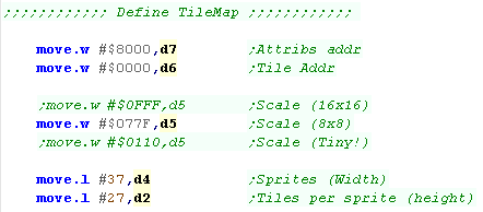 |
| The Tilemap has a single 'anchor sprite'... the other sprites will
chain to this, so we can make the map scroll by changing this
sprites position... all other sprites will also share it's Y-height
and Y-Shrink (but not the Xshrink) We use D7 to point to each of the attributes, resetting it once we're done... we'll need it again for the Chained sprites. We set the Height in tiles to 33 - this is a special setting which sets the height to the full height of the screen. |
 |
| Ok, we need to set up the Tiles in this sprite... for now we set them all to tile $2010, Palette 1 (we'll set a proper Tile Number later)... Note: this routine handles both the first Anchor sprite, and the later Chained sprites. |
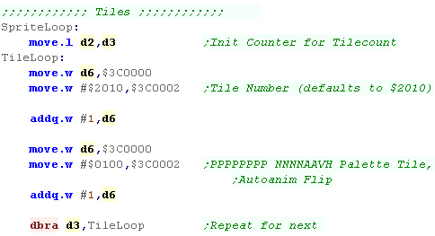 |
| Ok, we've done one of our sprites... now we need to start the
Chained sprite, This is similar to the first Anchor sprite, but we set the Chain bit, so it attaches to the first sprite. We then repeat the Tile routine until the tilemap is drawn |
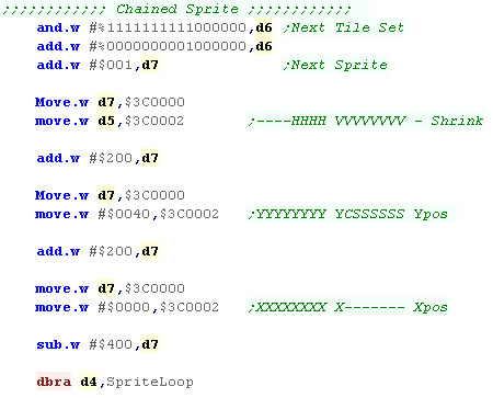 |
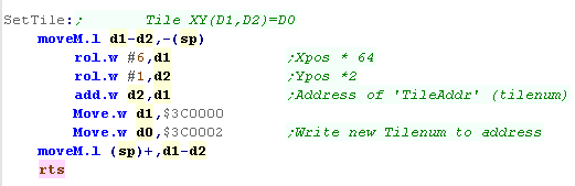
Setting tiles in our tilemap
| The Sprites we need to hold our tilemap are set up, but we need a
way to set a tile to the pattern we want... We're going to define a function called 'SetTile'... it will set X,Y Tile (D1,D2) to tilenumber D0... We need to calculate the Sprite and Tilenumber... D1 is the sprite - we multiply this by 64... D2 is the Tile - each tile is 2 bytes, so we double it. We then set the sprite tile number to D0 |
 |
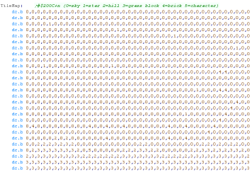
| We're defining a grid of bytes for the first values of the tile
numbers... Each is defined by a single byte, though the sprites we'll actually use for tiles start at $200C |
 |
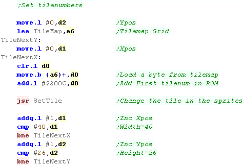
| Ok, lets read in bytes from our Tilemap definition, and use the
SetTile function to set the tiles. We just read in bytes from the tilemap (in A6) Add the Sprite number of the first tile $200C |
 |
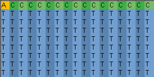
| The Result can be seen here | 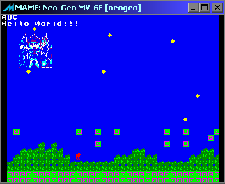 |
|
If
the tiles are 16x16, then we need 20 tiles to fill the width of
the screen... as the neogeo can only draw 96 sprites on the same
scanline, we could manage up to 4 layers of tilemaps... but then
we'd only have 16 tiles left for our game! We'll have to decide how we want our game to play, and design things accordingly! |
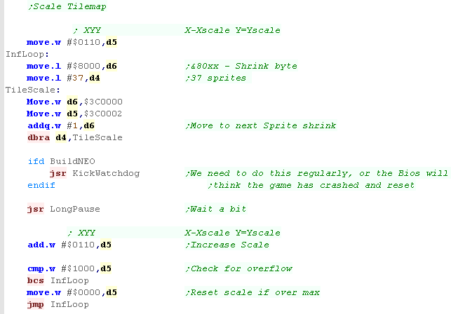
Scaling the tilemap
| Because of the advanced capabilities of the Neogeo Sprites, we can
effect scaling of the tilemap as required... If we scale X and Y together, and all chained sprites at the same rate, In this example there will be a total of 16 steps from min-scale ($0110) to max ($0FF0) |
 |
| the tilemap will be scaled accordingly | 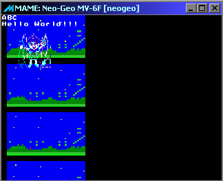 |
|
If we scale up
the tilemap too large, then it may wrap around the screen... which
will make a mess! Also we only have 16 scale options for the width... which may not give smooth enough scaling for a 'zoom', we'd probably want to do some kind of 'betweening' to fix this... for example: to effect a scale of 14.5, we could scale the tiles alternately, eg: 14,15,14,15,14,15 |
Hardware Sprites on the Genesis
In H40 mode (the mode used in these tutorials), we can have
up to 80 sprites onscreen... (H32 mode can do only 64)
Each sprite can be 8x8 to 32x32
The position (and other settings) are defined by 8 bytes (4 Words) per
sprite.
| Address | Sprite Num | Details |
| $D800 | 1 | Ypos |
| $D802 | 1 | Size,Link |
| $D804 | 1 | Palette,Flip,Pattern |
| $D806 | 1 | Xpos |
| $D808 | 2 | Ypos |
| $D80A | 2 | Size,Link |
| $D80C | 2 | Palette,Flip,Pattern |
| $D80E | 2 | Xpos |
| $D810 | 3 | Ypos |
| � | ||
| $D9FF | 64 | Xpos � Last Sprite of H32 |
| � | ||
| $DA7F | 80 | Xpos � Last Sprite of H80 |
As we can see, Each sprite has 4 words, they use the same pattern data as the background...
| Address | F | E | D | C | B | A | 9 | 8 | |
7 | 6 | 5 | 4 | 3 | 2 | 1 | 0 | Details |
| $D800 | - | - | - | - | - | - | Y | Y | Y | Y | Y | Y | Y | Y | Y | Y | Y-Pos | |
| $D802 | - | - | - | - | W | W | H | H | - | L | L | L | L | L | L | L | Width (8,16,24,32), Height (8,16,24,32), Link (to next sprite - draw order, NOT related to large sprites) | |
| $D804 | P | C | C | V | H | N | N | N | N | N | N | N | N | N | N | N | Priority (0=front), Color palette , Vflip, Hflip, tile Number | |
| $D806 | - | - | - | - | - | - | - | X | X | X | X | X | X | X | X | X | X-pos |
You MUST link your sprites!!! The 'Link' Connects the sprites together, each sprite should point to the next (starting from Sprite 0) and the last sprite should point back to sprite 0, this is not like neogeo chaining, it doesn't make the sprites move together - it defines the 'draw order' of the active sprites.
Multi pattern Sprites
| A basic sprite is 8x8, but sprites can be enlarged up to 32x32...
however this sprite will still be made up of 8x8 pattern data...
If we want a larger sprite, we need to break up the sprite into 8x8 blocks, and save those in VRAM in the correct order - the tiles go down first, and across second, as shown below:
Sprites can be exported in the correct format with my AkuSprite Editor |
 |
Using Sprites in our code
| Using the hardware sprites is easy! We're going to create a function to set the sprite for us... We'll specify the 'hardware sprite number' in D0... Because each hardware sprite has settings in 8 addresses, we multiply by 8 with a ROL #3 to calculate the correct offset for the sprite... We then add #D800, as this is the base of the sprite data in VRAM... we then use our 'PrepareVRAM' function to select that ram address for writing |
 |
| Once we've selected our memory address, we just need to transfer our 4 data values into the VRAM, and we're done! | 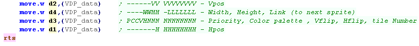 |
| First we need to transfer the pattern data for our sprite into VRAM... we use the same DefineTiles Function we used for the Tilemap | 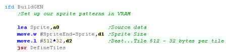 |
| We're going to use this function to draw 2 sprites to the
screen... each 32x32 (Size &F) The first is sprite 0 - Note the Link byte points to sprite 1 The second is sprite 1 - Note the Link byte points back to the start (to sprite 0) |
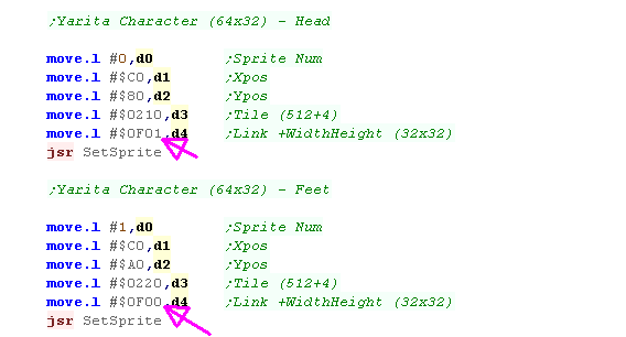 |
| Due to the XY Position The two sprites are drawn together to make one 32x64 character | 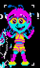 |
|
Each
sprite is made up of 32x32 tiles... and the two tiles have been
combined to make a 32x64 image! We'll have to make sure our byte data for the sprite is the correct format to match this! |
Hardware Sprites
| There are 8 hardware sprites on the Amiga, Hardware Sprites are 16
pixels wide, and can be any height... each sprite is 4 colors
(2bpp), but Sprites 0&1, 2&3 etc Hardware sprites use a set of pointers, pointing to a sprite table in 'Chip Ram'... this table defines a series of XY positions and bitmap data, that are used by the sprite DMA to define the image... The format of the header is as follows:
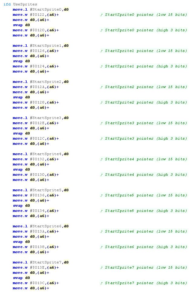
The end of each Sprite list ends 0,0 We need to define the pointers to the sprite data, we do this in the Copperlist in the following way: move.l #StartSprite0,d0 move.w #$0122,(a6)+ ; StartSprite0 pointer (low 15 bits) move.w d0,(a6)+ swap d0 move.w #$0120,(a6)+ ; StartSprite0 pointer (high 3 bits) move.w d0,(a6)+ The pointer addresses for other sprites are shown in the table below, you should define all the sprites, even if they point to an empty list... Once we've defined our sprites, we need to turn the sprite DMA on: move.w #%1000001000100000,DMACON ; DMA set ON - DMA control (and blitter status) read |
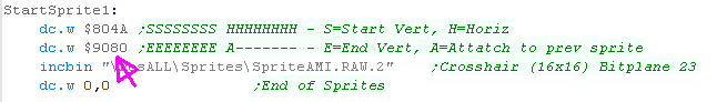
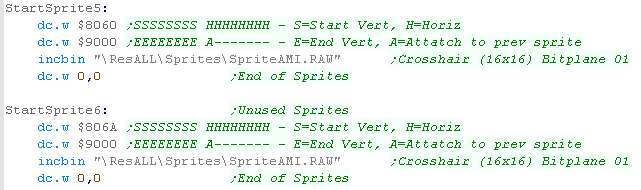
Sample Sprite Data: StartSprite0: dc.w $804A,$8800 ;Header dc.w $0001,$0304 ;Bitmap Data dc.w $0001,$0304 dc.w $0001,$0304 dc.w $0001,$0304 dc.w $0001,$0304 dc.w $0001,$0304 dc.w $0001,$0304 dc.w $0001,$0304 dc.w $A070,$A800 ;Header dc.w $0304,$0001,$0304 ;Bitmap Data dc.w $0001,$0304 dc.w $0001,$0304 dc.w $0001,$0304 dc.w $0001,$0304 dc.w $0001,$0304 dc.w $0001,$0304 dc.w $0001 dc.w 0,0 ;End of Sprites StartSprite1: dc.w $804A,$8880 ;header dc.w $0001,$0304 ;Bitmap Data dc.w $0001,$0304 dc.w $0010,$0403 dc.w $0010,$0403 dc.w $0304,$0001,$0304 dc.w $0010,$0403 dc.w $0010,$0403 dc.w $0001 dc.w 0,0 ;End of Sprites StartSprite2: ;Unused Sprites StartSprite3: StartSprite4: StartSprite5: StartSprite6: StartSprite7: dc.w 0,0 ;End of Sprites |
Sprite Pointers
The hardware sprites are defined by the following Chip Registers
| NAME |
|
ADD | R/WD | Chip | Function |
| DMACON | 96 | W | ADP | DMA control write (clear or set) | |
| SPR0PTH | + | 120 | W | A | Sprite 0 pointer (high 3 bits) |
| SPR0PTL | + | 122 | W | A | Sprite 0 pointer (low 15 bits) |
| SPR1PTH | + | 124 | W | A | Sprite 1 pointer (high 3 bits) |
| SPR1PTL | + | 126 | W | A | Sprite 1 pointer (low 15 bits) |
| SPR2PTH | + | 128 | W | A | Sprite 2 pointer (high 3 bits) |
| SPR2PTL | + | 12A | W | A | Sprite 2 pointer (low 15 bits) |
| SPR3PTH | + | 12C | W | A | Sprite 3 pointer (high 3 bits) |
| SPR3PTL | + | 12E | W | A | Sprite 3 pointer (low 15 bits) |
| SPR4PTH | + | 130 | W | A | Sprite 4 pointer (high 3 bits) |
| SPR4PTL | + | 132 | W | A | Sprite 4 pointer (low 15 bits) |
| SPR5PTH | + | 134 | W | A | Sprite 5 pointer (high 3 bits) |
| SPR5PTL | + | 136 | W | A | Sprite 5 pointer (low 15 bits) |
| SPR6PTH | + | 138 | W | A | Sprite 6 pointer (high 3 bits) |
| SPR6PTL | + | 13A | W | A | Sprite 6 pointer (low 15 bits) |
| SPR7PTH | + | 13C | W | A | Sprite 7 pointer (high 3 bits) |
| SPR7PTL | + | 13E | W | A | Sprite 7 pointer (low 15 bits) |
Hardware Sprites Pixel data
| The Sprites are always 16 pixels
wide, and by default 2bpp (4 colors)... each line of the sprite is
made up of 2 words of data... The first Word is effectively the 1st bitplane of the sprite. The second Word is effectively the 2st bitplane of the sprite. The third word will be the 1st bitplane of the 2nd line - and so on! If we attach Sprite 1 to Sprite 0 - we effectively increase it to 16 colors (4bpp) - adding an extra 2 bit-planes to the sprite! Note: We can only attach pairs of sprites, 0+1, 2+3, 4+5 or 6+7... we cannot attach sprite 0 to sprite 2! |
|
|||||||||||||||||||||||||||||||||||||||||||||||||||||||
| You can save sprites in the correct format for the Amiga using my
AkuSprite editor! It will save a pair of files for each sprite, allowing for 2bpp (4 color) or combined for 4bpp (16 color) |
 |
|||||||||||||||||||||||||||||||||||||||||||||||||||||||
Turning on Hardware Sprites
| To start using the hardware sprites, we need to set pointers in
the Chip Registers, pointing the 8 pointers to areas of Chip Ram
which will define the sprites... Even if we're not going to use all the sprites, we need to point the unused ones to empty sprites |
 |
| Once we've set up the pointers, we need to turn on the DMA - this will start sprites drawing! | 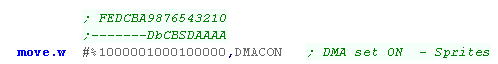 |
Defining a single hardware sprite
| We're going to define a 16 pixel tall sprite ($10)... it's going to start at Ypos $80 - so it'll end at $90 | 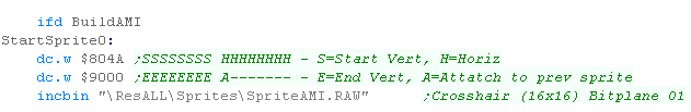 |
| We need to blank out any unused sprites | 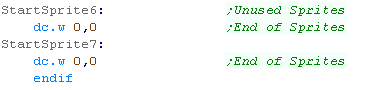 |
| The 4 color sprite will be shown. |  |
| We can 'Attach' a second sprite to the first - the extra 2bpp will
be added, making the sprite 4bpp... we need the second sprite to
attach to the first.. We set the attach bit (byte $80) to do this |
 |
| The sprite will now be a 16 color sprite |  |
| If the second layer doesn't line up properly, our sprite will look weird. |  |
| We can use one hardware sprite to draw two sprites onscreen, povided they do not overlap on the X axix... the second sprites Y position are beneath the first sprite | 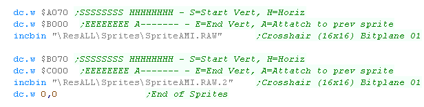 |
| The one hardware sprite has been used to draw two vertical sprites onscreen! |  |
| Because of the
way the Amiga sprites work, we can get a lot of sprites on the
screen, provided they don't all appear on the same X-line! We'll have to design our game in a way the sprites work well for us, but don't cause problems with the limitations, for example, using hardware sprites for the main character (and software for enemies) could work, or using them for foreground paralax could work well. |
|
4 color 2bpp Hardware Sprites Colors
The colors our sprite appears may depend on the sprite number!
4 color Hardware sprites use 3 colors from palette 17-31... color 0 is
always transparent... the colors vary depending on the sprite number
16 color sprites use colors 17-31
| Sprite number |
Palette numbers |
| 0, 1 |
17, 18, 19 |
| 2, 3 |
21, 22, 23 |
| 4, 5 |
25, 26, 27 |
| 6, 7 |
29, 30, 31 |
| Lets see the effect of the colors on 4bpp sprites, If we show the same sprite with sprite 5 and 6... they will use different palettes, As stated above, 4,5 share a palette , and 6,7 do... but 5 and 6 will be different colors! |
 |
| We can see the result here: |  |
| Equally, we cannot combine sprites that are not matching pairs...
if we try to Attach sprite 4 to sprite 6, or even sprite 5 to sprite
6... the pair will not work and our colors will be wrong You can see the result here. |
 |
Tilemaps!
There are 3 Tilemaps on the Genesis... Scroll-A and Scroll-B are 2 scrolling layers of tilemap... There is a 3rd known as the 'Window' which cannot scroll - it's intended as a HUD and replaces Scroll-A. a 'Fixed point' is defined on the screen, and everything above or below, and to the Left or Right of that point is the window (meaning it cannot be in the centre). Depending on the tile priority Window can be in front of, or behind Scroll-B The VRAM address of these is defined by various registers, here are the suggested defaults.
|
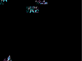
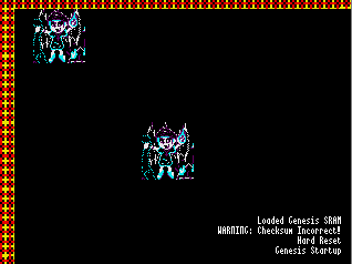 Two Chibikos on tilemaps A and B... the 'Window' is filled with plus tiles. |
||||||||||||
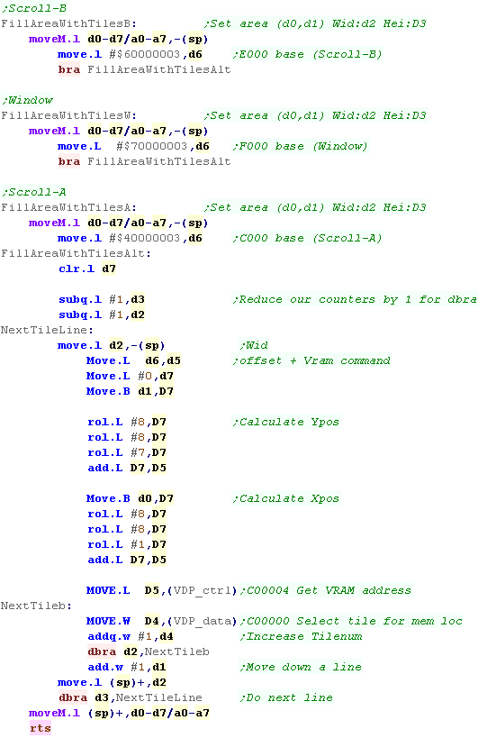
| Here we've written two new versions of 'Fill Area with tiles'...
they are exactly the same as the old one, they just write to
different tilemap bases. We're using Tile 257 onwards... we can set bit 15 to 1 to set a tile to the 'foreground' (priority bit) |
 |
||||||||||||
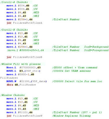
| We're using these functions to draw '3 chibikos'... these use tile
257+ We also fill the Window manually with tile 256 (in palette 2 = $2100) - this is the plus pattern filling the window. |
|
||||||||||||
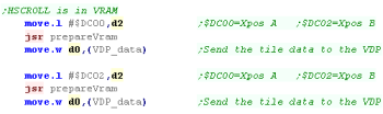
| Here we're scrolling the tilemaps as a single unit. The horizontal scroll is in VRAM at addresses $DC00 for Scroll-A and $DC02 for Scroll-B The window cannot scroll! |
|
||||||||||||
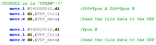
| The vertical scroll is in 'VSRAM' - this is special scroll memory,
accessed with a command like color ram. #$40000010 selects address VSRAM address $000 for Scroll-A #$40020010 selects address VSRAM address $002 for Scroll-B The window cannot scroll! |
 |
||||||||||||
| We cannot scroll the window, but we can alter the area of the
screen it covers. We do this with registers 17 and 18... The bottom 5 bits define the window base, Reg 17 defines the Xpos, Reg 18 defines the Ypos The top bit of these (bit 7) define if the window goes Up/Down or Left/Right from this basepoint. |
 |
Scrolling
| Scrolling on the Genesis is odd!
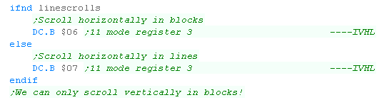
Normally we would scroll the whole tilemap horizontally and vertically by a number of pixels... but we can actually do more! If we wish,We can scroll individual 'Strips' of the tilemap by different amounts!... We can scroll the Vertical strips in 'chunks' of 16 pixels (Two tiles) We can scroll the horizontal strips in 'chunks' of 8 pixels (one tile) OR even one line! These are defined by reg R11... a setting of $00 scrolls the
whole tilemap in one unit. $06 scrolls in blocks, $07 scrolls
horizontally in lines (vertically always scrolls in 'Chunks' Vertical scrolling is defined by something called 'VSRAM' it's defined like the palette with special addresses. where as colors use the $C000 range, VSRAM use the $A000 range
|
 Block Scrolling 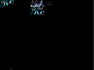 Line Scrolling |
|||||||||||||||
| Register 11 defines how the scroll works. $00 will scroll the whole tilemap as one object $06 Scrolls the screen horizontally and vertically in blocks $07 Scrolls the screen horizontally in lines and vertically in blocks We cannot scroll vertically in lines! |
 |
|||||||||||||||
| We now have more VRAM and VSRAM addresses we can use to scroll parts of the tilemaps. | 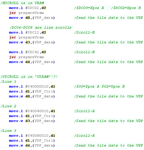 |
|
We
can scroll all the lines of the screen separately if we want, this
can be used to create a parallax effect, and unlike other systems,
we don't have to use line interrupts to do it! |
 |
Lesson
P30 - The X68000 Mouse The X68000 is a powerful PC, so it's no surprise that is has a mouse. Lets learn how to put that mouse to work! |
 |
 x68_Mouse.asm |
 |
Taming the mouse!
The X68000 Mouse can be controlled via Trap #15 - the option is selected with the value in D0.
The operating system can show a cursor and even create a limited range (handy for games like DUNE 2), but the mouse cursor can be read with no cursor visible, and 'movement amounts' can be measured with $74 (handy for games like DOOM)
|
Trap #15
D0 |
Name | Function | Params | Returns | Notes |
| $70 | _MS_INIT | Mouse Init | |||
| $71 | _MS_CURON | Cursor On | |||
| $72 | _MS_CUROF | Cursor Off | |||
| $73 | _MS_STAT | Get Cursor Status | D0=status | ||
| $74 | _MS_GETDT | Get Buttons + Move amount | D0=$XXYYLLRR | ||
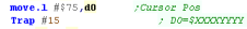
| $75 | _MS_CURGT |
Get Cursor Pos | D0=$XXXXYYYY | ||
| $76 | _MS_CURST | Set Cursor Pos | D1=$XXXXYYYY | D0=Success? | |
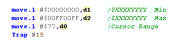
| $77 | _MS_LIMIT | Set Range Limits (X,Y)-(x,y) | D1=$XXXXYYYY D2=$xxxxyyyy | ||
| $78 | _MS_OFFTM | Check time until mouse button was released | D1=Button (0/1=L/R) D2=Wait Time | D0=Drag/Wait | |
| $79 | _MS_ONTM | Time until mouse button pressed | D1=Button (0/1=L/R) D2=Wait Time | D0=Drag/Wait | |
| $7A | _MS_PATST | Set Cursor Graphic | D1=PatternNum A1=Graphic Address | 18 words� 1W: center pos X 1W: centercPos Y 16W: Shadow graphic 16W: Cusor Graphic |
|
| $7B | _MS_SEL | Select Cursor Graphic | D1=PatternNum | ||
| $7C | _MS_SEL2 | Select Animated Cursor | A1=Graphic Address | Up to 6 words� Each is a cursor number -1=End |
|
| $7D | _SKEY_MOD | Show/Hide Soft Keyboard |
D1=0/1/2/-1 (Off/On/Check/Auto) D2=$XXXXYYYY |
D0=State |
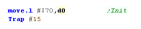
Setting up the mouse
| We can initialize the mouse with Trap #15
function $70 We don't need to do this, but it's probably best to. |
 |
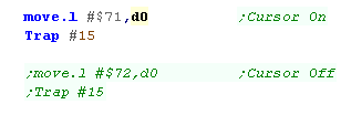
| If we want to show the cursor, we
can use function $71 If we want to hide the cursor we can use function $72 |
 |
| Here's our lovely cursor! |  |
| We can limit the area of the
screen that our mouse can cover using function $77 D1 specifies the Top left of the area... D2 specifies the bottom right. In the passed Long. The top word is the X co-ordinate, the bottom word is the Y co-ordinate |
 |
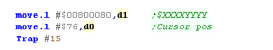
| We can move the cursor to a
specified location with function $76 D1 specifies the new location.The top word is the X co-ordinate, the bottom word is the Y co-ordinate |
 |
The soft keyboard
| The X68000 has this snazzy soft keyboard which will appear when we right click... great for operating the machine with just a mouse... but it'll probably get in the way of our amazing game! | 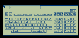 |
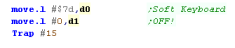
| Fortunately, we can turn off the soft
keyboard with function $7D. Setting D0 to 1 turns off the keyboard |
 |
Reading the mouse
| We can get the status of the buttons, and the movement amount with function $74... | 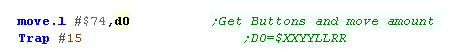 |
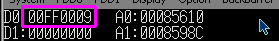
| The top byte of the returned D0 will be the X-move, the next byte
will be the Y-Move, the third byte will be the Left button state,
the final byte will be the right button Here we were moving right ($01) and pressing Left mouse ($FF) |
 |
| We can get the current screen position
with function $75 This returns the X,Y position in D0.The top word is the X co-ordinate, the bottom word is the Y co-ordinate |
 |
| Here the mouse cursor was at (X,Y) position (255,9) However, We still need function $74 to read the mouse buttons! |
 |
| View Options |
| Default Dark |
| Simple (Hide this menu) |
| Print Mode (white background) |
| Top Menu |
| ***Main Menu*** |
| Youtube channel |
| Patreon |
| Introduction to Assembly (Basics for absolute beginners) |
| Amazon Affiliate Link |
| AkuSprite Editor |
| ChibiTracker |
| Dec/Bin/Hex/Oct/Ascii Table |
| Alt Tech |
| Archive.org |
| Bitchute |
| Odysee |
| Rumble |
| DailyMotion |
| Please note: I wlll upload more content to these alt platforms based on the views they bring in |
| 68000 Content |
| ***68000 Tutorial List*** |
Learn 68000 Assembly  |
| Hello World Series |
| Platform Specific Series |
| Simple Samples |
| Grime 68000 |
| 68000 Downloads |
| 68000 Cheatsheet |
| Sources.7z |
| DevTools kit |
| 68000 Platforms |
| Amiga 500 |
| Atari ST |
| Neo Geo |
| Sega Genesis / Mega Drive |
| Sinclair QL |
| X68000 (Sharp x68k) |
| 8086 Content |
| Learn 8086 Assembly |
| Platform Specific Series |
| Hello World Series |
| Simple Samples |
| 8086 Downloads |
| 8086 Cheatsheet |
| Sources.7z |
| DevTools kit |
| 8086 Platforms |
| Wonderswan |
| MsDos |
| ARM Content |
| Learn ARM Assembly |
| Learn ARM Thumb Assembly |
| Platform Specific Series |
| Hello World |
| Simple Samples |
| ARM Downloads |
| ARM Cheatsheet |
| Sources.7z |
| DevTools kit |
| ARM Platforms |
| Gameboy Advance |
| Nintendo DS |
| Risc Os |
| Risc-V Content |
| Learn Risc-V Assembly |
| Risc-V Downloads |
| Risc-V Cheatsheet |
| Sources.7z |
| DevTools kit |
| MIPS Content |
| Learn Risc-V Assembly |
| Platform Specific Series |
| Hello World |
| Simple Samples |
| MIPS Downloads |
| MIPS Cheatsheet |
| Sources.7z |
| DevTools kit |
| MIPS Platforms |
| Playstation |
| N64 |
| PDP-11 Content |
| Learn PDP-11 Assembly |
| Platform Specific Series |
| Simple Samples |
| PDP-11 Downloads |
| PDP-11 Cheatsheet |
| Sources.7z |
| DevTools kit |
| PDP-11 Platforms |
| PDP-11 |
| UKNC |
| TMS9900 Content |
| Learn TMS9900 Assembly |
| Platform Specific Series |
| Hello World |
| TMS9900 Downloads |
| TMS9900 Cheatsheet |
| Sources.7z |
| DevTools kit |
| TMS9900 Platforms |
| Ti 99 |
| 6809 Content |
| Learn 6809 Assembly |
| Learn 6309 Assembly |
| Platform Specific Series |
| Hello World Series |
| Simple Samples |
| 6809 Downloads |
| 6809/6309 Cheatsheet |
| Sources.7z |
| DevTools kit |
| 6809 Platforms |
| Dragon 32/Tandy Coco |
| Fujitsu FM7 |
| TRS-80 Coco 3 |
| Vectrex |
| 65816 Content |
| Learn 65816 Assembly |
| Hello World |
| Simple Samples |
| 65816 Downloads |
| 65816 Cheatsheet |
| Sources.7z |
| DevTools kit |
| 65816 Platforms |
| SNES |
| eZ80 Content |
| Learn eZ80 Assembly |
| Platform Specific Series |
| eZ80 Downloads |
| eZ80 Cheatsheet |
| Sources.7z |
| DevTools kit |
| eZ80 Platforms |
| Ti84 PCE |
| IBM370 Content |
| Learn IBM370 Assembly |
| Simple Samples |
| IBM370 Downloads |
| IBM370 Cheatsheet |
| Sources.7z |
| DevTools kit |
| Super-H Content |
| Learn SH2 Assembly |
| Hello World Series |
| Simple Samples |
| SH2 Downloads |
| SH2 Cheatsheet |
| Sources.7z |
| DevTools kit |
| SH2 Platforms |
| 32x |
| Saturn |
| PowerPC Content |
| Learn PowerPC Assembly |
| Hello World Series |
| Simple Samples |
| PowerPC Downloads |
| PowerPC Cheatsheet |
| Sources.7z |
| DevTools kit |
| PowerPC Platforms |
| Gamecube |
| Work in Progress |
| ChibiAndroids |
| Misc bits |
| Ruby programming |
Buy my Assembly programming book
on Amazon in Print or Kindle!


Available worldwide!
Search 'ChibiAkumas' on
your local Amazon website!
Click here for more info!


Buy my Assembly programming book
on Amazon in Print or Kindle!
Available worldwide!
Search 'ChibiAkumas' on
your local Amazon website!
Click here for more info!
Buy my Assembly programming book
on Amazon in Print or Kindle!
Available worldwide!
Search 'ChibiAkumas' on
your local Amazon website!
Click here for more info!