

6510 Assembly programming for the Commodore 64
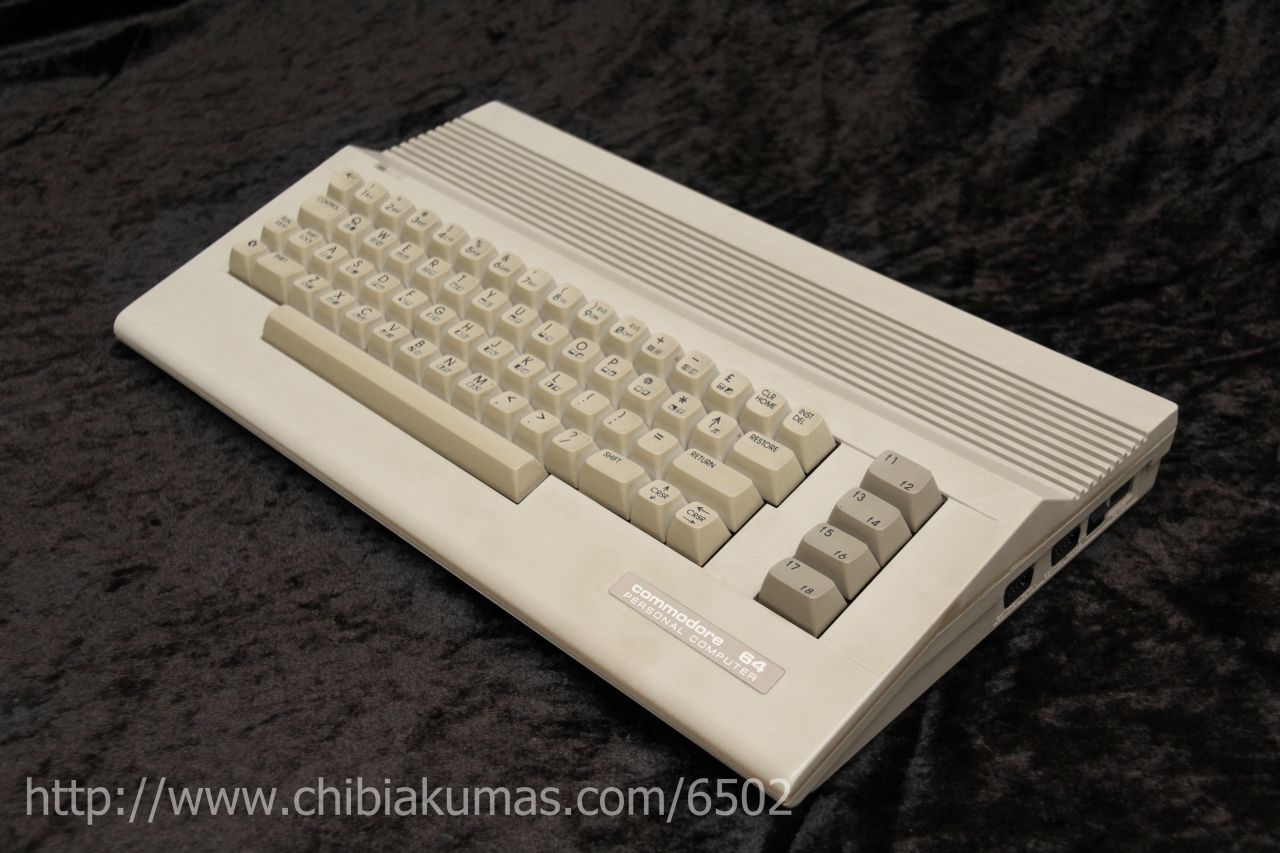
| The C64 is one of the most popular
computers of all time, although limited to just 64k, it rivalled its
competitors with hardware sprites and scrolling, its 6510 CPU is a 6502 with built in IO ports... the is no programming difference |
 |
 |
 |
|
 |
ChibiAkumas Tutorials
| Lesson H2 - Hello World on the C64 | |
| Lesson S2 - Bitmap Drawing on the C64 | |
| Lesson P9 - Bitmap Functions on the C64 | |
| Lesson P30 - Sound on the C64 | |
| Lesson P36 - Hardware Sprites on the C64 |
 |
*** Linux and Mac users! *** Viewer "Kevin Thomas" has done a lot of work porting the C64 Chibiakumas tutorials to Linux and Unix - so if you're using those systems, you should probably check out his work over Here! |
Text Graphics
The characters shown onscreen are selected by the bytes in the memory range $0400-$07FF (These addresses change as the screenbase moves), the colors of the tiles are selected per 8x8 square, from the registers at $D800-$DBE7... only the Low nibble of this area is used.Bitmap Graphics
There are two modes for Bitmap graphics on the C64
Normal mode is 320x200... it has 2 colors per 8x8 tile, the "Bitmap data" is typically located between $2000-$3FFF, this is a 1 bpp bitmap, each tile will get its background color from the low nibble of $D020, and it:s foreground color from the low nibble of $D800-$DBE7
| Bits | Detail | Address | Bits |
| 0 | Text Screen Mem - Low nibble | ScreenBase+$0400-$07FF | ----CCCC |
| 1 | Text Screen Mem - High nibble | ScreenBase+$0400-$07FF | CCCC---- |
Multicolor Mode is 160x200 , it has 4 colors per 4x8 tile, but setting those colors is more tricky... again it uses a bitmap screen at $2000-$3FFF, but is 2bpp... it uses a 160x200, 2 bits for each pixel choose a color from 1 of 4 locations
| Bits | Detail | Address | Bits |
| 00 | Background Color | $D021 | ----CCCC |
| 01 | Text Screen Mem - Low nibble | ScreenBase+$0400-$07FF | ----CCCC |
| 10 | Text Screen Mem - High nibble | ScreenBase+$0400-$07FF | CCCC---- |
| 11 | Color Memory - Low Nibble | $D800-$DBFF | ----CCCC |
The Border Color is defined by $D020
Graphics Memory and ports
| Address | Description | Bits | Meaning |
| $0400-$07E7 | Default area of screen memory | (1000 bytes). | |
| $2000-$3FFF | BMP Screen Ram | ||
| $D000-$D7FF | Char ROM in uppercase/graphics character set | (2048 bytes, 256 entries) | |
| $D800-$DFFF | Char ROM in lowercase/uppercase character set | (2048 bytes, 256 entries) | |
| $D011 | Screen control register #1. | LXMSHVVV | L=Cur Line X=extended BG M=mode (Txt/Bmp)S=screen on H=height V=Vert scroll |
| $D012 | Raster line of IRQ (RW) | LLLLLLLL | L=Raster Line
of IRQ |
| $D016 | Screen control register #2 | ---MWHHH | M=Multicolor W=scr width H=horiz scroll |
| $D018 | Memory setup register. | SSSSTtt- | Ttt=Text
screen addr offset (multiples of $800) T=Bmp screen addr offet ($0000/$2000) S=Screen (color) addr offset (multiples of $400) |
| $D020 | Border color | ----CCCC | C=color |
| $D021 | Background color | ----CCCC | C=color |
| $D022 | Extra background color #1 | ----CCCC | C=color |
| $D023 | Extra background color #2 | ----CCCC | C=color |
| $D024 | Extra background color #3 | ----CCCC | C=color |
| $D800-$DBE7 | Color RAM | ----CCCC | C=color (1000 bytes). |
Palette
| 0 | 1 | 2 | 3 | 4 | 5 | 6 | 7 |
| 8 | 9 | A | B | C | D | E | F |
C64 Sprites
The Sprite pointers for the bitmap data are a single byte... multiplying
the sprite pointer by 64 will give the address of the sprite *within the
16k bank of Vram* (so must be in the range $0000-$3FFF)...
$1000-$2000 and $9000-$A000 are seen by the VIC as character ROM, so
sprites cannot be in this area!
We can move our screen base to something more convenient... so for example
with a screen base of $4000 (Screen ram at $6000)- our sprites can be at
$5000
| $D018 Memory setup register. |
$DD00 Vic 2 bank (Bottom 2 bits) |
Screen Base |
Sprite Patterns |
Sprite Pointers |
| %00011000
(Screen base $2000 / Colors at $400) |
%------10 (Bank $4000-7FFF) |
$6000 ($4000+$2000) |
$5000 (one option) $4000+? |
$47F8 ($4000+$7F8) |
Sprites are 21 vertical lines and 63 bytes each. With one unused byte
this makes a 64 byte pattern size.
In 1bpp (2 color) mode this makes sprites 24x21.
In 2bpp (4 color) mode they are 12x21.
In both modes, Color 0 is Transparent
In 2bpp mode color 1,2 are read from $D025/6 and color 3 is the sprite
color.
The Top Left first visible co-ordinate is (24,50)
| Address | Purpose | Bits | Meaning |
| ScreenBase+ $07F8-$07FF |
Sprite
pointers (default - will change if screen moved) |
SSSSSSSS | s*64=memory address |
| $D000 | Sprite #0 X-coordinate | XXXXXXXX | (only bits #0-#7). |
| $D001 | Sprite #0 Y-coordinate | YYYYYYYY | |
| $D002 | Sprite #1 X-coordinate | XXXXXXXX | (only bits #0-#7). |
| $D003 | Sprite #1 Y-coordinate | YYYYYYYY | |
| $D004 | Sprite #2 X-coordinate | XXXXXXXX | (only bits #0-#7). |
| $D005 | Sprite #2 Y-coordinate | YYYYYYYY | |
| $D006 | Sprite #3 X-coordinate | XXXXXXXX | (only bits #0-#7). |
| $D007 | Sprite #3 Y-coordinate | YYYYYYYY | |
| $D008 | Sprite #4 X-coordinate | XXXXXXXX | (only bits #0-#7). |
| $D009 | Sprite #4 Y-coordinate | YYYYYYYY | |
| $D00A | Sprite #5 X-coordinate | XXXXXXXX | (only bits #0-#7). |
| $D00B | Sprite #5 Y-coordinate | YYYYYYYY | |
| $D00C | Sprite #6 X-coordinate | XXXXXXXX | (only bits #0-#7). |
| $D00D | Sprite #6 Y-coordinate | YYYYYYYY | |
| $D00E | Sprite #7 X-coordinate | XXXXXXXX | (only bits #0-#7). |
| $D00F | Sprite #7 Y-coordinate | YYYYYYYY | |
| $D010 | Sprite #0-#7 X-coordinates | 76543210 | (bit #8) |
| $D015 | Sprite enable register | 76543210 | 1=on |
| $D017 | Sprite double height register | 76543210 | |
| $D01B | Sprite priority register | 76543210 | |
| $D01C | Sprite multicolor mode register | 76543210 | 0=2 color
1=4color |
| $D01D | Sprite double width register | 76543210 | |
| $D01E | Sprite-sprite collision register | 76543210 | |
| $D01F | Sprite-background collision reg | 76543210 | |
| $D025 | Sprite extra color #1 | ----CCCC | |
| $D026 | Sprite extra color #2 | ----CCCC | |
| $D027 | Sprite #0 color | ----CCCC | |
| $D028 | Sprite #1 color | ----CCCC | |
| $D029 | Sprite #2 color | ----CCCC | |
| $D02A | Sprite #3 color | ----CCCC | |
| $D02B | Sprite #4 color | ----CCCC | |
| $D02C | Sprite #5 color | ----CCCC | |
| $D02D | Sprite #6 color | ----CCCC | |
| $D02E | Sprite #7 color | ----CCCC |
Interrupt Vectors
The standard 6502 interrupt vectors from $FFFA+ are ROM, however these jump to vectors in low memory addresses. IRQ and BRK interrupts push A,X and Y onto the stack in that order.
| From | To | Function
|
Registers
Pushed |
| $0314 |
$0315 |
IRQ | A X Y |
| $0316 | $0317 | BRK | A X Y |
| $0318 | $0319 | NMI |
SID sound chip
The SID chip uses memory addresses $D400-$D41C
| Address | Description | Bits | Meaning |
| $D400 | Voice #1 frequency L | LLLLLLLL | |
| $D401 | Voice #1 frequency H | HHHHHHHH | Higher values=higher pitch |
| $D402 | Voice #1 pulse width L | LLLLLLLL | |
| $D403 | Voice #1 pulse width H | ----HHHH | |
| $D404 | Voice #1 control register | NPST-RSG | Noise / Pulse / Saw-tooth / Triangle / - test / Ring mod / Sync /Gate |
| $D405 | Voice #1 Attack and Decay length | AAAADDDD | Attack / Decay (0=fastest) |
| $D406 | Voice #1 Sustain volume and Release length. | VVVVRRRR | Sustain Volume / Release (0=fastest) |
| $D407 | Voice #2 frequency L | LLLLLLLL | |
| $D408 | Voice #2 frequency H | HHHHHHHH | Higher values=higher pitch |
| $D409 | Voice #2 pulse width L | LLLLLLLL | |
| $D40A | Voice #2 pulse width H | ----HHHH | |
| $D40B | Voice #2 control register | NPST-RSG | Noise / Pulse / Saw-tooth / Triangle / - test / Ring mod / Sync /Gate |
| $D40C | Voice #2 Attack and Decay length | AAAADDDD | Attack /
Decay (0=fastest) |
| $D40D | Voice #2 Sustain volume and Release length. | VVVVRRRR | Sustain Volume / Release rate (0=fastest) |
| $D40E | Voice #3 frequency L | LLLLLLLL | |
| $D40F | Voice #3 frequency H | HHHHHHHH | Higher values=higher pitch |
| $D410 | Voice #3 pulse width L | LLLLLLLL | |
| $D411 | Voice #3 pulse width H | ----HHHH | |
| $D412 | Voice #3 control register. | NPST-RSG | Noise / Pulse / Saw-tooth / Triangle / - test / Ring mod / Sync /Gate |
| $D413 | Voice #3 Attack and Decay length. | AAAADDDD | Attack / Decay (0=fastest) |
| $D414 | Voice #3 Sustain volume and Release length. | VVVVRRRR | Sustain Volume / Release (0=fastest) |
| $D415 | Filter cut off frequency L | -----LLL | Cut off
frequency |
| $D416 | Filter cut off frequency H | HHHHHHHH | Cut off frequency |
| $D417 | Filter control | RRRREVVV | R=Resonance (0=off) / External / V= Voice 3-1 |
| $D418 | Volume and filter modes | MHBLVVVV | Mute3 / Highpass / Bandpass / Lowpass / Volume (0=silent) |
| $D41B | Voice #3 waveform output. (Read only) | DDDDDDDD | |
| $D41C | Voice #3 ADSR output. (Read only) | DDDDDDDD |
C64 Mouse (1351)
The C64 mouse has 2 modes, The first makes it work as a plain joystick), the second gives analog movements, which are passed via the X,Y paddle, with the fire buttons passed through the Joystick digital buttons
See the official manual for more details of the mouse
| Address | Description | Normal
Bits |
Mouse
Bits |
Meaning |
| $D419 | Paddle X value (Mouse X move) | xxxxxxxx | xPPPPPPn | x=dont care (ignored) / P=Mouse Pos MOD 64 / n=noise bit |
| $D41A | Paddle Y value (Mouse Y move) | yyyyyyyy | xPPPPPPn | x=dont care (ignored) / P=Mouse Pos MOD 64 / n=noise bit |
| $DC01 | CIA1: Port B, keyboard matrix rows and joystick #1 | ---FRLDU | ---L---R | Left / Right Mousebuttons |
CIAs
| Address | Description | Bits |
Meaning |
| $DC00 | CIA1: Port A, keyboard matrix columns and joystick #2 | ||
| $DC01 | CIA1: Port B, keyboard matrix rows and joystick #1 | ||
| $DC02 | CIA1: Port A data direction register. | ||
| $DC03 | CIA1: Port B data direction register. | ||
| $DC04-$DC05 | CIA1: Timer A. RW | ||
| $DC06-$DC07 | CIA1: Timer B. RW | ||
| $DC08 | CIA1: Time of Day, tenth seconds (in BCD). Values: $00-$09. RW | ||
| $DC09 | CIA1: Time of Day, seconds (in BCD). Values: $00-$59. RW | ||
| $DC0A | CIA1: Time of Day, minutes (in BCD). Values: $00-$59. RW | ||
| $DC0B | CIA1: Time of Day, hours (in BCD). RW | ||
| $DC0C | CIA1: Serial shift register. (Bits are read and written upon every positive edge of the CNT pin.) | ||
| $DC0D | CIA1: Interrupt control and status register. RW | F--fSTBA | F=fill all / Interrupt occurred / f=Flag pine / S=Shift register complete byte recieved / T=alarm Time / B=TimerB / A= TimerA |
| $DC0E | CIA1: Timer A control register. | ||
| $DC0F | CIA1: Timer B control register. | ||
| $DC10-$DCFF | CIA1: Register Mirror (repeated every $10, 16 bytes) | ||
| $DD00 | CIA2: Port A, serial bus access. | DCdcATBB |
Serial Bus:
D=Data in C=Clock In / d=data out c=clock out A=ATN Out T=TXD Out (RS232) BB=Vic2 banks (Screen VRAM base) |
| $DD01 | CIA2: Port B, RS232 access. | ||
| $DD02 | CIA2: Port A data direction register | ||
| $DD03 | CIA2: Port B data direction register | ||
| $DD04-$DD05 | CIA2: Timer A | ||
| $DD06-$DD07 | CIA2: Timer B | ||
| $DD08 | CIA2: Time of Day, tenth seconds (in BCD). Values: $00-$09. | ||
| $DD09 | CIA2: Time of Day, seconds (in BCD). Values: $00-$59. | ||
| $DD0A | CIA2: Time of Day, minutes (in BCD). Values: $00-$59. | ||
| $DD0B | CIA2: Time of Day, hours (in BCD) | ||
| $DD0C | CIA2: Serial shift register. (Bits are read and written upon every positive edge of the CNT pin.) | ||
| $DD0D | CIA2: Interrupt control and status register. | F--fSTBA | F=fill all / Interrupt occurred / f=Flag pine / S=Shift register complete byte recieved / T=alarm Time / B=TimerB / A= TimerA |
| $DD0E | CIA2: Timer A control register. | ||
| $DD0F | CIA2: Timer B control register | ||
| $DD10-$DDFF | CIA2: Register mirror (repeated every $10, 16 bytes). |
| View Options |
| Default Dark |
| Simple (Hide this menu) |
| Print Mode (white background) |
| Top Menu |
| ***Main Menu*** |
| Youtube channel |
| Patreon |
| Introduction to Assembly (Basics for absolute beginners) |
| Amazon Affiliate Link |
| AkuSprite Editor |
| ChibiTracker |
| Dec/Bin/Hex/Oct/Ascii Table |
| Alt Tech |
| Archive.org |
| Bitchute |
| Odysee |
| Rumble |
| DailyMotion |
| Please note: I wlll upload more content to these alt platforms based on the views they bring in |
| 68000 Content |
| ***68000 Tutorial List*** |
Learn 68000 Assembly  |
| Hello World Series |
| Platform Specific Series |
| Simple Samples |
| Grime 68000 |
| 68000 Downloads |
| 68000 Cheatsheet |
| Sources.7z |
| DevTools kit |
| 68000 Platforms |
| Amiga 500 |
| Atari ST |
| Neo Geo |
| Sega Genesis / Mega Drive |
| Sinclair QL |
| X68000 (Sharp x68k) |
| 8086 Content |
| Learn 8086 Assembly |
| Platform Specific Series |
| Hello World Series |
| Simple Samples |
| 8086 Downloads |
| 8086 Cheatsheet |
| Sources.7z |
| DevTools kit |
| 8086 Platforms |
| Wonderswan |
| MsDos |
| ARM Content |
| Learn ARM Assembly |
| Learn ARM Thumb Assembly |
| Platform Specific Series |
| Hello World |
| Simple Samples |
| ARM Downloads |
| ARM Cheatsheet |
| Sources.7z |
| DevTools kit |
| ARM Platforms |
| Gameboy Advance |
| Nintendo DS |
| Risc Os |
| Risc-V Content |
| Learn Risc-V Assembly |
| Risc-V Downloads |
| Risc-V Cheatsheet |
| Sources.7z |
| DevTools kit |
| MIPS Content |
| Learn Risc-V Assembly |
| Platform Specific Series |
| Hello World |
| Simple Samples |
| MIPS Downloads |
| MIPS Cheatsheet |
| Sources.7z |
| DevTools kit |
| MIPS Platforms |
| Playstation |
| N64 |
| PDP-11 Content |
| Learn PDP-11 Assembly |
| Platform Specific Series |
| Simple Samples |
| PDP-11 Downloads |
| PDP-11 Cheatsheet |
| Sources.7z |
| DevTools kit |
| PDP-11 Platforms |
| PDP-11 |
| UKNC |
| TMS9900 Content |
| Learn TMS9900 Assembly |
| Platform Specific Series |
| Hello World |
| TMS9900 Downloads |
| TMS9900 Cheatsheet |
| Sources.7z |
| DevTools kit |
| TMS9900 Platforms |
| Ti 99 |
| 6809 Content |
| Learn 6809 Assembly |
| Learn 6309 Assembly |
| Platform Specific Series |
| Hello World Series |
| Simple Samples |
| 6809 Downloads |
| 6809/6309 Cheatsheet |
| Sources.7z |
| DevTools kit |
| 6809 Platforms |
| Dragon 32/Tandy Coco |
| Fujitsu FM7 |
| TRS-80 Coco 3 |
| Vectrex |
| 65816 Content |
| Learn 65816 Assembly |
| Hello World |
| Simple Samples |
| 65816 Downloads |
| 65816 Cheatsheet |
| Sources.7z |
| DevTools kit |
| 65816 Platforms |
| SNES |
| eZ80 Content |
| Learn eZ80 Assembly |
| Platform Specific Series |
| eZ80 Downloads |
| eZ80 Cheatsheet |
| Sources.7z |
| DevTools kit |
| eZ80 Platforms |
| Ti84 PCE |
| IBM370 Content |
| Learn IBM370 Assembly |
| Simple Samples |
| IBM370 Downloads |
| IBM370 Cheatsheet |
| Sources.7z |
| DevTools kit |
| Super-H Content |
| Learn SH2 Assembly |
| Hello World Series |
| Simple Samples |
| SH2 Downloads |
| SH2 Cheatsheet |
| Sources.7z |
| DevTools kit |
| SH2 Platforms |
| 32x |
| Saturn |
| PowerPC Content |
| Learn PowerPC Assembly |
| Hello World Series |
| Simple Samples |
| PowerPC Downloads |
| PowerPC Cheatsheet |
| Sources.7z |
| DevTools kit |
| PowerPC Platforms |
| Gamecube |
| Work in Progress |
| ChibiAndroids |
| Misc bits |
| Ruby programming |
Buy my Assembly programming book
on Amazon in Print or Kindle!


Available worldwide!
Search 'ChibiAkumas' on
your local Amazon website!
Click here for more info!


Buy my Assembly programming book
on Amazon in Print or Kindle!
Available worldwide!
Search 'ChibiAkumas' on
your local Amazon website!
Click here for more info!
Buy my Assembly programming book
on Amazon in Print or Kindle!
Available worldwide!
Search 'ChibiAkumas' on
your local Amazon website!
Click here for more info!