

6502 Assembly programming for the Nintendo Entertainment System (NES) and Famicom
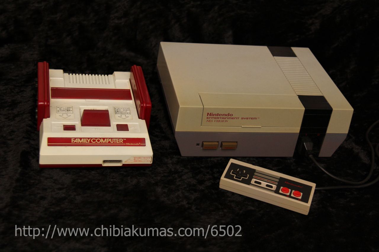
| The NES was the first games console I
owned, compared to the 8 bits I was used to (Like the CPC) it's
incredible high speed, and smooth scrolling were really impressive. While it's games tend to be limited to platformers, it's hardware was very decent for the time, and in it's later years, it's low cost made it an easy choice as a home games system. These days the main 'pulling point' for new developers is the huge number of sales the system had, and its presence in pretty much every territory, meaning that if you want to get into retro development, and get noticed, the NES or Famicom (as it was called in Japan) is a great computer to look at! The NES CPU is based on the 6502, and it's almost the same, however it has no BCD (Binary Coded Decimal) mode, however it's generally the same as the 6502 |
 |
||||||||||||||||
The UK NES PSU outputs 9V AC the Japanese Famicom PSU outputs 10V DC - CENTER NEGATIVE BE CAREFUL! adaptors that output AC are very rare and will kill most systems - and Center negative was common for 80's Japanese systems, but is very rare these days - YOU HAVE BEEN WARNED! |
ChibiAkumas Tutorials
Technical resources
Everynes documentation - Detailed documentation on the NES hardwareConsole graphics hardware - Tiles and Sprites!
This section is a general description, and not NES specific, skip to the next chapter if you know the concept of tiles and sprite layers!
| The screens on consoles usually
do not work like they do on computers like the BBC Graphics are not just 'bytes' in a memory address... The screen is made up of a 'Tile Layer' and a 'Sprite Layer' To explain Tiles and sprites, lets look at our imaginary game shown to the right 'The Super Yuusha Siblings', on a theoretical game system the 'GameChibi'... Just to be very clear, we looking at this as a concept, not the actual layout of the NES! Looking at our example, We have a level with some grass, blocks, and some collectable 'stars'... our hero, Yume is controlled by the player... |
|
| The screen is made up of the Tile
layer, and the Sprite Layer, Usually Sprites are drawn above the Tiles... but sometimes they may be drawn below. It's also possible we could use sprites for the stars.. but sprites are very limited, so the object doesn't move, then tiles will do the job... we can even animate the stars by switching the tile between different patterns |
|
| The tile array on the systems we'll
be looking at is made up of 8x8 tiles... the array is a 'grid' of
these tiles, so the tiles must line up, a block cannot be at a 'half
way boundary' Tiles are defined by a number (usually 0-255)... we define the bitmap (image) data for that tile (we'll call it a pattern), then tell the hardware what positions in the tile array to use that pattern. In our example, the black background is pattern 0 ... the blocks are pattern 1... the grass is pattern 2... and the stars are pattern 3 Our 'GameChibi' console has a tile array of 8x8... and 64 bytes is used to define the tile grid... So to define the stars, we need to set memory locations 10,20 and 15 of the tile array to byte '3' A real system usually has a tile array bigger than the screen (maybe just by one row and one column)... this is to allow smooth scrolling of the screen, where two tiles are 'half shown' Now in the case of our 'GameChibi' system, with it's 64 tile screen, and 256 pattern definitions, we could just set every visible tile to a different pattern, and treat the screen as a plain bitmap again... We can do that on the MSX1, Unfortunately, many systems do not have enough tile patterns to do this, and it's often too slow anyway... we really have to work with the system in the 'way it wants' to get good results. |
|
| Because our system is using hardware sprites, we have to design
our game sprites in a way that can be drawn with the hardware
sprites... for example lets look at our Yume sprite... if our
'GameChibi' used 8x8 hardware sprites, we would have to use 48 of
them to make this image!... we can save 6 (marked green)... these
have no data, so we can just not draw them... When it comes to moving our character, the software will have to move the hardware sprites all together, so the user does not realise they are made up of many sprites!... on systems with more onscreen colors than sprite colors, two or more sprites may be overlapped to make the sprite appear more colorful Most systems will have one color (usually 0) which marks the transparent colour. but there is a problem! with software sprites on a bitmap screen, we can draw as much as we want, it will just get slow.... but with hardware sprites, we have a fixed limit of how many sprites can be shown onscreen at once! sounds bad? well actually it's worse, even though a system like the NES can show 64 sprites onscreen, there can only be 16 on a line... if more than 16 appear on the same line, some will flicker, or not appear... there's nothing we can do about it, we just have to design our game to avoid this problem! |
The Memory Map!
| The NES memory map is a combination
of RAM, cartridge based hardware, and memory mapped registers... our
main program will start at $C000... and the first $8000 bytes of
memory are the system's 2k of ram. $2000-4020 have various 'Ports' that are used to read and write the hardware of the nes. Fortrunately the NES CPU doesn't have any real surprises for us, although it lacks the 6502's decimal mode, it is a pretty regular 6502... there's no 'Weirdness' like the PC-Engine's extra commands, and the ZeroPage is in the 'proper place' |
|
Rom Format
Nes ROMS have the following 16 header bytes:
| File Position | Bytes | Bits | Meaning | Example |
| &0000 | 4 | Header - do not change! | db "NES",$1a | |
| $0004 | 1 | Program Rom pages (16k each) | db $1 | |
| $0005 | 1 | CHR-Rom Pages (8k each) | db $0 | |
| $0006 | 1 | mmmmFTBM | mmmm =
mapper no bottom 4 bits , Four screen vram layout, Trainer at
&7000 Battery ram at &6000, Mirror (0=horiz, 1=vert) |
db %00100000 |
| $0007 | 1 | mmmm--PV | mmmm= mapper top 4 bits... Pc10 arcade, Vs unisystem | db %00000000 |
| $0008 | 1 | RAM pages (8k each) | db 0 | |
| $0009 | 7 | unused | db 0,0,0,0,0,0,0 |
The example above will give us 8k of graphics RAM via Mapper 2
The rest of our rom layout depends on the number of Program and Character rom banks we have
| Bytes | Usage |
| 16 Bytes | Header |
| 512bytes | Trainer (Usually none) |
| 16k * ? | Program ROM Banks (our code) |
| 8K * ? | Character ROM banks (pattern rom) |
Our rom file needs a header, and a 'footer' to define the vectors for the 6502... here is a sample header for a binary rom file... our code starts at $C000, so you can put everything in the correct position by starting your rom source with:
org $BFF0
db "NES",$1a ;ID
db $01 ;Rom pages (16k each)
db $0 ;CHR-ROM pages
db %00100000 ;mmmmFTBM
db %00000000 ;mmmm--PV
db 0 ;Ram pages
db 0,0,0,0,0,0,0
........................ your code here
org $FFFA
dw nmihandler, startgame, irqhandler
You will need to define labels nmihandler, irqhandler and 'startgame' (the reset vector)
PPU Graphics ports
| The PPU is the NES and Famicom's
Graphics system, it's controlled by 8 registers between $2000 and
$2007... we use these to check and set attributes of the system. and
write to VRAM (which isn't in the normal memory map!) Some of these ports take two bytes - both should be written consecutively to the same port... Strangely, when we want to write to VRAM, it's in Big Endian mode - so we have to send the High byte, then the Low byte... the opposite of the normal 6502! |
| Port | Name | Bits | Details | Notes |
| $2000 | PPUCTRL | N-SBPIAA | N=NMI
on
vblank S=Sprite size B=Back Pattern Table (0/1) P=sprite Pattern table I=Increment vram address AA=Name Table address |
I=0 means +1 , I=1 means +32 |
| $2001 | PPUMASK | CCCSBsbM | CCC=Color
emphasis B=Background on S=Sprite on s=sprite clip b=back clip M=monochrome |
s= 0 - hides leftmost 8 pixels b= 0 - hides leftmost 8 pixels |
| $2002 | PPUSTATUS | Read resets PPUSCROLL | ||
| $2003 | OAMADDR | Sprite address | (0-255) | |
| $2004 | OAMDATA | Sprite data (to write to addr, autoincs) | ||
| $2005 | PPUSCROLL | XXXXXXXX YYYYYYYYY | Select X offset and Y Offset | |
| $2006 | PPUADDR | HHHHHHHH LLLLLLLL | Select Address to write to (Big Endian!) | Write resets PPUSCROLL |
| $2007 | PPUDATA | BBBBBBBB | Byte to write to address in $2006 | |
| $A000 |
MIRROR |
-------M |
NameTable
Mirror (Some mappers only) |
M=0
Horizontal M=1 Vertical |
Vram Layout
| Specify a memory address by writing
the byte pair to $2006... HIGH BYTE FIRST... (Big Endian) NOTE: Writing to VRAM outside of VBLANK will cause problems... also note, selecting an address resets PPUSCROLL EG, lets point to $3F00... and write $11 to the first palette entry! lda #$3F ;High byte sta $2006 ;Send to vram select lda #$00 ;Low byte sta $2006 ;Send to vram select lda #$11 ;New value sta $2007 ;Send to write data |
|
Pattern Definitions for sprites and tiles
The NES has 2 pattern tables, they are selected with PPU Register $2000 Bit 4 & 3
Basic NES roms have pattern definitions in ROM (CHR-ROM), but we can use a mapper with extra video ram to make things easier - in these tutorials we'll use Mapper 2 - so we don't have to worry about CHR-ROM and can change the patterns whenever we like!
The Famicom uses bitplanes for it's data - 2 bitplanes for 4 colors... this means a tile uses 16 bytes
First we send all 8 lines of the first bitplane, Next we send all 8 lines of the second bitplane.
| Byte Data | |
| First
8 bytes Bitplane 0 |
00111100 01111111 01100011 01100011 01111111 01100011 01100011 00000000 |
| Second
8 bytes Bitplane 1 |
00222200 02222222 02200022 02200022 02222222 02200022 02200022 00000000 |
Sound, DMA and Joypad
| Address | Purpose | Bits | Detail |
| 4000h | APU Channel 1 (Rectangle) Volume/Decay (W) | CCLEVVVV | Volume, Envelope Length counter,duty Cycle |
| 4001h | APU Channel 1 (Rectangle) Sweep (W) | EUUUDSSS | Sweep, Direction,Upadte rate, Enabled |
| 4002h | APU Channel 1 (Rectangle) Frequency (W) | LLLLLLLL | frequency L byte |
| 4003h | APU Channel 1 (Rectangle) Length (W) | CCCCCHHH | frequency H byte, length Counter load register |
| 4004h | APU Channel 2 (Rectangle) Volume/Decay (W) | CCLEVVVV | Volume, Envelope Length counter,duty Cycle |
| 4005h | APU Channel 2 (Rectangle) Sweep (W) | EUUUDSSS | Sweep, Direction,Upadte rate, Enabled |
| 4006h | APU Channel 2 (Rectangle) Frequency (W) | LLLLLLLL | frequency L byte |
| 4007h | APU Channel 2 (Rectangle) Length (W) | CCCCCHHH | frequency H byte, length Counter load register |
| 4008h | APU Channel 3 (Triangle) Linear Counter (W) | SLLLLLLL | L=Linear
Counter Load S=Start |
| 4009h | APU Channel 3 (Triangle) N/A (-) | -------- |
|
| 400Ah | APU Channel 3 (Triangle) Frequency (W) | LLLLLLLL | frequency L byte |
| 400Bh | APU Channel 3 (Triangle) Length (W) | CCCCCHHH | frequency H byte, length Counter load register |
| 400Ch | APU Channel 4 (Noise) Volume/Decay (W) | CCLEVVVV | Volume, Envelope Length counter,duty Cycle |
| 400Dh | APU Channel 4 (Noise) N/A (-) | ||
| 400Eh | APU Channel 4 (Noise) Frequency (W) | N---FFFF | N=Noise
type, F=Frequency |
| 400Fh | APU Channel 4 (Noise) Length (W) | CCCCC--- | length Counter load register |
| 4010h | APU Channel 5 (DMC) Play mode and DMA frequency (W) | ||
| 4011h | APU Channel 5 (DMC) Delta counter load register (W) | ||
| 4012h | APU Channel 5 (DMC) Address load register (W) | ||
| 4013h | APU Channel 5 (DMC) Length register (W) | ||
| 4014h | SPR-RAM DMA Register (W) | HHHHHHHH |
High
byte of ram address to copy to OAM, eg $02 copies $0200-$02FF |
| 4015h | DMC/IRQ/length counter status/Sound channel enable register (RW) | DF-54321 | Dmc
irq
status / Frame irq status / Channel 12345 on (Writing resets
Frequency) |
| 4016h | Joypad #1 (RW) | ||
| 4017h | Joypad #2/APU SOFTCLK (RW) |
Joypad
The NES has 2 joysticks, but 2 extra pads can be added to the Famicom
external port... Unlike many systems, we can't read from one port to get
all the keys in one go. We need to read each button one at a time, and
build up a byte representing all the buttons in our joypad.
First we need to 'Strobe' the joypad, by writing 1 to bit $4016, then we
need to read in from $4016 and $4017 repeatedly to get all the bits of the
Joypad.
| Mode | Port | Purpose | 7 | 6 | 5 | 4 | 3 | 2 | 1 | 0 |
| Write | $4016 | Strobe (reset) | - | - | - | - | - | - | - | Strobe |
| Read | $4016 | Joypad 1/3 | - | - | - | - | - | Mic | Pad3 | Pad1 |
| Read | $4017 | Joypad 2/4 | - | - | - | - | - | - | Pad4 | Pad2 |
When we read in 8 bits from the port, we'll end up with the following byte format for our buttons:
| 7 | 6 | 5 |
4 |
3 | 2 |
1 |
0 |
| Right | Left | Down | Up | Start | Select | B | A |
Lightgun
| 7
|
6
|
5
|
4
|
3
|
2
|
1
|
0
|
Details | |
| Joystick port ($4016/7) | - | - | - | F | L | - | - | - | F=Fire (1=Yes) L=Light (0=Yes) |
Name Table for Patterns, Attribute Table for Colors
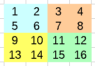
| The NES Name Table defines the
Tilemap's patterns... one byte per 8x8 tile defines the number of
the tile... the name table is 32x30 tiles in size, so spans from
$2000-$23BF Note: Name Table 2,3 ($2800-$3000) are not available on an standard NES , they will only be available if your cartridge has Extra Ram! Color's are defined by the 'Attribute table'... effectively, each square block of 2x2 tiles (16x16 pixels) have to use the same color palette... and each block of 4x4 tiles (32x32 pixels) are defined by a single byte (2 bits per block - for 4 possible palettes) Lets take the example to the right, with different 16 tiles making up a grid of 32x32 pixels- each areas palette would be defined by a single byte in the way below:
|
 |
Sprites
The NES has 64 sprites, Sprites on the NES are defined by 256 bytes of OAM memory- 4 bytes per sprite
Sprites can either be 8x8 or 8x16, when they are 8x16, the top half of the sprite is taken from the patterns at $0000, and the bottom half is taken from $1000
The byte is selected by setting the OAM-address with memory location $2003 - effectively with 4x the sprite number... then by writing the 4 bytes to $2004 (the OAM address autoincs)
The first visible pixel is at (X,Y) pos (0,8)
| Byte | Purpose | Bits | MeaningC0 |
| 1 | Ypos | YYYYYYYY |
Ypos |
| 2 | Tilenum | TTTTTTTT |
|
| 3 | Attribs | VHB---PP | Vflip Hflip Background priority Palette |
| 4 | Xpos | XXXXXXXX |
Color Palette
| The Nes palette is slightly odd
compared to RGB systems, you can see how the HEX values map to
colors in the chart to the right-> Each tile has 4 colors, and you can have 4 separate palettes for tiles... and a separate 4 for sprites... this makes a total of 32 color definitions for tiles and sprites combined |
|
| VRAM Address | Category |
| $3F00 | Common Background Color |
| $3F01 | Background Palette 0 |
| $3F05 | Background Palette 1 |
| $3F09 | Background Palette 2 |
| $3F0D | Background Palette 3 |
| $3F11 | Sprite Palette 0 |
| $3F15 | Sprite Palette 1 |
| $3F19 | Sprite Palette 2 |
| $3F1D | Sprite Palette 3 |
| View Options |
| Default Dark |
| Simple (Hide this menu) |
| Print Mode (white background) |
| Top Menu |
| ***Main Menu*** |
| Youtube channel |
| Patreon |
| Introduction to Assembly (Basics for absolute beginners) |
| Amazon Affiliate Link |
| AkuSprite Editor |
| ChibiTracker |
| Dec/Bin/Hex/Oct/Ascii Table |
| Alt Tech |
| Archive.org |
| Bitchute |
| Odysee |
| Rumble |
| DailyMotion |
| Please note: I wlll upload more content to these alt platforms based on the views they bring in |
| 68000 Content |
| ***68000 Tutorial List*** |
Learn 68000 Assembly  |
| Hello World Series |
| Platform Specific Series |
| Simple Samples |
| Grime 68000 |
| 68000 Downloads |
| 68000 Cheatsheet |
| Sources.7z |
| DevTools kit |
| 68000 Platforms |
| Amiga 500 |
| Atari ST |
| Neo Geo |
| Sega Genesis / Mega Drive |
| Sinclair QL |
| X68000 (Sharp x68k) |
| 8086 Content |
| Learn 8086 Assembly |
| Platform Specific Series |
| Hello World Series |
| Simple Samples |
| 8086 Downloads |
| 8086 Cheatsheet |
| Sources.7z |
| DevTools kit |
| 8086 Platforms |
| Wonderswan |
| MsDos |
| ARM Content |
| Learn ARM Assembly |
| Learn ARM Thumb Assembly |
| Platform Specific Series |
| Hello World |
| Simple Samples |
| ARM Downloads |
| ARM Cheatsheet |
| Sources.7z |
| DevTools kit |
| ARM Platforms |
| Gameboy Advance |
| Nintendo DS |
| Risc Os |
| Risc-V Content |
| Learn Risc-V Assembly |
| Risc-V Downloads |
| Risc-V Cheatsheet |
| Sources.7z |
| DevTools kit |
| MIPS Content |
| Learn Risc-V Assembly |
| Platform Specific Series |
| Hello World |
| Simple Samples |
| MIPS Downloads |
| MIPS Cheatsheet |
| Sources.7z |
| DevTools kit |
| MIPS Platforms |
| Playstation |
| N64 |
| PDP-11 Content |
| Learn PDP-11 Assembly |
| Platform Specific Series |
| Simple Samples |
| PDP-11 Downloads |
| PDP-11 Cheatsheet |
| Sources.7z |
| DevTools kit |
| PDP-11 Platforms |
| PDP-11 |
| UKNC |
| TMS9900 Content |
| Learn TMS9900 Assembly |
| Platform Specific Series |
| Hello World |
| TMS9900 Downloads |
| TMS9900 Cheatsheet |
| Sources.7z |
| DevTools kit |
| TMS9900 Platforms |
| Ti 99 |
| 6809 Content |
| Learn 6809 Assembly |
| Learn 6309 Assembly |
| Platform Specific Series |
| Hello World Series |
| Simple Samples |
| 6809 Downloads |
| 6809/6309 Cheatsheet |
| Sources.7z |
| DevTools kit |
| 6809 Platforms |
| Dragon 32/Tandy Coco |
| Fujitsu FM7 |
| TRS-80 Coco 3 |
| Vectrex |
| 65816 Content |
| Learn 65816 Assembly |
| Hello World |
| Simple Samples |
| 65816 Downloads |
| 65816 Cheatsheet |
| Sources.7z |
| DevTools kit |
| 65816 Platforms |
| SNES |
| eZ80 Content |
| Learn eZ80 Assembly |
| Platform Specific Series |
| eZ80 Downloads |
| eZ80 Cheatsheet |
| Sources.7z |
| DevTools kit |
| eZ80 Platforms |
| Ti84 PCE |
| IBM370 Content |
| Learn IBM370 Assembly |
| Simple Samples |
| IBM370 Downloads |
| IBM370 Cheatsheet |
| Sources.7z |
| DevTools kit |
| Super-H Content |
| Learn SH2 Assembly |
| Hello World Series |
| Simple Samples |
| SH2 Downloads |
| SH2 Cheatsheet |
| Sources.7z |
| DevTools kit |
| SH2 Platforms |
| 32x |
| Saturn |
| PowerPC Content |
| Learn PowerPC Assembly |
| Hello World Series |
| Simple Samples |
| PowerPC Downloads |
| PowerPC Cheatsheet |
| Sources.7z |
| DevTools kit |
| PowerPC Platforms |
| Gamecube |
| Work in Progress |
| ChibiAndroids |
| Misc bits |
| Ruby programming |
Buy my Assembly programming book
on Amazon in Print or Kindle!


Available worldwide!
Search 'ChibiAkumas' on
your local Amazon website!
Click here for more info!


Buy my Assembly programming book
on Amazon in Print or Kindle!
Available worldwide!
Search 'ChibiAkumas' on
your local Amazon website!
Click here for more info!
Buy my Assembly programming book
on Amazon in Print or Kindle!
Available worldwide!
Search 'ChibiAkumas' on
your local Amazon website!
Click here for more info!