

65c02 Assembly programming for the Apple IIe
| The Apple II saw many generations of
it's hardware, from the early Apple II to the final Apple IIgs the
hardware remained mostly compatible, however the hardware was
heavily upgraded, moving from a 4k 6502, to a 8mb 16 bit 65816 The most curious thing from our point of view is that the Apple II used 3 generations of the 6502, and it's the Apple IIe with its enhanced 8 bit 65C02 we'll cover in these tutorials |
 |
 |
 |
There are many versions of the Apple
2, we're only going to cover the Apple IIe in these tutorials.
|
 |
ChibiAkumas Tutorials
Useful Documents
understanding_the_apple_ii
- Great breakdown of the Apple II hardware
Understanding_the_Apple_IIe
- Apple IIe version!
Port Map - Apple II ports
Useful Tools
CiderPress - Disk
editor
| The Apple IIc memory map is pretty
typical. We'll use Graphics Mode, and Page 2 - this means for our purposes the area $0C00-$3FFF can be used for our main program code. Notice that the area $C000-$FFFF allows us to access the hardware... Each "Port" has a different purpose, but rather strangely when we want to do something like set the graphics mode, we write ANY value to the graphics port... the value makes no difference! |
|
Hardware Ports Memory Map
| Writing
any value to these memory addreses causes the hardware change. For example, to change the system to graphics mode: lda #0 sta $C050 ; Text off sta $C052 ; Mixed Mode off sta $c057 ; Display hires sta $C055 ; Hires screen 2 Reading from the ports will also have the same effect! |
|
Highres Screen - Screen Colors
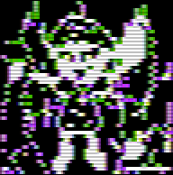
| Colors on the Apple II are effectively an 'Artifact' of the
screen... certain combinations of Off (0) and On (1) pixels will appear colored... this is known as Composite Artifact colors... Unlike pretty much every system in existance, 8 bits of a byte draw 7 pixels!.... the top bit is a 'Color bit'... selecting 'Palette 0 or 1 The remaining 7 bits are the 7 pixels of bitmap data... because each line is 40 bytes wide, the Apple II screen is a rather odd resolution of 280�192 The bits are BACKWARDS... The right pixel onscreen is the left bit (bit 6) in the byte, and the left pixel on the screen is the right pixel in the byte (bit 0) |
|
||||||||||||||||||||||||||||||||||||||
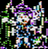
| Because of these artifacts, a '2 color' bitmap will show colors
depending on the combination of the pixels... My Akusprite editor offers a half horizontal resolution mode, where the 4 colors will be converted to the correct bit combinations |
|
||||||||||||||||||||||||||||||||||||||
Highres Screen Mode 2 -
Memory map
Memory addresses for Screen Mode 2 is
split into 3 chunks,also, every 8 lines we effectively 'reset' our
high memory address and add $80
Pixels in Each line are in normal Left->Right format, however remember 7 pixels are defined by each byte, with 1 bit defining the color palette. We can calculate the address of the start of a line by splitting the bits of the Y line number... YPOS:
Address= Base+(AA*$0028) + (BBB*$0080) + (CC*$0400) + XPOS |
|
Analog Joystick
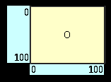
| On the Apple 2, we'll be using Analog Joysticks... these return a
value for the X and Y axis in a range of 0-100 0,0 is Top,Left.... 100,100 is Bottom,Right We're going to read these in and convert them to Digital Values |
 |
||||||||||||||||||||||||||||||||||||||||
| There are several ports we need to know about on the
Apple II Reading Analogs on the Apple II is a pain... we reset the analogs with $C070, then count up until bit 0 of $C064 (or one of the other analogs) becomes 1 - this value in our count is the analog position In thory the Apple II as 4 switches (0-3) but we can only easily use 0 and 1 Each Joystick will use Two Analogs, 0 & 1 for Joystick 1, and 2 & 3 for Joystick 2
|
|||||||||||||||||||||||||||||||||||||||||
| View Options |
| Default Dark |
| Simple (Hide this menu) |
| Print Mode (white background) |
| Top Menu |
| ***Main Menu*** |
| Youtube channel |
| Patreon |
| Introduction to Assembly (Basics for absolute beginners) |
| Amazon Affiliate Link |
| AkuSprite Editor |
| ChibiTracker |
| Dec/Bin/Hex/Oct/Ascii Table |
| Alt Tech |
| Archive.org |
| Bitchute |
| Odysee |
| Rumble |
| DailyMotion |
| Please note: I wlll upload more content to these alt platforms based on the views they bring in |
| 68000 Content |
| ***68000 Tutorial List*** |
Learn 68000 Assembly  |
| Hello World Series |
| Platform Specific Series |
| Simple Samples |
| Grime 68000 |
| 68000 Downloads |
| 68000 Cheatsheet |
| Sources.7z |
| DevTools kit |
| 68000 Platforms |
| Amiga 500 |
| Atari ST |
| Neo Geo |
| Sega Genesis / Mega Drive |
| Sinclair QL |
| X68000 (Sharp x68k) |
| 8086 Content |
| Learn 8086 Assembly |
| Platform Specific Series |
| Hello World Series |
| Simple Samples |
| 8086 Downloads |
| 8086 Cheatsheet |
| Sources.7z |
| DevTools kit |
| 8086 Platforms |
| Wonderswan |
| MsDos |
| ARM Content |
| Learn ARM Assembly |
| Learn ARM Thumb Assembly |
| Platform Specific Series |
| Hello World |
| Simple Samples |
| ARM Downloads |
| ARM Cheatsheet |
| Sources.7z |
| DevTools kit |
| ARM Platforms |
| Gameboy Advance |
| Nintendo DS |
| Risc Os |
| Risc-V Content |
| Learn Risc-V Assembly |
| Risc-V Downloads |
| Risc-V Cheatsheet |
| Sources.7z |
| DevTools kit |
| MIPS Content |
| Learn Risc-V Assembly |
| Platform Specific Series |
| Hello World |
| Simple Samples |
| MIPS Downloads |
| MIPS Cheatsheet |
| Sources.7z |
| DevTools kit |
| MIPS Platforms |
| Playstation |
| N64 |
| PDP-11 Content |
| Learn PDP-11 Assembly |
| Platform Specific Series |
| Simple Samples |
| PDP-11 Downloads |
| PDP-11 Cheatsheet |
| Sources.7z |
| DevTools kit |
| PDP-11 Platforms |
| PDP-11 |
| UKNC |
| TMS9900 Content |
| Learn TMS9900 Assembly |
| Platform Specific Series |
| Hello World |
| TMS9900 Downloads |
| TMS9900 Cheatsheet |
| Sources.7z |
| DevTools kit |
| TMS9900 Platforms |
| Ti 99 |
| 6809 Content |
| Learn 6809 Assembly |
| Learn 6309 Assembly |
| Platform Specific Series |
| Hello World Series |
| Simple Samples |
| 6809 Downloads |
| 6809/6309 Cheatsheet |
| Sources.7z |
| DevTools kit |
| 6809 Platforms |
| Dragon 32/Tandy Coco |
| Fujitsu FM7 |
| TRS-80 Coco 3 |
| Vectrex |
| 65816 Content |
| Learn 65816 Assembly |
| Hello World |
| Simple Samples |
| 65816 Downloads |
| 65816 Cheatsheet |
| Sources.7z |
| DevTools kit |
| 65816 Platforms |
| SNES |
| eZ80 Content |
| Learn eZ80 Assembly |
| Platform Specific Series |
| eZ80 Downloads |
| eZ80 Cheatsheet |
| Sources.7z |
| DevTools kit |
| eZ80 Platforms |
| Ti84 PCE |
| IBM370 Content |
| Learn IBM370 Assembly |
| Simple Samples |
| IBM370 Downloads |
| IBM370 Cheatsheet |
| Sources.7z |
| DevTools kit |
| Super-H Content |
| Learn SH2 Assembly |
| Hello World Series |
| Simple Samples |
| SH2 Downloads |
| SH2 Cheatsheet |
| Sources.7z |
| DevTools kit |
| SH2 Platforms |
| 32x |
| Saturn |
| PowerPC Content |
| Learn PowerPC Assembly |
| Hello World Series |
| Simple Samples |
| PowerPC Downloads |
| PowerPC Cheatsheet |
| Sources.7z |
| DevTools kit |
| PowerPC Platforms |
| Gamecube |
| Work in Progress |
| ChibiAndroids |
| Misc bits |
| Ruby programming |
Buy my Assembly programming book
on Amazon in Print or Kindle!


Available worldwide!
Search 'ChibiAkumas' on
your local Amazon website!
Click here for more info!


Buy my Assembly programming book
on Amazon in Print or Kindle!
Available worldwide!
Search 'ChibiAkumas' on
your local Amazon website!
Click here for more info!
Buy my Assembly programming book
on Amazon in Print or Kindle!
Available worldwide!
Search 'ChibiAkumas' on
your local Amazon website!
Click here for more info!