

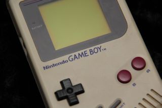
(almost) Z80 Assembly programming for the Gameboy and Gameboy Color
| The Gameboys do not use a Z80. some
people say they do, but those people are wrong! The gameboy CPU is the SM83. Like the Z80 it's based on the 8080 and is it has MANY features of a Z80, But it has some differences, and there are some hardware bugs we need to be aware of it. So why is it covered in the Z80 tutorials? Well, the gameboy+GBC sold 118 MILLION! Compared to the ZX spectrum's puny 5 million... the gamegears 10 million, the Master system's 13 million, the Gameboy gives the 'real z80' systems a spanking! We can't use a normal Z80 assembler to develop for it, but Vasm in 'OldStyle' mode will assemble code for the Gameboy processor, just use the switch '-gbz80' and it will compile compatible code! |
 |
 |
 |
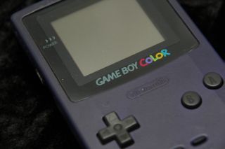
The Gameboy Color is just a Gameboy with a few 'power ups', The best thing is, if we limit ourselves a bit, we can write games that have full color on the GBC, but still play the same on the Classic Gameboy! Lets take a look at the GB and GBC specs! Specs:
|
  |
 |
If
you
want to learn GBZ80 get the Cheatsheet!
it has all the Z80 commands, but higlights the ones missing
on the GBZ80 - as well as the extra commands that the GBZ80
posesses, and the commands with different bytecode... You can use it for both your Z80 and GBZ80 development! |
 |
ChibiAkumas Tutorials
It's Z80... but not as we know it!
The first difference we'll need to know about between the Z80 and the Gameboy's 'GBZ80' (as we'll call it) CPU are the registers.
The GBZ80 has no shadow registers, and no IX and IY registers. If you're planning to port your Z80 code to Gameboy, it's best to try to avoid using these in your code (to reduce the changes you'll need to make)
| Normal Registers | Shadow Registers | |||
| Accumulator | A | A' | ||
| flags | F | F' | ||
| HighLow Memory Location | H | L | H | L |
| ByteCount | B | C | B | C |
| DEstinaton | D | E | D | E |
| Indirect X - IX | IXH | IXL | ||
| Indirect Y - IY | IYH | IYL | ||
| Program Counter | PC | |||
| Stack Pointer | SP | |||
| Refresh | R | |||
| Interrupt point | I | |||
Flags are DIFFERENT on the GBZ80!
|
Bit |
Flag |
Name |
Description |
|---|---|---|---|
|
7 |
Z |
Zero |
Zero Flag (1=zero) |
|
6 |
N |
Add / Subtract |
1=Subtract occurred, Used by DAA |
|
5 |
H |
Half Carry |
Used by DAA |
|
4 |
C |
Carry |
Carry / Borrow |
|
3 |
- |
|
|
|
2 |
- |
|
|
|
1 |
- |
|
|
|
0 |
- |
|
|
LDIR type commands are gone, but we can always fake them!
Commands that load 2 bytes from a memory address like LD BC,(&1234) do not exist, we have to read in the bytes separately
There's no IN or OUT commands, not that it matters, as devices are memory mapped, so we just read or write to them in their memory locations.
oh and thanks to a bug, INC xx and DEC xx with BC, DE or HL can corrupt the sprite memory, just for good measure!... this will occur if the regpair contains a value between $fe00-$feff . (The sprite memory)
The HALT command also has a quirk!, if interrupts are disabled, the command will skip, however the CPU also skips the following command, so put a NOP after HALT
Z80 Power Up!
Not everything has got worse though! We do have some new exciting
commands... SWAP A
will swap the top nibble and bottom nibble of A (or any other register!)
LD ($FF00+C),A ... will use C as part of the address to write to - this is the equivalent of OUT (C),a... as the memory mapped devices are in the &FF00-&FF80 range.
We also have LDI for Load and Increment, and LDD for load and decriment... it kind of makes up for losing LDIR!
There are interrupts, but there is no interrupt mode 1 or 2... RST0-7 exist, but &0038 is not called by any interrupts... GBZ80 interrupts call addresses &0040-&0060 in rom.
Console graphics hardware - Tiles and Sprites!
This section is a general description, and not Gameboy specific, skip to the next chapter if you know the concept of tiles and sprite layers!| The Gameboy,Gamegear and Mastersystem
screens do not work like they do on computers like the CPC Graphics are not just 'bytes' in a memory address... The screen is made up of a 'Tile Layer' and a 'Sprite Layer' To explain Tiles and sprites, lets look at our imaginary game shown to the right 'The Super Yuusha Siblings', on a theoretical game system the 'GameChibi'... Just to be very clear, we looking at this as a concept, not the actual layout of the gameboy! Looking at our example, We have a level with some grass, blocks, and some collectable 'stars'... our hero, Yume is controlled by the player... |
|
| The screen is made up of the Tile
layer, and the Sprite Layer, Usually Sprites are drawn above the Tiles... but sometimes they may be drawn below. It's also possible we could use sprites for the stars.. but sprites are very limited, so the object doesn't move, then tiles will do the job... we can even animate the stars by switching the tile between different patterns |
|
| The tile array on the systems we'll
be looking at is made up of 8x8 tiles... the array is a 'grid' of
these tiles, so the tiles must line up, a block cannot be at a 'half
way boundary' Tiles are defined by a number (usually 0-255)... we define the bitmap (image) data for that tile (we'll call it a pattern), then tell the hardware what positions in the tile array to use that pattern. In our example, the black background is pattern 0 ... the blocks are pattern 1... the grass is pattern 2... and the stars are pattern 3 Our 'GameChibi' console has a tile array of 8x8... and 64 bytes is used to define the tile grid... So to define the stars, we need to set memory locations 10,20 and 15 of the tile array to byte '3' A real system usually has a tile array bigger than the screen (maybe just by one row and one coumn)... this is to allow smooth scrolling of the screen, where two tiles are 'half shown' Now in the case of our 'GameChibi' system, with it's 64 tile screen, and 256 pattern definitions, we could just set every visible tile to a different pattern, and treat the screen as a plain bitmap again... We can do that on the MSX1, but unfortunately the Gameboy and Mastersystem have too few tiles for their screen size, so some parts of the screen must contain the same tile! |
|
| Because our system is using hardware sprites, we have to design
our game sprites in a way that can be drawn with the hardware
sprites... for example lets look at our Yume sprite... if our
'GameChibi' used 8x8 hardware sprites, we would have to use 48 of
them to make this image!... we can save 6 (marked green)... these
have no data, so we can just not draw them... When it comes to moving our character, the software will have to move the hardware sprites all together, so the user does not realise they are made up of many sprites!... on systems with more onscreen colors than sprite colors, two or more sprites may be overlapped to make the sprite appear more colorful Most systems will have one color (usually 0) which marks the transparent colour. but there is a problem! with software sprites on a bitmap screen, we can draw as much as we want, it will just get slow.... but with hardware sprites, we have a fixed limit of how many sprites can be shown onscreen at once! sounds bad? well actually it's worse, even though a system like the gameboy can show 40 sprites onscreen, there can only be 10 on a line... if more than 10 appear on the same line, some will flicker, or not appear... there's nothing we can do about it, we just have to design our game to avoid this problem! |
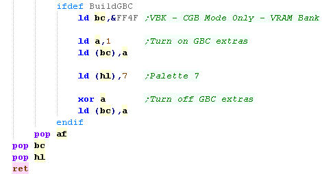
The Gameboy Color, for extra power!
| The gameboy color has many enhancements, We can switch the CPU into high speed mode, for twice the CPU power and we have extra ram banks we can page in. Most importantly the GBC adds more graphics ability, with twice the tile definitions (512) and 8 'palettes' of four colours Colour palettes are defined with a 5 bits per channel in the format -BBBBBGG GGGRRRRR Turning on the 'Second bank of tiles' (the extra 256) and setting the color palette is done by paging in the second 'GBC only' Vram Bank The second bank of the tilemap is in the format: PVH_RCCC
|
 |
Gameboy Cartridge Rom format - and Interrupt calls!
| The cartridge is loaded into the
system memory as the ROM... The first &160 bytes of the
cartridge contain the RST calls and GBZ80 Interrupt calls Next come the header, which tells the gameboy what the cartridge contains... there is also a checksum, which must be correct for the game to work on a real gameboy - though it should work on emulators without it! (the tool rgbfix.exe will work out the checksum for you!) A note on the interrupts between &0040-&0060: Interrupts can be enabled or disabled as needed, but it's best to put a 'RETI' (Return and enable interupts) at &0040-&0060 |
|
| The Rom cartridge (and its header)
take up the first &8000 bytes of memory, The 8k of ram is accessible at &C000-&DFFF... a 'shadow copy' is also at &E000-&FDFF (some cartridges have extra ram at this address) |
|
Hardware ports - AKA 'Where's my OUT command gone?'
As mentioned before, the Gameboy has no IN or Out commands, there is a bank of hardware regsiters memory mapped between &FF00 and &FF80... just write or read from these memory locations to have the hardware effect... we'll cover the details of these in later tutorials
| Section | Addr | Name | Bits | Bit Meaning | |
| Joy | FF00 | P1/JOYP - Joypad (R/W) | --BD3210 | B=Buttons D=Direction 3210=buttons DULR SSBA | |
| Serial | FF01 | SB - Serial transfer data (R/W) | 8 Bits of data | ||
| Serial | FF02 | SC - Serial Transfer Control (R/W) | S-----SC | SC - Serial Transfer Control (R/W) | |
| Timer | FF04 | DIV - Divider Register (R/W) | |||
| Timer | FF05 | TIMA - Timer counter (R/W) | |||
| Timer | FF06 | TMA - Timer Modulo (R/W) | |||
| Timer | FF07 | TAC - Timer Control (R/W) | -----SCC | S=Stary CC=Clockspeed | |
| INT | FF0F | IF - Interrupt Flag (R/W) | |||
| Sound | FF10 | NR10 - Channel 1 (Tone & Sweep) Sweep register (R/W) | -TTTDNNN | T=Time,D=direction,N=Numberof shifts | |
| Sound | FF11 | NR11 - Channel 1 (Tone & Sweep) Sound length/Wave pattern duty (R/W) | DDLLLLLL | L=Length D=Wave pattern Duty | |
| Sound | FF12 | NR12 - Channel 1 (Tone & Sweep) Volume Envelope (R/W) | VVVVDNNN | C1 Volume / Direction 0=down / envelope Number (fade speed) | |
| Sound | FF13 | NR13 - Channel 1 (Tone & Sweep) Frequency lo (Write Only) | LLLLLLLL | pitch L | |
| Sound | FF14 | NR14 - Channel 1 (Tone & Sweep) Frequency hi (R/W) | IC---HHH | C1 Initial / Counter 1=stop / pitch H | |
| Sound | FF16 | NR21 � Channel 2 (Tone) Sound Length/Wave Pattern Duty (R/W) | DDLLLLLL | L=Length D=Wave pattern Duty | |
| Sound | FF17 | NR22 - Channel 2 (Tone) Volume Envelope (R/W) | VVVVDNNN | C1 Volume / Direction 0=down / envelope Number (fade speed) | |
| Sound | FF18 | NR23 - Channel 2 (Tone) Frequency lo data (W) | LLLLLLLL | pitch L | |
| Sound | FF19 | NR24 - Channel 2 (Tone) Frequency hi data (R/W) | IC---HHH | C1 Initial / Counter 1=stop / pitch H | |
| Sound | FF1A | NR30 - Channel 3 (Wave Output) Sound on/off (R/W) | E------- | 1=on | |
| Sound | FF1B | NR31 - Channel 3 (Wave Output) Sound Length | NNNNNNNN | Higher is shorter - no effect unles C=1 in FF1E | |
| Sound | FF1C | NR32 - Channel 3 (Wave Output) Select output level (R/W) | -VV----- | VV=Volume (0=off 1=max 2=50% 3=25%) | |
| Sound | FF1D | NR33 - Channel 3 (Wave Output) Frequency's lower data (W) | LLLLLLLL | Low frequency | |
| Sound | FF1E | NR34 - Channel 3 (Wave Output) Frequency's higher data (R/W) | RC---HHH | H=high frequency C=counter repeat (loop) R=Restart sample | |
| Sound | FF20 | NR41 - Channel 4 (Noise) Sound Length (R/W) | ---LLLLL | L=Length | |
| Sound | FF21 | NR42 - Channel 4 (Noise) Volume Envelope (R/W) | VVVVDNNN | Volume / Direction 0=down / envelope Number (fade speed) | |
| Sound | FF22 | NR43 - Channel 4 (Noise) Polynomial Counter (R/W) | SSSSCDDD | Shift clock frequency (pitch) / Counter Step 0=15bit 1=7bit (sounds electronic)/ Dividing ratio (roughness) | |
| Sound | FF23 | NR44 - Channel 4 (Noise) Counter/consecutive; Inital (R/W) | IC------ | C1 Initial / Counter 1=stop | |
| Sound | FF24 | NR50 - Channel control / ON-OFF / Volume (R/W) | -LLL-RRR | Channel volume (7=loud) | |
| Sound | FF25 | NR51 - Selection of Sound output terminal (R/W) | LLLLRRRR | Channel 1-4 L / Chanel 1-4R (1=on) | |
| Sound | FF26 | NR52 - Sound on/off | A---4321 | read Channel 1-4 status or write All channels on/off (1=on) | |
| Sound | FF30 � FF3F | Wave Pattern RAM | HHHHLLLL | 32 4 bit samples | |
| LCD | FF40 | LCDC - LCD Control (R/W) | EWwBbOoD |
E=enable
screen W=Window addr (&9C00/9800) w=window display on B=Background pattern addr (&8000/8800) b=background tilemap addr (&9800/9C00) O=Object sprite size 1=8x16... o=Object Sprites enable ... D=Background display |
|
| LCD | FF41 | STAT - LCDC Status (R/W) |
|
Ly
coincidence interrupt on, Oam Interrupt on, Vblank interrupt on,
Hblank interrupt on, Coincidence flag, MM=video mode (0/1 =Vram
available) |
|
| Tile | FF42 | SCY � Tile Scroll Y | 0= default |
||
| Tile | FF43 | SCX � Tile Scroll X | 0= default | ||
| LCD | FF44 | LY - LCDC Y-Coordinate (R) - LCD Y Line (0-153 144+ are V-Blank) | |||
| LCD | FF45 | LYC - LY Compare (R/W) | |||
| RAM | FF46 | DMA - DMA Transfer and Start Address (W) | Sprite DMA -
High byte of DMA - must be executed from &FF80-FFFE |
||
| Tile | FF47 | BGP - BG Palette Data (R/W) - Non CGB Mode Only | |||
| Sprite | FF48 | OBP0 - Object Palette 0 Data (R/W) - Non CGB Mode Only | |||
| Sprite | FF49 | OBP1 - Object Palette 1 Data (R/W) - Non CGB Mode Only | |||
| Tile | FF4A | WY - Window Y Position (R/W) | |||
| Tile | FF4B | WX- Window X Position minus 7 (R/W) | |||
| CPU | FF4D | KEY1 - CGB Mode Only - Prepare Speed Switch | C------P | C=Current speed P=prepare switch | |
| VRAM | FF4F | VBK - CGB Mode Only - VRAM Bank | -------B | B=Bank | |
| COM | FF56 | RP - CGB Mode Only - Infrared Communications Port | |||
| Tile | FF68 | BCPS/BGPI - CGB Mode Only - Background Palette Index | Select
background palette byte |
||
| Tile | FF69 | BCPD/BGPD - CGB Mode Only - Background Palette Data | Write background palette byte |
||
| Sprite | FF6A | OCPS/OBPI - CGB Mode Only - Sprite Palette Index | Select sprite palette byte |
||
| Sprite | FF6B | OCPD/OBPD - CGB Mode Only - Sprite Palette Data | Write sprite palette byte |
||
| RAM | FF70 | SVBK - CGB Mode Only - WRAM Bank (bits 0-3 =0-2) | -----BBB |
BBB=Bank 1-7
(0 also pages in bank 1) |
|
| INT | FFFF | IE - Interrupt Enable (R/W) | ---JSTLV | J=Joypad S=Serial T=Timer L=Lcd stat V=vblank |
Bankswitching on cartridges with MBC1+
| Larger cartridges can have more than
32k rom, and even extra RAM built into them (With battery backup!) We switch cartridge RAM/ROM bank by writing to specific address ranges within the 'ROM'... this tells the cartridge to change bank... Good example addresses are shown below... though actually a range of addresses will have the same effect |
|
Gameboy Joystick port
| Joypad reading is all done with
memory address &FF00 Only Bits 0-3 in this address contain the state of the buttons, we first need to select which half of the joystick we want to read. If we write %11101111 to &FF00 (Bit 4 is zero) we will select the direction controls. We can then read from &FF00 to get Down, Up, Left, Right in bits 0-3 If we write %11011111 to &FF00 (Bit 5 is zero) we will select the button controls. We can then read from &FF00 will get Start, Select, Button B, Button A in bits 0-3 |
|
||||||||||||||||||||||||||||||||||||
Gameboy Sprite Memory
| Sprite Data is stored from &FE00 onwards, there are 40
sprites, and each definition uses 4 consecutive bytes... For Example, Sprite 0's bytes are highlighted in black... it has a Y co-ordinate, an X co-ordinate, a Tile Number, and tile Attributes Y and X are offset, so you can have a sprite partially off the screen, You need to set XY to (8,16) to get the top corner of the screen (0,0) Attributes:
On GBC sprites use an alternate 8 palettes to background tiles. Sprites are all 8x8 or 8x16, which is define by bit 2 of &FF40 (LCDC - LCD Control) |
||||||||||||||||
Gameboy & Gameboy Color Links
Visual Boy Advance -
Emulates the Gameboy , Gameboy Color, and others!
GameBoy Dev'rs -
Gameboy programming website
Color
Programming - The only site I can find with examples about Color on
the gameboy!
Vasm - You can't easilly
compile for the gameboy with a standard Z80 assembler like WinApe...
but VASM in 'OldStyle' mode is pretty similar to WinApe
| View Options |
| Default Dark |
| Simple (Hide this menu) |
| Print Mode (white background) |
| Top Menu |
| ***Main Menu*** |
| Youtube channel |
| Patreon |
| Introduction to Assembly (Basics for absolute beginners) |
| Amazon Affiliate Link |
| AkuSprite Editor |
| ChibiTracker |
| Dec/Bin/Hex/Oct/Ascii Table |
| Alt Tech |
| Archive.org |
| Bitchute |
| Odysee |
| Rumble |
| DailyMotion |
| Please note: I wlll upload more content to these alt platforms based on the views they bring in |
| 68000 Content |
| ***68000 Tutorial List*** |
Learn 68000 Assembly  |
| Hello World Series |
| Platform Specific Series |
| Simple Samples |
| Grime 68000 |
| 68000 Downloads |
| 68000 Cheatsheet |
| Sources.7z |
| DevTools kit |
| 68000 Platforms |
| Amiga 500 |
| Atari ST |
| Neo Geo |
| Sega Genesis / Mega Drive |
| Sinclair QL |
| X68000 (Sharp x68k) |
| 8086 Content |
| Learn 8086 Assembly |
| Platform Specific Series |
| Hello World Series |
| Simple Samples |
| 8086 Downloads |
| 8086 Cheatsheet |
| Sources.7z |
| DevTools kit |
| 8086 Platforms |
| Wonderswan |
| MsDos |
| ARM Content |
| Learn ARM Assembly |
| Learn ARM Thumb Assembly |
| Platform Specific Series |
| Hello World |
| Simple Samples |
| ARM Downloads |
| ARM Cheatsheet |
| Sources.7z |
| DevTools kit |
| ARM Platforms |
| Gameboy Advance |
| Nintendo DS |
| Risc Os |
| Risc-V Content |
| Learn Risc-V Assembly |
| Risc-V Downloads |
| Risc-V Cheatsheet |
| Sources.7z |
| DevTools kit |
| MIPS Content |
| Learn Risc-V Assembly |
| Platform Specific Series |
| Hello World |
| Simple Samples |
| MIPS Downloads |
| MIPS Cheatsheet |
| Sources.7z |
| DevTools kit |
| MIPS Platforms |
| Playstation |
| N64 |
| PDP-11 Content |
| Learn PDP-11 Assembly |
| Platform Specific Series |
| Simple Samples |
| PDP-11 Downloads |
| PDP-11 Cheatsheet |
| Sources.7z |
| DevTools kit |
| PDP-11 Platforms |
| PDP-11 |
| UKNC |
| TMS9900 Content |
| Learn TMS9900 Assembly |
| Platform Specific Series |
| Hello World |
| TMS9900 Downloads |
| TMS9900 Cheatsheet |
| Sources.7z |
| DevTools kit |
| TMS9900 Platforms |
| Ti 99 |
| 6809 Content |
| Learn 6809 Assembly |
| Learn 6309 Assembly |
| Platform Specific Series |
| Hello World Series |
| Simple Samples |
| 6809 Downloads |
| 6809/6309 Cheatsheet |
| Sources.7z |
| DevTools kit |
| 6809 Platforms |
| Dragon 32/Tandy Coco |
| Fujitsu FM7 |
| TRS-80 Coco 3 |
| Vectrex |
| 65816 Content |
| Learn 65816 Assembly |
| Hello World |
| Simple Samples |
| 65816 Downloads |
| 65816 Cheatsheet |
| Sources.7z |
| DevTools kit |
| 65816 Platforms |
| SNES |
| eZ80 Content |
| Learn eZ80 Assembly |
| Platform Specific Series |
| eZ80 Downloads |
| eZ80 Cheatsheet |
| Sources.7z |
| DevTools kit |
| eZ80 Platforms |
| Ti84 PCE |
| IBM370 Content |
| Learn IBM370 Assembly |
| Simple Samples |
| IBM370 Downloads |
| IBM370 Cheatsheet |
| Sources.7z |
| DevTools kit |
| Super-H Content |
| Learn SH2 Assembly |
| Hello World Series |
| Simple Samples |
| SH2 Downloads |
| SH2 Cheatsheet |
| Sources.7z |
| DevTools kit |
| SH2 Platforms |
| 32x |
| Saturn |
| PowerPC Content |
| Learn PowerPC Assembly |
| Hello World Series |
| Simple Samples |
| PowerPC Downloads |
| PowerPC Cheatsheet |
| Sources.7z |
| DevTools kit |
| PowerPC Platforms |
| Gamecube |
| Work in Progress |
| ChibiAndroids |
| Misc bits |
| Ruby programming |
Buy my Assembly programming book
on Amazon in Print or Kindle!


Available worldwide!
Search 'ChibiAkumas' on
your local Amazon website!
Click here for more info!


Buy my Assembly programming book
on Amazon in Print or Kindle!
Available worldwide!
Search 'ChibiAkumas' on
your local Amazon website!
Click here for more info!
Buy my Assembly programming book
on Amazon in Print or Kindle!
Available worldwide!
Search 'ChibiAkumas' on
your local Amazon website!
Click here for more info!