

Introduction to the Platform specific Series...
Its time to look a little closer at the details of the systems... lets look at how to do simple common tasks on the 6809 systems, without using the bios/firmware!


The Dragon Keyboard
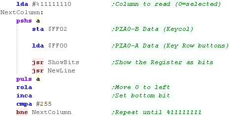
The dragon keyboard is read in one Column at a time... we select a 'column' by writing to $FF02 with byte containing zero at this point, eg PB0=%11111110
once we have done this, we read in the keys on that column from $FF00 - any key which is 'Down' will appear as 0 - keys which are not pressed appear as 1
Note, the top bit of each column is used by the joystick... also the bottom two bits are shared with the fire buttons, making it not really possible to use Joystick and keyboard at the same time.
PAx = bits read from $FF00
PBx = Write to $FF02 with byte containing zero at this point, eg
PB0=%11111110
| PB0 (W) |
PB1 (W) | PB2 (W) | PB3 (W) | PB4 (W) | PB5 (W) | PB6 (W) | PB7 (W) | |
| PA0 (R) |
0 | 1 | 2 | 3 | 4 | 5 | 6 | 7 |
| PA1 (R) | 8 | 9 | * | , | - | • | / | |
| PA2 (R) | @ | A | B | C | D | E | F | G |
| PA3 (R) | H | I | J | K | L | M | N | 0 |
| PA4 (R) | P | Q | R | S | T | U | V | W |
| PA5 (R) | X | Y | Z | Up | Down | Left | Right | Space |
| PA6 (R) | ENT | CLR | BRK | N/C | N/C | N/C | N/C | SHFT |
| PA7 (R) | JoyTest | JoyTest | JoyTest | JoyTest | JoyTest | JoyTest | JoyTest | JoyTest |
Reading in the keyboard
| To read in all the rows of the keyboard, we load A with %11111110 We send this to $FF02... and read in that column... We read the contents of that column from $FF00 we use ROLA to shift the 0 one bit to the left... reading in the next column on the next iteration of the loop |
 |
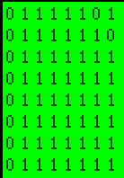
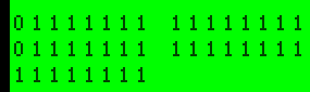
| Here is the result! Keys 8 and 1 were held down (shown in the top right)... Key '8' is bit 1 on the first line... Key '1' is bit 0 on the 2nd line the 0's on the left are the Joystick Test bits... they do not affect the keyboard |
 |
 |
if we press the
Fire button on the Left or Right joystick, bit 0 and 1 of ALL the
lines will change! This makes our keypresses unreliable, but it seems there's no way to stop it. |
The Dragon Joystick
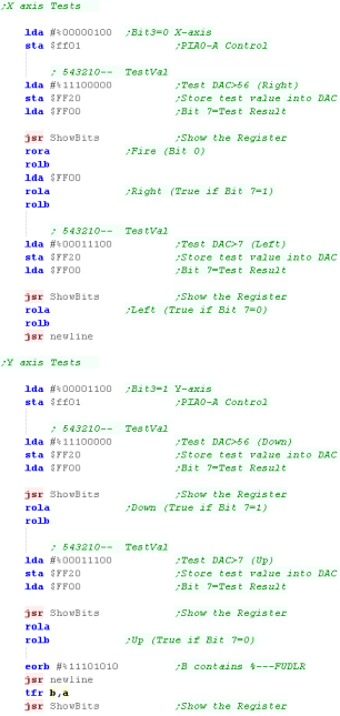
The dragon joysticks are Analog... it's also a pain!... each axis (LeftRight and UpDown) can have a position from 0-63
When we want to test an axis We write a value we want to test to the top 6 bits of $FF20 (%543210--)... we then test bit 7 of $FF00 (the keyboard port again)... 1 means the axis is OVER the test value... 0 means the axis is UNDER the test value.
In our example we simply compare to 7 and 56... if the result is <7 or >56 we consider the direction to be pressed
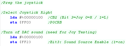
Joystick Axis selection
The DAC also handles sound, so we need to turn sound off with bit 3 of $FF23 (Bit 3=0)...
We can then select the Joystick and Axis we want to test...
We'll be testing the RIGHT joystick (Bit 3 of $FF03=0)... we select the
Axis with $FF01 Bit 3...0=X axis (LR)... 1=Y Axis (UD)
| $FF23
Bit 3 |
$FF03 Bit 3 |
$FF01 Bit 3 | |
| PIA1-CB2 | PIA0-CB2 | PIA0-CA2 | |
| SoundSource
|
Multiplexer
H |
Multiplexer
L |
Purpose |
| 0 | 0 | 0 | Write JJJJJJ-- to $FF20 .... Read ($FF00) Joystick R-X O-----LR O=1 means Over written value |
| 0 | 0 | 1 | Write JJJJJJ-- to $FF20 .... Read ($FF00) Joystick R-Y O-----LR O=1 means Over written value |
| 0 | 1 | 0 | Write JJJJJJ-- to $FF20 .... Read ($FF00) Joystick L-X O-----LR O=1 means Over written value |
| 0 | 1 | 1 | Write JJJJJJ-- to $FF20 .... Read ($FF00) Joystick L-Y O-----LR O=1 means Over written value |
Reading the Joystick
| First we need to select which joystick we're going to use with
port $FF03... we're using the Right Joystick. Next we need to turn off sound with $FF23 - we need the DAC for joystick testing |
 |
| Next we turn off the keyboard, to stop keypresses affecting the
joystick We're going to test each direction, and Fire, and move a bit for each into B |
 |
| We select an axis with bit 3 of $FF01... and compare a value
with bits 2-7 of $FF20 First we test the X axis... We compare to #56 to see if Right is pressed... the result is in bit 7 if $FF00 we move this bit into B We also get the Fire button... Bit 0 of $FF00 (Bit 1 of $FF00 is the Left Joystick fire) We compare to #7 to see if Left is pressed... the result is in bit 7 if $FF00 we move this bit into B Next we test the Y axis... We compare to #56 to see if Up is pressed... the result is in bit 7 if $FF00 we move this bit into B We compare to #7 to see if Down is pressed... the result is in bit 7 if $FF00 we move this bit into B Finally, we flip some of the bits in B... so a direction is pressed if the bit =0... The result is in the format %---FRLDU We show this to the screen. |
 |
| The bits of the 4 reads from $FF00 are shown on the first two
lines, Finally B is shown - it now contains all the buttons in the bottom 5 bits |
 |
 |
This Joystick example has shown all the
'intermediate' stages of reading the joystick... of course you'd
want to remove these! If you wanted to read the Left joystick too, you'd need to make some more changes. |
Reading the keyboard
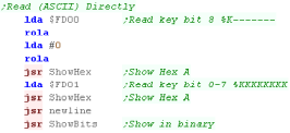
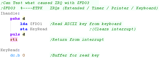
| The FM7 Keyboard is connected to BOTH cpu's... From the main CPU we can access it with port $FD01... there is an 8th bit (used by function keys) in bit 7 of $FD00 ...strangely it's also accessible from the sub CPU it's also accessible from $D400, with bit 8 in $D401 bit 0 The good news is that reading this port returns an ASCII value - the bad news is this means it seems we can't handle multiple keypresses, as there appears to be no way to directly access the keyboard matrix. |
 |
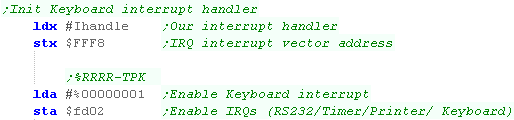
| The method above always returns the LAST keypress - even if the
keypress has long since been released. We can create an interrupt handler to detect when a key was just pressed... We load the address of our interrupt handler into the IRQ vector at $FFF8, and turn on the Keyboard interrupt with bit 0 of $FD02 The interrupt handler MUST now read from $FD01 - otherwise the keyboard interrupt will keep firing (locking our program) Here our interrupt handler will store the keypress in ram. Our main routine can read this - and then zero it, so this ram address will only hold the key WHILE it's pressed |
  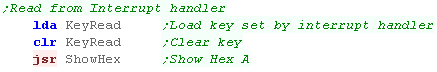 |
| In this screenshot the space key was held down (Asci 32 / $20) | 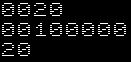 |
The FM Add on board (+Joystick)
| The FM7 didn't have a Joystick... but the later add on FM board
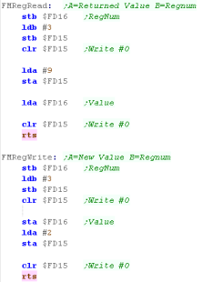
did provide one... The Joystick is connected to the AY style data ports Port A & B (Registers 14 & 15) To Read and Write from FM Registers we need to use memory mapped ports $FD15/6... these are like the AY ports, we need to send sequences of commands to port $FD15 to tell the hardware what to do with the data in $FD16 |
 |
Reading the Joystick
| We need to initialize the joystick! We need to set Port B to send data OUT - and port A to read data IN... we do this with the top two bits of Reg 7 |
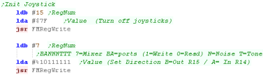 |
| We can now read in the joystick from FM reg 14... First we need to select a joystick with reg 15... Writing $2F will select Joy 1 Writing $5F will select Joy 2 Writing $7F will select Neither! the format of the byte read from R14 is %--21RLDU |
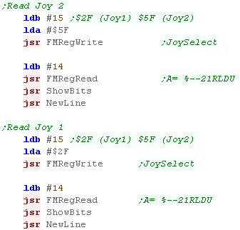 |
| Here the UP key on Joy 1 was pressed down. | 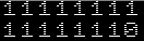 |
| The FM sound chip is
the YM2203.. you can find info on it here...The main sound chip of the FM7 is the AY-3-8910...
Actually the YM2203 is also backwards compatible with the AY! |
 |
 |
Lesson
P3 - Joystick reading on the Vectrex The Vectrex uses a 4 button Analog Joystick. In this tutorial we'll learn how to read from the joystick. |
 |
 VTX_Joystick.asm
|
 |
| The Vectrex Joystick 2 is being a moody git!... If we
try to read from it, it doesn't work, and the system locks up!... It may be the emulator doesn't support it, or the Author of these tutorials is not smart enough to make it work... Lets face it... it could be either! |
 |
Reading the Joystick
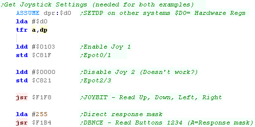
| To read the Joystick we need to make sure our direct page is set
to $D0 (hardware registers) The addresses $C81F-22 define the axis which will be read... To enable joystick 1, We write $0103 to $C81F Joystick 2 is causing problems, we turn it off by writing $0000 to $C821 We now need to get the bios to read the joystick. We read the directions with a call to $F1F8 We read the fire buttons with $F1B4 - if we set A to 255, we can get an instant response from these directions |
 |
| We can now read the Joystick X position from $C81B, and Y position
from $C81C (-64 to +64 on our emulator) We can read the state of the 4 joystick buttons from $C80F |
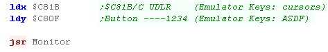 |
| Here Up, and Fire 1 were pressed... Up is represented as $40 (+64) |  |
Converting these to a single byte
| Lets convert these to a single
byte in the format %4321RLDU Note: We still need the same initialization code Here we've used 'TestOneAxis' to convert the analog values to a 1/0 direction pair We load in the fire buttons, then shift in the bits from both axis, The results are in the B register |
 |
| Here Up and Button 1 are pressed again |  |
Screen Modes
The Dragon has a variety of possible modes... the most useful being the 'Full Graphics' modes...
Selecting a screen mode requires configuring two chips... the VDG via port $FF22, and the SAM with addresses $FFC0 to $FFC5
Screenmode selection is performed by setting the top 5 bits of $FF22 and
the 3 SAM bits
Sam bits are set or cleared by writing to $FFC0-FFC5... it doesn't matter
'what' value you write... writes to Even addresses clear a bit... writes
to an odd address set a bit.
| Mode Type | G/A | GM2 | GM1 | INT /GM0 | CSS | |
SAM V2 | SAM V1 | SAM V0 | Colors | Resolution | Width in Bytes |
Screen Bytes |
Screen Mode |
| Internal Alphanumeric | 0 | ? | ? | 0 | ? | 0 | 0 | 0 | 2 color | 32x16 | 32 | 512 | Default (IA) |
|
| External Alphanumeric | 0 | ? | ? | 1 | ? | 0 | 0 | 0 | 4 color | 32x16 | 32 | 512 | ||
| Semigraphics 4 | 0 | ? | ? | 0 | ? | 0 | 0 | 0 | 8 color | 64 x 32 | 32 | 512 | (IA) |
|
| Semigraphics 6 | 0 | ? | ? | 1 | ? | 0 | 0 | 0 | 8 color | 64 x 48 | 32 | 512 | ||
| Semigraphics 8 | 0 | ? | ? | 0 | ? | 0 | 1 | 0 | 8 color | 64 x 64 | 32 | 2048 | ||
| Semigraphics 12 | 0 | ? | ? | 0 | ? | 1 | 0 | 0 | 8 color | 64 x 96 | 32 | 3072 | ||
| Semigraphics 24 | 0 | ? | ? | 0 | ? | 1 | 1 | 0 | 8 color | 64 x 192 | 32 | 6144 | ||
| Full Graphics 1C | 1 | 0 | 0 | 0 | ? | 0 | 0 | 1 | 4 color | 64 x 64 | 16 | 1024 | (D) | |
| Full Graphics 1R | 1 | 0 | 0 | 1 | ? | 0 | 0 | 1 | 2 color | 128 x 64 | 16 | 1024 | (E) | |
| Full Graphics 2C | 1 | 0 | 1 | 0 | ? | 0 | 1 | 0 | 4 color | 128 x 64 | 32 | 1536 | (F) | |
| Full Graphics 2R | 1 | 0 | 1 | 1 | ? | 0 | 1 | 1 | 2 color | 128 x 96 | 16 | 1536 | PMODE0 | |
| Full Graphics 3C | 1 | 1 | 0 | 0 | ? | 1 | 0 | 0 | 4 color | 128 x 96 | 32 | 3072 | PMODE1 | |
| Full Graphics 3R | 1 | 1 | 0 | 1 | ? | 1 | 0 | 1 | 2 color | 128 x 192 | 16 | 3072 | PMODE2 | |
| Full Graphics 6C | 1 | 1 | 1 | 0 | ? | 1 | 1 | 0 | 4 color | 128 x 192 | 32 | 6144 | PMODE3 | |
| Full Graphics 6R | 1 | 1 | 1 | 1 | ? | 1 | 1 | 0 | 2 color | 256 x 192 | 32 | 6144 | PMODE4 | |
| Direct Memory Access | ? | ? | ? | ? | ? | 1 | 1 | 1 | 2 color | 256 x 192 | 32 | 6144 | ||
| Port | $FF22 Bit 7 | $FF22 Bit 6 | $FF22 Bit 5 | $FF22 Bit 4 | $FF22 Bit 3 | 0:$FFC4 1:$FFC5 |
0:$FFC2 1:$FFC3 |
0:$FFC0 1:$FFC1 |
CSS=Color palette... ?=anything fine (Hint: Use 0)
Screen Modes
Here are all the possible screen modes... 'Unofficial' modes (not
supported by basic - D/E/F) are shown with CSS=1 (alternate colors)
Text / Semigraphics (IA) |
Full Graphics 1C (D) |
Full Graphics 1R (E) |
Full Graphics 2C (F) |
Full Graphics 2R (PMODE 0) |
Full Graphics 3C (PMODE 1) |
Full Graphics 3R (PMODE 2) |
Full Graphics 6C (PMODE 3)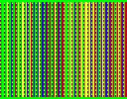 |
Full Graphics 6R (PMODE 4) |
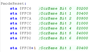
Screen Base Address
| The Top 7 bits of the Screen address can be selected by writes to
bits $FFC6-$FFD3... even addresses clear a bit, odd addresses set a
bit. Effectively the address of the screen base is:%DDDDDDD0 00000000.... where D is the bits we can change, and 0 is fixed bit zeros The example code here will reset the screen base to $0400 Writes to $FFC6-D2 set all the bits to 0... Then bit 1 is set with a write to $FFC9. |
 |
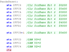
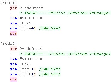
Selecting a screen mode
| To select a screen mode, we'll use some simple functions... First we'll set all the bits of the SAM to zero (and reset the screen base) with 'PmodeReset'... then we'll set the VDG bits, and any bits of the SAM we need. In the example there's one function per screen mode, just use the one for the screen mode you need. |
  |
| We can alternate the color palette by flipping the CSS bit. | 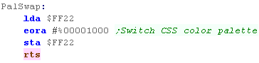 |
Creating a bitmap
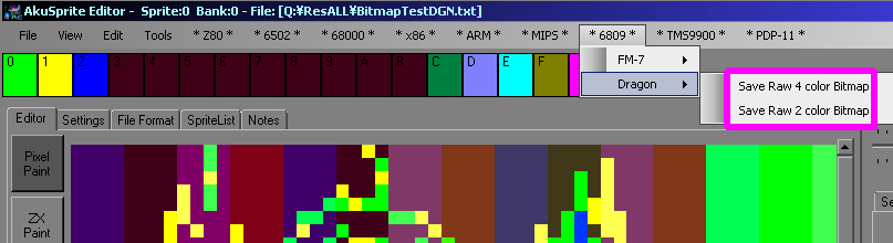
| If you want to create a bitmap
that works with this example, take a look at AkuSprite
Editor, It's free and open source, and supports ALL the systems covered by these tutorials |
 |
| Todays example works
on a wide range of screen modes!... we're only going to look at a
few here, so you'll have to download the code and try it yourself! What? you thought you could just read along, and not try it yourself???? Oh dear - you're not going to learn much like that! |
|
Drawing a bitmap
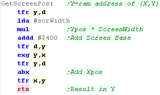
We'll need to be able to calculate the address of a position on our screen... GetScreenPos will do this! it takes an (X,Y) position in X,Y (duh!) and returns the address in Y! it's configured for a screen base of $0400, so you'll need to change it if your screen is somewhere else... The formula for the screen address is: Address = $0400 + (Ypos * Width) + Xpos Depending on our screen mode the logical Screen Width is 16 bytes or 32 bytes. |
 |
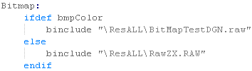
| We'll need two versions of the bitmap we want to show... a black
and white one for 2 color screens... and a 4 color one for color
screens. The format is simple, in 2 color mode, the left most bit of a byte is the left most pixel. in 4 color mode, the leftmost 2 bits are the left most pixel... other bits and pixels are represented similarly |
 |
| The sample code works on a variety of modes and color depths! we use symbols to configure the example according to the mode. |
 |
| To transfer a bitmap to the screen, we calculate the destination
(in Y) using GetScreenPos We then load our source bitmap in X, and transfer bytes to screen ram. To move down a line, we just add the width of the screen to the start address of the line. |
 |
| Try multiple screen modes and see the difference! |   |
|
The Dragon
color palettes do NOT meet the "Chibiko Seal of approval!" - there
just aren't enough purples, blacks and cyans! However, an 'unusal' color palette like this will give distinctive looking games, and adds a certain charm to the system it's fans are sure to like |
Two Cpu's are better more annoying than one
| The FM7 has two cpu's with two banks of memory and two roms!...
the MAINone runs our program... the SUB cpu is the only one that can
access graphics RAM.... how can we tell the SUB cpu what to do?
well, there's 128 bytes of 'shared ram' This Ram is accessible between $FC80-$FCFF on the main CPU. it's $D380-$D3FF on the SUB CPU... it may be a different address but it's effectively the SAME data! Both CPU's cannot access the ram at the same time... we have to HALT the Sub CPU (after WAITing for any jobs it's doing to finish) - we can then read or write data from the Main CPU... we then RELEASE the Sub CPU - it will then take over the shared ram, and try to process any commands there! |
Main CPU:
|
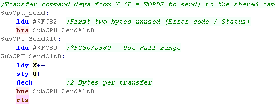
Sub CPU:
|
 |
Whenever you
resume the SUB CPU it will try to process a command in RAM at
$FC82/$D382 - if there's not one there it seems to get confused
and crash! If in doubt... you can write the dummy command $3F00 to $FC82 with... LDD #$3F00 STD $FC82 This doesn't do anything, but the Sub CPU will understand it and ignore it! |
Stopping and starting the Sub CPU with Bit7 of $FD05
| When we want to work with the SUB CPU, we can do it with bit 7 of
port $FD05 in main ram. If we want to check if the SUB CPU is Busy doing something, we can do so by testing bit 7 of $FD05 - if it's set the CPU is busy, and we should wait for it if we need the shared ram. We can test this quickly with BMI (Branch if MInus) |
 |
| If we want the MAIN CPU to access the ram, we need to Halt
the Sub CPU. First we need to wait until the Sub CPU isn't busy, then we set bit 7 of $FD05... this halts the sub CPU, we can now read or write the $FC80-$FCFF range. |
 |
| One we're done with the shared ram, we need to Release
the Sub CPU We do this by clearing bit 7 of $FD05 (writing #0) - The Sub CPU will spring into action, and try to process a command at $FC82 - so make sure you know what's written there! |
 |
|
We can't just write any old nonsense to the
shared ram, otherwise the Sub CPU will get angry! Well, actually it'll probably just crash... but we should make sure we write one of these valid commands there... we're going to take a look at some good ones, so don't worry! |
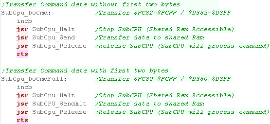
Transferring commands to the Sub CPU
| When we want to send command bytes to the Sub CPU, we'll specify
the source bytes in X, and the WORD count in B (pairs of bytes) Most GPU commands do not use the first two bytes - they start from $FC82... But a few use the full range, starting from $FC80 In either case, the number of byte varies depending on the command - but of course, there's only 128 bytes shared ram total. |
 |
| When we want to send a command there's 3 stages.. 1. Halt the Sub CPU 2. Copy the data into shared ram. 3. Resume the Sub CPU |
 |
Colors and functions
| Many of the commands take a
color number - these can be reconfigured, but the defaults are in
%GRB format. Some of the commands can use a 'Logical operation' (function) which defines how the drawn color affects any existing pixels. |
Colors:
|
Operations:
|
The Commands!
Lets start taking a look at some of the major commands, we'll learn how
they work with examples
$02=ERASE
| The Erase command ($02) uses 3 bytes... like most commands the
first 2 bytes are unused, so we write these to $FC82 There are two parameter bytes, the first isn't much use... the second is a color number |
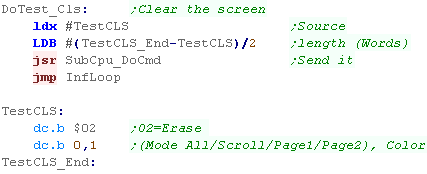 |
| We've cleared the screen to BLUE... color 1 | 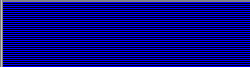 |
$17=POINTs
| the POINT command ($17) takes multiple bytes... like most commands
the first 2 bytes are unused, so we write these to $FC82 after the command is a count... this is the number of points (Max 20)... Each Point has a 16 bit Xpos and Ypos , a color , and a logical operation (0=PSET - normal draw) |
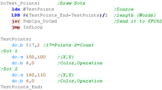 |
| We've drawn two dots onto the screen. |  |
$3=PUT
| 'Put' wll print a string to the console... Unlike many commands, this actually uses the first two bytes, so we write from $FC80... if the first byte is 0, the commands works normally - 128 will continue the last string for long texts. We specify the number of bytes to write, and we can use special console character like $12 (Locate) to do things like move the text cursor. |
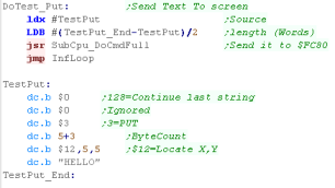 |
| We've printed HELLO at position 5,5 |  |
$19=SYMBOL
| Put can only do simple text, for snazzy stuff we want to use
SYMBOL. This command can do color, scaling and rotation (in 90 degree increments) |
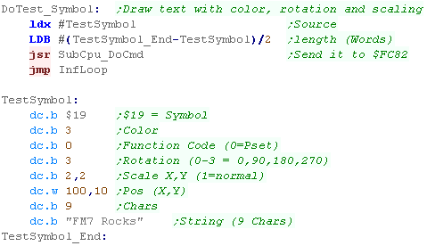 |
| We've written vertical Mangenta text! (Other colors and rotations available!) |
 |
$15=LINE
| The LINE command is misleading! Not only can it draw lines, but empty and solid filled boxes. Each commands can only draw one line/box. Here we've drawn one line and two overlapping boxes... Note we used Logical Operation 2 (XOR) |
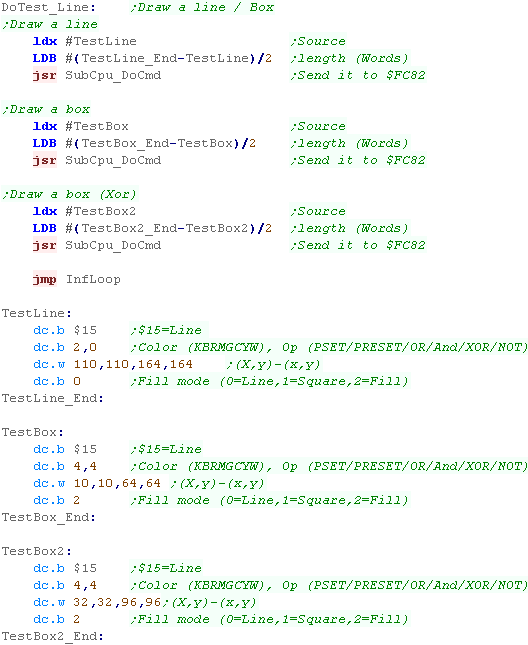 |
| We've drawn a line, and filled 2 boxes... the XOR operation has inverted the background of the boxes, causing the overlap to be blank |
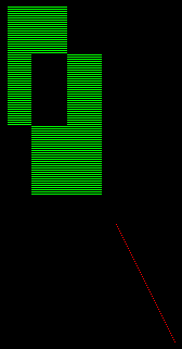 |
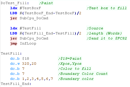
$18=PAINT
| The PAINT command will fill an area, we select a starting pixel,
and define the colors which will be treated as boundaries. In this case we've specified colors 1-7 as boundaries, so we'll only fill color 0 |
 |
| The paint command will fill the black area to the green pixel boundary (or any other color boundary!) | 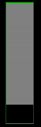 |
$1A=CHANGE COLOR
| Change color swaps one color for another. We specify a box area, and the pixels in that area will be affected. Actually we can swap multiple colors at the same time... in this example we swap 2! |
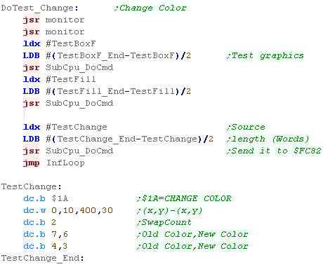 |
| We've swapped White for Yellow (7 for 6).... and also Green for Magenta (4 for 3) | 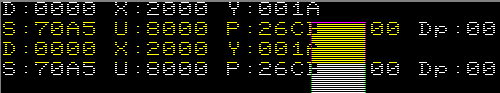 |
$29=INKEY
| The SUB CPU doesn't just write to the screen, it can also read
from the keyboard. Command $29 will read a key (it can be set to wait, or read from any pending keybuffer) once we send the command, we need to wait for it to complete, then halt the SUB CPU in the same way as when we write a command... We can then read in the Ascii character code that was read (and an extra byte, marking if a read occurred). Before we release the sub CPU we have to make sure the ram contains something that won't confuse it... we need to send the 'Ready Request' (READY REQ) - this is done by setting bit 7 of $FC80 to 1. |
 |
| here we pressed Space ($20) 1 ($31) and 2 ($32)... these can be
seen in the A register. B shows if a key was read... it contained 1 each time, as we waited for a key one was always received |
 |
| Don't forget, you can read the keyboard directly from
the Main CPU address $FD01 We looked at how to use interrupts to detect key presses before, which will be a far simpler way of doing the job. |
|
$1E=PUT BLOCK2, $64=CONTINUE
| We can transfer color bitmap data to VRAM (effectively drawing a
sprite) Because the shared ram is just 128 bytes (including command) we can only transfer about 96 bytes of sprite in a command... To get around this we first define the area with the 'Put Block 2' command... we then send more add on data with the 'Continue' command The screen data is in Bitplanes - so the image will be 48x48 repeated 3 times - First the Blue Channel, then the Red Channel, finally the Green Channel |
 |
| Our character will be shown onscreen |  |
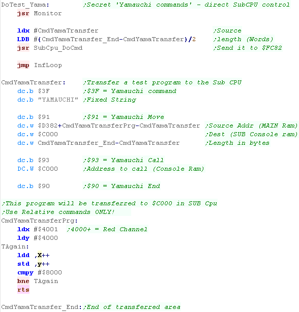
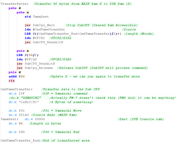
$3F,"YAMAUCHI" - The secret "Copy and Execute" command
| The Yamauchi command is a secret undocumented command within the
FM7 It allows us to transfer data from the Main CPU to a specific ram address in the SUB CPU We can also call (JSR) a specific ram address in the SUB CPU... This allows us to write arbitrary code, and run it on the SUB CPU - so we can hopefully make more efficient code that does exactly what we want! |
|
||||||||||||||||||||||||||||||
| The first bytes of the command are $3F,"YAMAUCHI" the next byte is one of 3 commands: $90 End (Yamauchi command) $91 Move (Transfer data/program) $92 Jump (Not very useful) $93 Call (JSR - run a program) Multiple commands can appear in the same 128 byte block... $3F,"YAMAUCHI" only appears at the start... so we must end with $93 Here we've transferred a program which will shift the red channel by one byte... we send it to the 'Console Ram' at $C000 in the SUB CPU, then execute it. |
 |
||||||||||||||||||||||||||||||
| We've shifted the Red channel left 1 byte with our special program! |  |
| ****By shifting
the Red channel, we've made the image into a 3d anaglph! Ok, so this is just a test, but we can now do anything we want with the ram... Actually we can alter the bitplanes, and use just 1 or 2 for the colors, and keep 1 or more free (for sprites/tiles etc)... we'll learn how soon! |
 |
| The FM8 required $3F to be followed with the 8 byte
'YAMAUCHI' string... but FM7 onwards didn't check it ... There still needs to be 8 bytes 'there' before $9x commands - but they can be anything. |
|
Palette changes
| Actually the 'color' of each bitplane is not fixed! we can change
it using addresses $FD38-$FD3F... We can set the resulting color of each combination of bits using these addresses, we cant set the brightness, we can only turn the channel on or off |
|
||||||||||||||||||||||||
| Here we're going to set all the colors to White (%00000111) then Magenta (%00000011) | 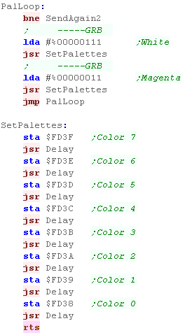 |
||||||||||||||||||||||||
| Here is the result |  |
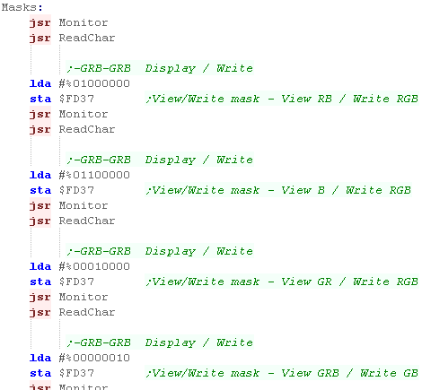
Display and Draw bitplane masks
| Actually we can disable the writing or view of some of the
bitplanes - with register $FD37 Setting a bit to 1 will Disable a plane... disabling the 'view' of the bitplane removes it's visibility... disabling the 'write' of a bitplane will not affect it's visibility, but any write operations via the graphics functions will not affect that plane. |
 |
| In this example we altered the display mask between different
channels as we showed monitors (here seen yellow)... but as they
affected all the bitplanes, they actually all wrote as white when we
enabled all the display bitplanes again When we toggled the write bitplanes, causing the text to write in different colors |
  |
|
Disclamer: The Author of these tutorials is
NOT a Vectrex expert!... while these tutorials have been written
to the best of the author's ability, limited time was available,
so they should be considered suitable for beginner use only... There are many other options and functions not covered here, and mistakes may have been made, so please do your own research and testing! |
| We're only
going to look at a small number of essential commands today...
with no word of a lie,the Vectrex has literally one hundred
trillion possible commands!... you need to look at the "Vectrex
Programming Manuals" to learn about them all. Well.. ok I might have exaggerated a little, but it does have an awful lot, and we can't cover them all here! |
|
VBLANK - Waiting for screen redraw.
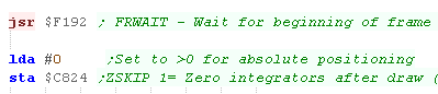
| On the vectrex we need to redraw our image every frame, to wait
for a frame we can call function $F192 (FRWAIT) we're going to set ZSKIP to zero, this affects relative drawing positions, and clearing it will ensure our code works constantly. (this example code expects it to be cleared) |
 |
Centering the drawing position
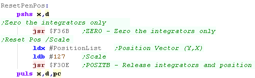
| Before each example, we want to make sure the drawing position is
centered and the scale is reset. To do this we're zeroing the 'integrators' ($F36B) that control beam position, and the 'POSITB' function ($F30E) to set the X,Y pos and scale The Vectrex uses scale #127 to mean 100%...#64 would be about 50% and #255 would be 200% The combination of these two commands should mean that the position is completely reset for any future drawing functions. |
 |
| The left image was taken with the reset occuring - Chibiko and the
smiley are near the center. On the right, Without the reset, they have become shifted by the other drawing ops |
  |
Drawing dots
| We can draw a dot with the 'DOTAB' function $F2C3, This takes a RELATIVE X,Y position and draws a dot... because it's relative, the co-ordinate is an offset from the last draw, unless we use the ResetPenPos function we wrote between draws. |
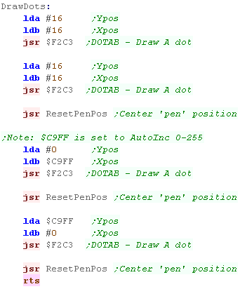 |
| We've drawn 4 dots to the screen. |  |
| These examples are
set to AutoInc $C9FF - it will constantly go up from 0-255... You can use this to test the effect of commands, in this case moving the dots in the full range. You'll notice the Y dot never reaches the top of the screen, try changing the 'Scale' in the ResetPenPos function to 255 - and see what happens! |
|
Drawing Lines
| Function call $FDF7 (DIFFAB) will draw a line from the current
selected position. We can mobe to a position with $F312 (POSITN) |
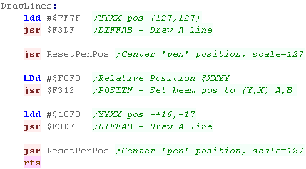 |
| We've drawn 2 lines... The co-ordinates can go from +127 ($7F) to -128 ($80 |
 |
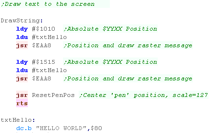
Drawing a String
 |
|
|
Here we've
looked at how to draw a single string... if you want to print
multiple strings, use function $F38C (TXTPOS)... we covered it in
the "Hello World" lesson here |
Vector images - Diffy, Duffy and Packet.
The Vectrex has three vector graphics formats!
Diffy lists are a list of connected lines
Duffy lists are an undrawn 'start position' followed by a list of
connected lines.
Packet lists are lists of lines ($FF) and undrawn movements of the pen
($00)
Below is the same graphic drawn in all 3 formats:
| Diffy | Duffy | Packet |
| dc.b 7 ;ItemCount -1 ;dc.b $00,$00 ;No initial move on Diffy dc.b $F6,$F5 ;0 Y,X Draw this dc.b $E6,$0C ;1 Y,X Draw this dc.b $FA,$F6 ;2 Y,X Draw this dc.b $F9,$0A ;3 Y,X Draw this dc.b $06,$08 ;4 Y,X Draw this dc.b $08,$F6 ;5 Y,X Draw this dc.b $17,$0E ;6 Y,X Draw this dc.b $0E,$F2 ;7 Y,X Draw this |
dc.b 8 ;ItemCount -1 dc.b $00,$00 ;0 Y,X Move to this point dc.b $F6,$F5 ;1 Y,X Draw this dc.b $E6,$0C ;2 Y,X Draw this dc.b $FA,$F6 ;3 Y,X Draw this dc.b $F9,$0A ;4 Y,X Draw this dc.b $06,$08 ;5 Y,X Draw this dc.b $08,$F6 ;6 Y,X Draw this dc.b $17,$0E ;7 Y,X Draw this dc.b $0E,$F2 ;8 Y,X Draw this |
dc.b $00,$00,$00 ;0 Y,X Move
to this point dc.b $FF,$F6,$F5 ;1 Y,X Draw this dc.b $FF,$E6,$0C ;2 Y,X Draw this dc.b $FF,$FA,$F6 ;3 Y,X Draw this dc.b $FF,$F9,$0A ;4 Y,X Draw this dc.b $FF,$06,$08 ;5 Y,X Draw this dc.b $FF,$08,$F6 ;6 Y,X Draw this dc.b $FF,$17,$0E ;7 Y,X Draw this dc.b $FF,$0E,$F2 ;8 Y,X Draw this dc.B $01 ;End of list |
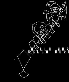
| We can draw a 'Duffy list' with $F3AD (DUFFAB) We can draw a Duffy List with a scale (at the start of the list) with $F35B (DUFFX) We can draw a Diffy list with $F3CE (DIFFAX) We can draw a Packet list with $F40E (TPACK) Here all the examples are the same 'Exclamation mark'.... 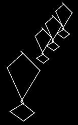 We also have a 'Chibiko example' ... (The packet list is huge - so it's not shown here!)  |
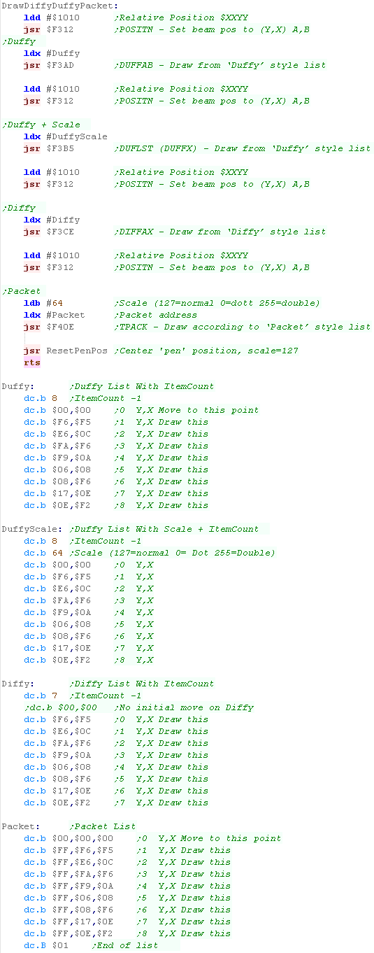 |
Rotation
| We can't specify a rotation when we show a packet list... but we
can calculate the rotation of our packet list (in rom) and
store the result in RAM We can then show that rotated packet list from ram. Here is the result!    |
 |
| We've rotated a
PACKET list, but it's also possible to rotate a DIFFY list - see
function $F616 (ADROT) |
|
|
If you want to master the AY - you'll want to
check out the AY datasheet... you can get it HERE |
Introducing ChibiSound!
| In these tutorials we're going to
create an 'amazing' new sound API to rival Directsound!!!... well at
least the functionality won't break like Directsound 3D did! Well, no it won't... what it will do is take a byte value from 0-255, and make a sound of selectable pitch, with noise or half volume in a similar way on all our systems! This was created for Grime Z80, and allows common sound code to give similar effects on all the systems! All we do is load the accumulator with a value, and call ChibiSound! Of course, this won't be enough to make music (Hint: try Arkostracker!) but it will give us some simple SFX, and make it easy to compare doing simple tasks on our various systems! |
|
Terminology!
Music sometimes uses unusual terms for simple things... here's some things you will see in sound chip documentation, and what they actually mean!
| Amplitude | Loudness |
| Envelope | How the sound changes over time (on the AY - Volume over time) |
| Mixer | Turn channels on or off |
| Noise | Distorted sounds - used for explosions, drum and symbol sounds |
| Tone | Pitch of the sound |
AY-3-8910 Registers
| The AY Sound chip is controlled by 14
internal registers that define the sounds it makes... these are
built into the chip itself, and we usually access it by 2 ports
controlled by OUT commands... one selects the register, the other
takes the new value for the register. The procedure is simple, first we send the register number to the register select port Then we send the new value to the data port. before we look at examples of how to make sounds, lets look at the way we access these ports on the systems we'll be looking at, because it's a little differe1nt on each! |
|
|
|
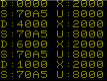
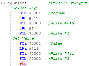
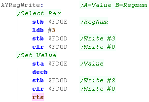
The Vectrex To Write a registers on the Vectrex we need to send a sequence of codes to port $D000, and the register Number and Value to $D001 The code here will set Reg B to Value A
|
 |
||
 |
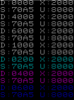
The FM7 To Write a registers of the AY on the FM7 we need to send a sequence of codes to port $FD0D, and the register Number and Value to $FD0E The code here will set Reg B to Value A
|
 |
| The FM add on
board of the FM7 is ALSO backwards compatible with the AY... it
uses different ports - take a look at the joystick example to see
how it's registers can be used. |
|
Getting the AY to work!
| If we want to do anything, we need to turn
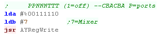
a channel on! The AY has 3 sound channels, A, B and C... rather strangely 0 turns a channel on, and 1 mutes it We turn them on using the Mixer on Reg 7... Bits 0-2 are the normal sounds for channels A-C Bits 3-5 turn noise on for channels A-C in this example, we'll turn on channel A |
 |
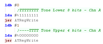
| Now we need to select a Pitch... pitches are defined by 12 bits... so each channel has two registers to define a pitch... channel A uses 0 and 1 In this example, we'll set a fairly middle tone for channel A. |
 |
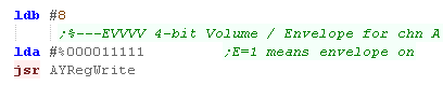
| The last thing we need to do is set a volume for channel A...
this is done with Register 8 A volume can be from 0-16... where 16 is loudest... the sound will now play! We can also turn on an envelope for the channel if we want a more complex sound... |
 |
|
Envelopes are
outside the scope of this tutorial, because the author is too
stupid to understand them properly! please see the AY sound chip PDF if you think you're brainy enough! Essentially an envelope is selected with Register 13... a speed for the envelope with 11 and 12... and it applies for any channel with the envelope bit set in that channel's volume register! |
Making the a noise!
| If we turned on noise for a channel using the Mixer a noise
element will be added to the channel... In this example we've set bit 3 to Zero... turning on noise for channel A |
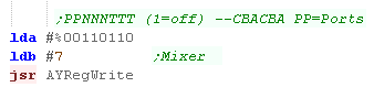 |
| All the channels share a common noise setting... to set the noise "Pitch" we use register 6... if takes a 5 bit value, which defines the noise... smaller numbers are higher pitch! |  |
Making Chibisound
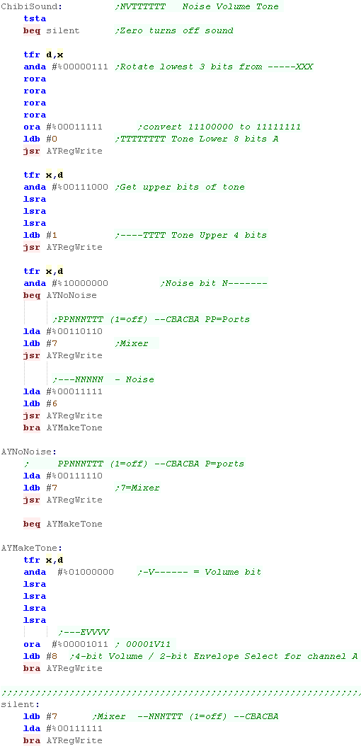
| We're now in a position to code
Chibisound! Our Accumulator byte format is %NVPPPPP where P= pitch , V = Loud volume, and N is the noise bit We use X as a backup of A while we're working, We split up PPPPP, and use some of the bits to set registers 0 and 1 (Pitch of Channel A) If N is set, we turn the noise channel on using the mixer (0=on) on register 7, then we set a noise frequency using register 6 if N is not set, we only turn on channel A using the mixer on register 7 we also need to set the volume of the channel, otherwise it won't make a sound using register 8 (volume for channel A) %00001111 is the loudest. if A is Zero... we mute all the channels using the mixer - this will stop all sounds |
 |
| Want
to learn more about the AY registers... check out this lesson here The AY can be 'Tricked' into playing digital sound samples from WAV files... want to learn how? look here |
|
Making Waves!
On the Dragon, we make sound by sending a signal to the DAC (port $FF20)
| If we alternate the signal on and off quickly, we'll make a High
pitched tone Eg: $80,$0,$80,$0,$80,$0,$80,$0 |
 |
| If we alternate the signal on and off more slowly, we'll make a
Lower pitched tone Eg: $80,$80,$0,$0,$80,$80,$0,$0 |
 |
| The higher the value sent to the DAC, the Louder the tone Eg: $FC,$FC,$0,$0,$FC,$FC,$0,$0, |
 |
| If we send erratic values we'll make a noisy tone Eg: $F0,$F0,$10,$10,$5C,$5C,$34,$34 |
 |
Controlling the hardware
To turn on the sound we have to use bit 3 of $FF23... we have to make sure
all the other bits are set correctly so we can output sound.
| $FF23
Bit 3 |
$FF21 Bit 3 |
$FF03 Bit 3 |
$FF01 Bit 3 | |
| PIA1-CB2 | PIA1-CA2 | PIA0-CB2 | PIA0-CA2 | |
| SoundSource
|
Cassette
Motor |
Multiplexer
H |
Multiplexer
L |
Purpose |
| 1 | ? | 0 | 0 | Sound: Write %SSSSSS-- to $FF20 .... 6 Bit DAC |
| 1 | ? | 0 | 1 | Cassette |
| 1 | ? | 1 | 0 | Cartridge |
| 1 | ? | 1 | 1 | Unused |
Because we need to send a constant signal, we're going to use the HSYNC IRQ - this will automatically occur frequently... we can then alter the value sent to the DAC ($FF20) to make the sound.
We turn the IRQ on with Bit 0 of $FF01
| $FF01 | PIA0-A Control | |
| Bit 7 | IRQA1: HSYNC Flag | |
| Bit 6 | IRQA2: Unused | |
| Bit 5 | 1 -> CA2 in CRA3 in bit follow mode | |
| Bit 4 | 1 -> CA2 in CRA3 in bit follow mode | |
| Bit 3 | CA2: Select Device (Multiplexor LSB) | |
| Bit 2 | Dir/Data: 0=$FF00 Selects Direction 1=$FF00 Access Data | |
| Bit 1 | CA1 ctrl: 0=IRQ on Hi to Low... 1=IRQ on Low to Hi | |
| Bit 0 | CA1 IRQ: 0=off 1=on |
When the IRQ fires, address $010C will
be called ... we will put a jump at that address to jump to our interrupt
handler.
NOTE: To clear the interrupt we must READ from $FF00 - otherwise the
interrupt will fire forever and program will crash
| Address | Vector (Address) | Registers Auto-pushed onto stack |
| $FFF2 | SWi 3 Vector ($0100) | D,X,Y,U,DP,CC |
| $FFF4 | SWI 2 Vector ($0103) | D,X,Y,U,DP,CC |
| $FFF6 | FIRQ Vector ($010F) | D,X,Y,U,DP,CC |
| $FFF8 | IRQ Vector ($010C) | CC |
| $FFFA | SWI 1 Vector ($0106) | D,X,Y,U,DP,CC |
| $FFFC | NMI Vector ($0109) | D,X,Y,U,DP,CC |
| $FFFE | RESET Vector ($B3B4) | NA |
|
Because we're using an interrupt, our program
can run as usual and the sound will still play... but of course
the interrupt handler will be using up some CPU power |
| All the
interrupts except IRQ and Reset push all the registers onto the
stack automatically... That means we don't have to worry about changing them while the interrupt handler runs... To save time, Fast IRQ (FIRQ) does not... and it makes no sense for RESET! |
|
Introducing ChibiSound!
| In these tutorials we're going to
create an 'amazing' new sound API to rival Directsound!!!... well at
least the functionality won't break like Directsound 3D did! Well, no it won't... what it will do is take a byte value from 0-255, and make a sound of selectable pitch, with noise or half volume in a similar way on all our systems! This was created for Grime Z80, and allows common sound code to give similar effects on all the systems! All we do is load the accumulator with a value, and call ChibiSound! Of course, this won't be enough to make music (Hint: try Arkostracker!) but it will give us some simple SFX, and make it easy to compare doing simple tasks on our various systems! |
|
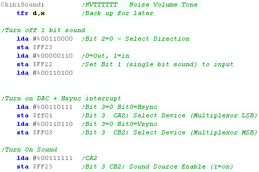
Writing ChibiSound
| First we need to set up the PIA's to enable sound, and the Hsync
interrupt. We also turn off 'single bit' sound by setting it's bit to INPUT (we're using 6 bit sound!) |
 |
||||
| We're going to need some temp vars for the sound - we pass the interrupt handler the settings here | 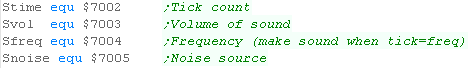 |
||||
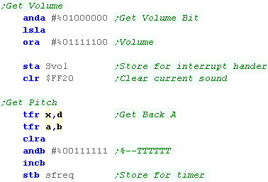
| We use the 6 bits of pitch of our parameter to calculate the
'speed' we need to alternate the tone. The parameter only has 1 bit of volume - we use this to build the 6 bit 'volume mask' we'll use to alternate the waveform in the interrupt handler |
 |
||||
| Depending on if we're making a noise or a tone we'll use a different interrupt handler. | 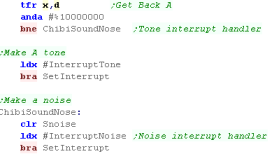 |
||||
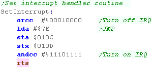
| Ok! We want to set our interrupt handler... First we set bit 4 of the CC register - this stops interrupts while we're messing! Next we change the interrupt handler at $010C... we write $7E (a JMP command) and the address of our interrupt handler now we clear bit 4 of the CC register - this starts the interrupt handler - so we'd better be ready! |
 |
||||
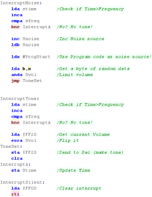
| We have two interrupt handers... Both use the 'Stime' counter - this increases until it reaches Sfreq... at which point we alter the sound level in the top 6 bits of $FF20 (The volume of the wave)... we then zero Stime. This has the effect that the lower Sfreq is, the higher pitch the sound
If we're making a normal 'Tone' we just flip the wave (eg between 0 and $FC) If we're making a noise, we need to send random(ish) values - we get these from the first 255 bytes of our source code! To make the IRQ read (and stop it immediately re-firing) we have to read from $FF00 |
 |

Setting up the screen
| First, Let's turn on the FAST CPU mode... we just write to port
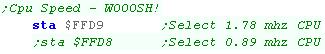
$FFD9 (it doesn't matter what)... this turns on 1.78 mhz mode on! If we can't handle the awesome speed of the 6809, we can turn back to regular 0.89 mhz by writing to $FFD8 |
 |
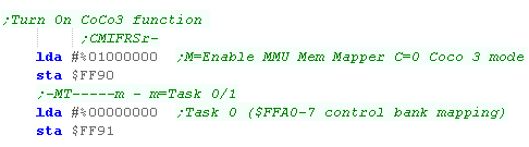
| We need to turn on the Coco 3 features... We turn on the MMU (Extra ram) with bit 6 of $FF90... Bit 7 disables Coco1/2 compatibility We select 'Task 0' (Executive mode) of the MMU with bit 0 of $FF91... this sets up things so ports $FFA0-7 control the banks of addressable ram (We only use $FFA1 to control the $2000-$3FFF range) |
 |
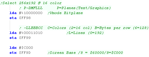
| We want to select a graphics mode! We turn graphics on with bit 7 of $FF98 We select our mode with $FF99 - we're selecting 16 color, 128 bytes per row, 192 lines (256x192 @ 16 color) We select the screen base address with $FF9D/E... we want to use address $60000, but we need to divide by 8 ($C000) and store the result in this address. |
 |
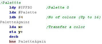
| We want to set up a palette!... this uses the 16 addresses from
$FFB0+ Each color uses 6 bits of 1 byte in the format %--RGBRGB... bits 3-5 are the High bit, bit 0-2 are the Low bit |
  |
Using our Screen
| Our screen uses a total of 24k - from physical address
$60000-$65FFF (Pages $30-32) We'll page these in to the $2000-$3FFF range using $FFA1 as required to draw each line of our graphic |
|
||||||||||||
| Each line of our screen is 128 bytes, Because each page of our screen holds 64 lines, we can strip off the top 2 bits of our Y address for the bank number (%BBYYYYYY) - our first bank is $30 the remaining 6 Y bits %--YYYYYY * 128 is the offset in that bank over all our formulas are: $FFA1 = $30 + YY (where YY= %YY--------) DestAddr = $2000 + YYYYYY * 128 + Xpos (Where YY= %--YYYYYY) |
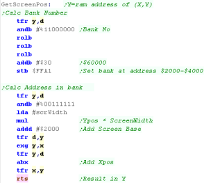 |
||||||||||||
| When we need to move down a line, we add 128 If our memory pointer (Y) has gone over $4000 - we need to page in the next bank, and reset it to $2000 |
 |
||||||||||||
| We can use these functions to transfer a bitmap from our program ram to VRAM - GetScreenPos and GetNextLine automatically handle the bankswitching! | 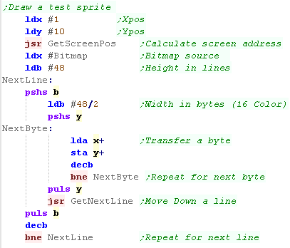 |
||||||||||||
| We've drawn our Chibiko mascot to the screen! |  |
| Of course the CoCo 3 supports a wide range of screen
sizes and color options, we've just tried the most 'interesting'
here. If you want to use a different one in your code, you'll need to tweak the calculations of screen memory positions accordingly. |
|
| You can export sprites in the correct format for this tutorial with my AkuSprite Editor, it's included in the sources.7z | 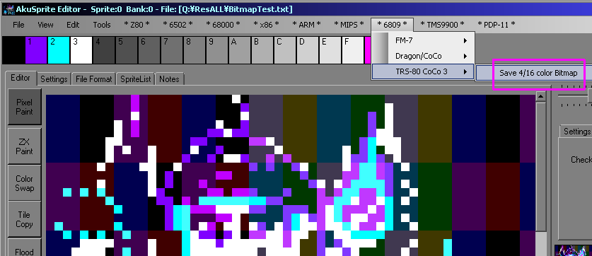 |
|
Last time we
said the 'Yamauchi' command needed the "YAMAUCHI" string as a
password to make the command work - on the earlier FM8 that was
true - but the FM7 / FM77 do not check the string - there needs to
be 8 unused bytes, but they can be anything! |
Tiles!
| We're going to create an 8x8 tile routine... we'll transfer it to
VRAM, then we'll call that routine to repeatedly draw tiles until
the screen is full. Because the Sub CPU is drawing all the tiles, the Main CPU will be able to do anything we want at the same time. In a real game, we'd probably want to create a 'list' of tile sources and screen destinations to draw the updates to our screen as the gameplay progresses. |
 |
2 CPUs = Double Trouble.
| The FM7 has two cpu's with two banks of memory and two roms!...
the MAIN one runs our program... the SUB cpu is the only one that
can access graphics RAM.... how can we tell the SUB cpu what to do?
well, there's 128 bytes of 'shared ram' This Ram is accessible between $FC80-$FCFF on the main CPU. it's $D380-$D3FF on the SUB CPU... it may be a different address but it's effectively the SAME data! Both CPU's cannot access the ram at the same time... we have to HALT the Sub CPU (after WAITing for any jobs it's doing to finish) - we can then read or write data from the Main CPU... we then RELEASE the Sub CPU - it will then take over the shared ram, and try to process any commands there! |
Main CPU:
|
Sub CPU:
|
|
Whenever you
resume the SUB CPU it will try to process a command in RAM at
$FC82/$D382 - if there's not one there it seems to get confused
and crash! If in doubt... you can write the dummy command $3F00 to $FC82 with... LDD #$3F00 STD $FC82 This doesn't do anything, but the Sub CPU will understand it and ignore it! |
Stopping and starting the Sub CPU with Bit7 of $FD05
| When we want to work with the SUB CPU, we can do it with bit 7 of
port $FD05 in main ram. If we want to check if the SUB CPU is Busy doing something, we can do so by testing bit 7 of $FD05 - if it's set the CPU is busy, and we should wait for it if we need the shared ram. We can test this quickly with BMI (Branch if MInus) |
|
| If we want the MAIN CPU to access the ram, we need to Halt
the Sub CPU. First we need to wait until the Sub CPU isn't busy, then we set bit 7 of $FD05... this halts the sub CPU, we can now read or write the $FC80-$FCFF range. |
|
| One we're done with the shared ram, we need to Release
the Sub CPU We do this by clearing bit 7 of $FD05 (writing #0) - The Sub CPU will spring into action, and try to process a command at $FC82 - so make sure you know what's written there! |
|
|
We can't just write any old nonsense to the
shared ram, otherwise the Sub CPU will get angry! Well, actually it'll probably just crash... but we should make sure we write one of these valid commands there... we're going to take a look at some good ones, so don't worry! |
Transferring commands to the Sub CPU
| When we want to send command bytes to the Sub CPU, we'll specify
the source bytes in X, and the WORD count in B (pairs of bytes) Most GPU commands do not use the first two bytes - they start from $FC82... But a few use the full range, starting from $FC80 In either case, the number of byte varies depending on the command - but of course, there's only 128 bytes shared ram total. |
|
| When we want to send a command there's 3 stages.. 1. Halt the Sub CPU 2. Copy the data into shared ram. 3. Resume the Sub CPU |
|
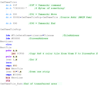
A quick 96 byte transfer command.
| We're going to create a command that uses command $91 - Yamauchi
Move to transfer data from the main CPU to the sub CPU This command will simplify it's use, and will transfer 96 bytes of data from the address in main CPU ram in register X to the address in sub CPU ram in register D Because the transfer window is just 128 bytes - 96 bytes is about the most we can do per run of this command - but we can run the command multiple times to transfer more data. |
 |
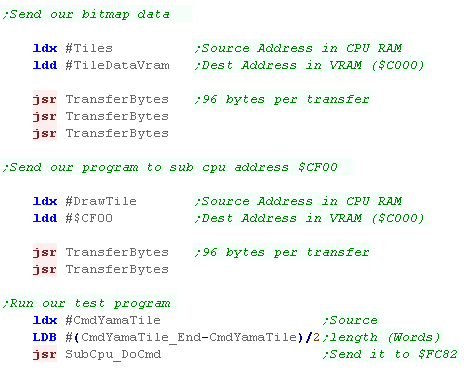
| Here we're using the routine to transfer our Tiles (TILES) from
Cpu RAM to VRAM - these are the sprites we'll use We're also transferring the sprite drawing program (DRAWTILE) to VRAM - we load it to address $CF00 Finally we need to run our Tile drawing program with "CmdYamaTile" |
 |
Tile Drawing
| Here is our drawtile routine. This will copy 8x8 4 color tile from
Vram U to ScreenPos X We load in byte pairs from U... this gives us enough data to fill 2 lines of one bitplane. Each line of the screen is 80 bytes wide, so we add 80*Linenumber to the address in X Once we've done the first bit plane we add $4000 to move to the 2nd bitplane, and $8000 to move to the 3rd bitplane (if needed) |
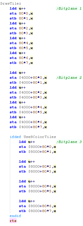 |
| We need to use transfer a small program to use DrawTile Here' we using it to repeatedly draw tiles to fill the screen. |
 |
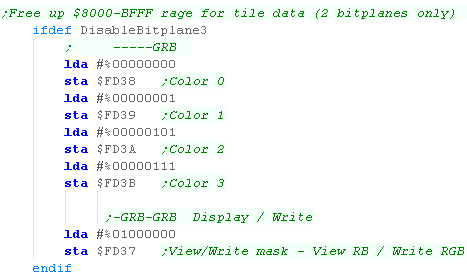
Disabling bitplane 3 - to free up 16k of vram for sprites
| If we only want a 4 color screen, we can disable one of the
bitplanes... this frees up VRAM for sprite data. Usually there's only $1000 bytes or so free for our sprites - but doing this gives us $5000 bytes. |
 |
| View Options |
| Default Dark |
| Simple (Hide this menu) |
| Print Mode (white background) |
| Top Menu |
| ***Main Menu*** |
| Youtube channel |
| Patreon |
| Introduction to Assembly (Basics for absolute beginners) |
| Amazon Affiliate Link |
| AkuSprite Editor |
| ChibiTracker |
| Dec/Bin/Hex/Oct/Ascii Table |
| Alt Tech |
| Archive.org |
| Bitchute |
| Odysee |
| Rumble |
| DailyMotion |
| Please note: I wlll upload more content to these alt platforms based on the views they bring in |
| 68000 Content |
| ***68000 Tutorial List*** |
Learn 68000 Assembly  |
| Hello World Series |
| Platform Specific Series |
| Simple Samples |
| Grime 68000 |
| 68000 Downloads |
| 68000 Cheatsheet |
| Sources.7z |
| DevTools kit |
| 68000 Platforms |
| Amiga 500 |
| Atari ST |
| Neo Geo |
| Sega Genesis / Mega Drive |
| Sinclair QL |
| X68000 (Sharp x68k) |
| 8086 Content |
| Learn 8086 Assembly |
| Platform Specific Series |
| Hello World Series |
| Simple Samples |
| 8086 Downloads |
| 8086 Cheatsheet |
| Sources.7z |
| DevTools kit |
| 8086 Platforms |
| Wonderswan |
| MsDos |
| ARM Content |
| Learn ARM Assembly |
| Learn ARM Thumb Assembly |
| Platform Specific Series |
| Hello World |
| Simple Samples |
| ARM Downloads |
| ARM Cheatsheet |
| Sources.7z |
| DevTools kit |
| ARM Platforms |
| Gameboy Advance |
| Nintendo DS |
| Risc Os |
| Risc-V Content |
| Learn Risc-V Assembly |
| Risc-V Downloads |
| Risc-V Cheatsheet |
| Sources.7z |
| DevTools kit |
| MIPS Content |
| Learn Risc-V Assembly |
| Platform Specific Series |
| Hello World |
| Simple Samples |
| MIPS Downloads |
| MIPS Cheatsheet |
| Sources.7z |
| DevTools kit |
| MIPS Platforms |
| Playstation |
| N64 |
| PDP-11 Content |
| Learn PDP-11 Assembly |
| Platform Specific Series |
| Simple Samples |
| PDP-11 Downloads |
| PDP-11 Cheatsheet |
| Sources.7z |
| DevTools kit |
| PDP-11 Platforms |
| PDP-11 |
| UKNC |
| TMS9900 Content |
| Learn TMS9900 Assembly |
| Platform Specific Series |
| Hello World |
| TMS9900 Downloads |
| TMS9900 Cheatsheet |
| Sources.7z |
| DevTools kit |
| TMS9900 Platforms |
| Ti 99 |
| 6809 Content |
| Learn 6809 Assembly |
| Learn 6309 Assembly |
| Platform Specific Series |
| Hello World Series |
| Simple Samples |
| 6809 Downloads |
| 6809/6309 Cheatsheet |
| Sources.7z |
| DevTools kit |
| 6809 Platforms |
| Dragon 32/Tandy Coco |
| Fujitsu FM7 |
| TRS-80 Coco 3 |
| Vectrex |
| 65816 Content |
| Learn 65816 Assembly |
| Hello World |
| Simple Samples |
| 65816 Downloads |
| 65816 Cheatsheet |
| Sources.7z |
| DevTools kit |
| 65816 Platforms |
| SNES |
| eZ80 Content |
| Learn eZ80 Assembly |
| Platform Specific Series |
| eZ80 Downloads |
| eZ80 Cheatsheet |
| Sources.7z |
| DevTools kit |
| eZ80 Platforms |
| Ti84 PCE |
| IBM370 Content |
| Learn IBM370 Assembly |
| Simple Samples |
| IBM370 Downloads |
| IBM370 Cheatsheet |
| Sources.7z |
| DevTools kit |
| Super-H Content |
| Learn SH2 Assembly |
| Hello World Series |
| Simple Samples |
| SH2 Downloads |
| SH2 Cheatsheet |
| Sources.7z |
| DevTools kit |
| SH2 Platforms |
| 32x |
| Saturn |
| PowerPC Content |
| Learn PowerPC Assembly |
| Hello World Series |
| Simple Samples |
| PowerPC Downloads |
| PowerPC Cheatsheet |
| Sources.7z |
| DevTools kit |
| PowerPC Platforms |
| Gamecube |
| Work in Progress |
| ChibiAndroids |
| Misc bits |
| Ruby programming |
Buy my Assembly programming book
on Amazon in Print or Kindle!


Available worldwide!
Search 'ChibiAkumas' on
your local Amazon website!
Click here for more info!


Buy my Assembly programming book
on Amazon in Print or Kindle!
Available worldwide!
Search 'ChibiAkumas' on
your local Amazon website!
Click here for more info!
Buy my Assembly programming book
on Amazon in Print or Kindle!
Available worldwide!
Search 'ChibiAkumas' on
your local Amazon website!
Click here for more info!