

TI-99
Platform Specific Series
<- Back to the Main
Contents & Basic TMS9900 Assembly Lessons
Introduction to the Platform Specific Series...
In this series we'll be looking at examples that use the TI-99 hardware.
Introduction to the Platform Specific Series...
In this series we'll be looking at examples that use the TI-99 hardware.


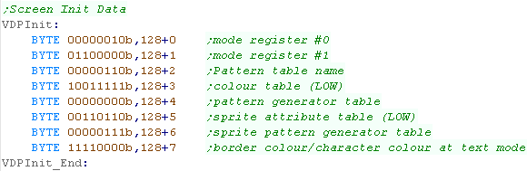
| The TMS9918 VDP memory works
differently depending on the screenmode, but today we'll be using it
in this setup. We need to define Tile Patterns for our Font and Chibiko bitmap, set colors in the Colormap, and define the Tilemap to get them showing onscreen. Patterns are just 1bpp... so 2 color... colors are defined by the Pixel Line... not tile, so each 8x8 tile has 8 color lines... each a single byte containing a foreground and background color (&FB) |
|
| Notice
the
weird 'gap' between &800 and &17FF?.. well the VDP can
have two extra sets of pattern definitions... although the MSX1
always uses a tilenumber between 0-255, the screen can split into
3 'thirds'... each third will use a separate tilemap (the 2nd at
&800 and 3rd at &1000)... this is how we faked a bitmap
mode before! I suppose if you wanted to have your UI in the bottom third (with font definitions and lives etc)... and the top two thirds the playing area (with common tile definitions?) it would work quite nicely! |
 |
| In this example we're going to show a
Chibiko bitmap... This image is 48x48 split into 8x8 tiles |
 |
||||||||||||||||
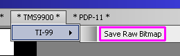
| We can create the bitmap data using
my 'AkuSprite' editor (included in Sources.7z)... For this example
you want to use 'TI99
-> Save RAW Bitmap' This will export the bitmap as a black and white bitmap in the correct order for the VDP's tilemap ... |
 |
||||||||||||||||
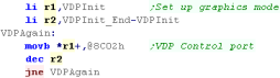
| We need to initialize our screen, we need to set the VDP control
registers, buy writing bytes to the VDP control port... The first byte is the new value... the second byte is the register number + 128 (bit 7=1) |
  |
||||||||||||||||
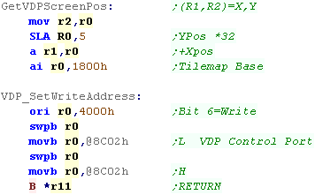
| We have to set up the VDP's registers
so that when we out data to the VDP it will be written to memory. We do this by writing the R0 memory address to the Control port... we add 4000h to the address to tell the VDP we want to WRITE not read data. We also have a 'GetVdpScreenPos function' this calculates the Vram tile pos from an X,Y position. Each line is 32 tiles - so we multiply the Ypos by 32 We then add the tilemap base 1800h |
 |
||||||||||||||||
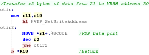
| We're defining a command for bulk transfer called OTIR... this
will transfer a sequence of bytes to VRAM (OTIR is OutIncRepeat from the Z80 command set) |
 |
||||||||||||||||
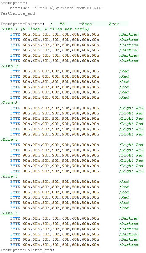
| We import our Bitmap data, and have our color data defined as
bytes - each tile needs 8 bytes - and each 'horizontal strip' is 6
tiles. Color can be set for each 8x1 pixel area (8 pixels wide, 1 line)... Color definitions start at memory address 2000h... the 8 lines of color definitions for each 8x8 block are lumped together, so we separate out the last 3 bits of C, and add them last. Each byte defines a foreground and background color... foreground in the first nibble, background in the second... &FB The color palette is fixed, and there are no brightness or other limitations (unlike the speccy!)
|
 |
||||||||||||||||
| We have our bitmap data and color data to transfer to VRAM... we use OTIR to transfer the bitmap and color data. | 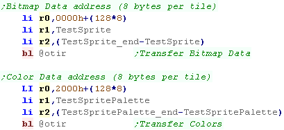 |
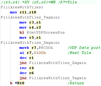
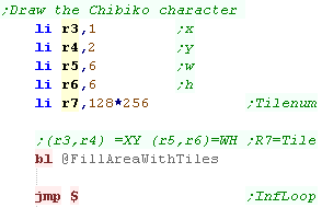
| When we want to draw the Chibiko
bitmap, we will use the 'FillAreaWithTiles function... this
takes an XY position in R3,R4, a Width and Height in R5,R6, and a
start tile number in R7... The effect of this routine is to build the chibiko character out of tiles.
|
  |
||||||||||||||||||||||||||||||||||||||||||||||||||||||||||||||||||||||||||||||||||||||||||
| Here is the result. | |
 |
The TMS9900's color
graphics are rather odd really, as it uses as much data for the
color map as the bitmap... if you want to see it used 'properly'
please take a look at the Grime
Z80 project... which has line level color info for it's
tiles... of course you can always cheat, and set all 8 lines of a tile to the same color, like ZX spectrum color attributes! |
| The
TMS9900 can also do hardware sprites, but we're not covering
them here. |
 |
TI Key Map
To select a column of the Keymap we use CRU
Address 0024h, we can then read in from the address 0006h
We can read a whole column into R4 with ST
R4,8
We can test a single bit with TB n - where n
is the bit (offset from 0006h) to test
| CRU Address | Col 0 | Col 1 | Col 2 | Col 3 | Col 4 | Col 5 | Col 6 | Col 7 | Bit |
| 0006h | = | . | , | M | N | / | J1-Fire | J2-Fire | 0 |
| 0008h | space | L | K | J | H | ; | J1-Right | J2-Right | 1 |
| 000Ah | enter | O | I | U | Y | P | J1-Left | J2-Left | 2 |
| 000Ch | 9 | 8 | 7 | 6 | 0 | J1-Down | J2-Down | 3 | |
| 000Eh | fctn | 2 | 3 | 4 | 5 | 1 | J1-Up | J2-Up | 4 |
| 0010h | shift | S | D | F | G | A | 5 | ||
| 0012h | ctrl | W | E | R | T | Q | 6 | ||
| 0014h | X | C | V | B | Z | 7 |
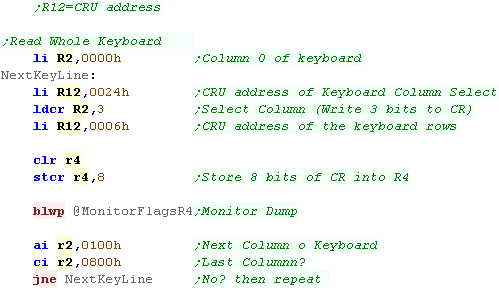
Reading a whole column of the keyboard
| R12 is used to select the CRU address... First we select address 0024h - we use this to select the column we want to read. We transfer a column number (0-7) with LDCR - we need to transfer 3 bits. Now we need to select the start of the keyboard rows... 0006h We can now transfer 8 bits to a register with STCR - this read an entire column of the keyboard into that register. |
 |
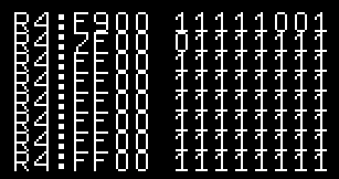
| The example here reads each column, showing it to the screen as
hex and binary. In this example Space,Enter and X are held down.. Space and Enter are shown on the top line as 0 (2,3 bits of Col 0) ... X is on the 2nd line (7th bit of Col 1) |
 |
Testing a single button of the Joystick
| Rather than read the whole column, maybe we just want to test one
button, for example if we want to check if Joy1 Up is pressed. As before, we select a column of the keyboard with R2 (Column 6 - Joy 1) We transfer this to the Keyboard column select with address 0024h We then select the address 0006 again... This time rather than using STCR, we test bits of the CRU data with TB... in this case we test bit 4... since we selected Column 6 - this tests UP |
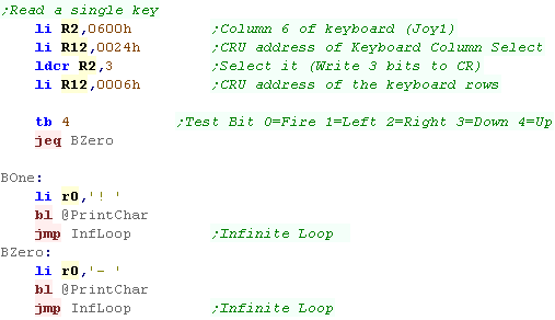 |
| This example will show an ! when UP is pressed. |  |
 |
The CRU is a bit weird - it can only use
register R12 - and it has special commands and it's own address
space... it's used by the keyboard and a few other bits of
hardware... but strangely not for the VDP or sound chip - which
are memory mapped... therefor we won't actually need it much. |
Basics of the TMS9919
The sound chip takes all its data from a
single 8 bit port... at memory mapped address 8400h
The 7th bit is the 'latch bit' which tells the chip if a new command is being sent (1) or a second part of the last command (0)
Bits 6 and 5 are the channel number... 0-2 are tone chanels, 4 is the noise channel
Bit 4 is the 'Type bit'... 0 defines the sound... 1 defines the Volume
The purpose of the remaining bits (0-3) vary depending on the first 4
| Bits | |||||||||
| Command | Bit Details | 7 | 6 | 5 | 4 | 3 | 2 | 1 | 0 |
| Format Template | L=Latch C=Channel T=Type XXXX=Data | L | C | C | T | D | D | D | D |
| Tone - Command 1/2 | C=Channel L=tone Low data | 1 | C | C | 0 | L | L | L | L |
| Tone - Command 2/2 | H= High tone data (Higher numbers = lower tone) | 0 | - | H | H | H | H | H | H |
| Volume | C=Channel (0-2) V=Volume (15=silent 0=max) | 1 | C | C | 1 | V | V | V | V |
| Noise Channel | (Channel 3) M=Noise mode (1=white) R=Rate (3=use tone 2) | 1 | 1 | 1 | 0 | - | M | R | R |
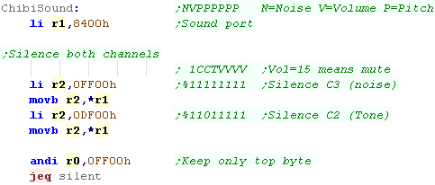
Here's ChibiSound!
| The sound port is 8400h... we load this into R1 - this means we
can send sound data to reg *r1 First we silence the sound chip - we need to do this by setting the volume to 15 (higher is quieter)... we define a volume setting with bit 4- the volume is defined by the bottom 4 bits... the channel number is bits 5 and 6 Chibisound uses two channels... channel 2 for tones and channel 3 for noise. Chibisound uses a 1 byte parameter in R0 - if it's zero, then we're done, as we're not playing any sound |
 |
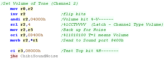
| We're going to set the volume of Channel 2 - to do this Bit 7
and Bit 4 need to be 1. What happens next depends on if we want to make a tone or a noise |
 |
| If we're making a tone we'll set up the tone channel pitch... to
define the tone we first write a byte with bit 7 as 1, and bit 4
as 0... the bottom 4 bits are the low bits of the tone... we're
defining channel 2 Next we send the second byte - with bit 7 as 0 - bits 0-5 are the high bits of the tone. |
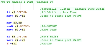 |
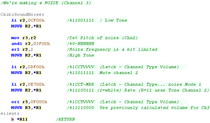
| If we're making a noise then we need to do two things. We need
to set up channel 3 for noise - but channel 3 will be linked to
channel 2 There fore we still need to set the tone of Channel 2 (though we'll mute it) We then set up the noise - we set the noise type to 1 which means White Noise... we set the rate to 3 which means the rate is taken from channel 2 finally we silence channel 2 and set the volume for channel 3 |
 |
| If we're feeling
clever, we can use the TI99 sound chip to play digital samples...
this was previously covered in the z80 series on the SMS
(basically the same chip)... take a look here |
|
| View Options |
| Default Dark |
| Simple (Hide this menu) |
| Print Mode (white background) |
| Top Menu |
| ***Main Menu*** |
| Youtube channel |
| Patreon |
| Introduction to Assembly (Basics for absolute beginners) |
| Amazon Affiliate Link |
| AkuSprite Editor |
| ChibiTracker |
| Dec/Bin/Hex/Oct/Ascii Table |
| Alt Tech |
| Archive.org |
| Bitchute |
| Odysee |
| Rumble |
| DailyMotion |
| Please note: I wlll upload more content to these alt platforms based on the views they bring in |
| 68000 Content |
| ***68000 Tutorial List*** |
Learn 68000 Assembly  |
| Hello World Series |
| Platform Specific Series |
| Simple Samples |
| Grime 68000 |
| 68000 Downloads |
| 68000 Cheatsheet |
| Sources.7z |
| DevTools kit |
| 68000 Platforms |
| Amiga 500 |
| Atari ST |
| Neo Geo |
| Sega Genesis / Mega Drive |
| Sinclair QL |
| X68000 (Sharp x68k) |
| 8086 Content |
| Learn 8086 Assembly |
| Platform Specific Series |
| Hello World Series |
| Simple Samples |
| 8086 Downloads |
| 8086 Cheatsheet |
| Sources.7z |
| DevTools kit |
| 8086 Platforms |
| Wonderswan |
| MsDos |
| ARM Content |
| Learn ARM Assembly |
| Learn ARM Thumb Assembly |
| Platform Specific Series |
| Hello World |
| Simple Samples |
| ARM Downloads |
| ARM Cheatsheet |
| Sources.7z |
| DevTools kit |
| ARM Platforms |
| Gameboy Advance |
| Nintendo DS |
| Risc Os |
| Risc-V Content |
| Learn Risc-V Assembly |
| Risc-V Downloads |
| Risc-V Cheatsheet |
| Sources.7z |
| DevTools kit |
| MIPS Content |
| Learn Risc-V Assembly |
| Platform Specific Series |
| Hello World |
| Simple Samples |
| MIPS Downloads |
| MIPS Cheatsheet |
| Sources.7z |
| DevTools kit |
| MIPS Platforms |
| Playstation |
| N64 |
| PDP-11 Content |
| Learn PDP-11 Assembly |
| Platform Specific Series |
| Simple Samples |
| PDP-11 Downloads |
| PDP-11 Cheatsheet |
| Sources.7z |
| DevTools kit |
| PDP-11 Platforms |
| PDP-11 |
| UKNC |
| TMS9900 Content |
| Learn TMS9900 Assembly |
| Platform Specific Series |
| Hello World |
| TMS9900 Downloads |
| TMS9900 Cheatsheet |
| Sources.7z |
| DevTools kit |
| TMS9900 Platforms |
| Ti 99 |
| 6809 Content |
| Learn 6809 Assembly |
| Learn 6309 Assembly |
| Platform Specific Series |
| Hello World Series |
| Simple Samples |
| 6809 Downloads |
| 6809/6309 Cheatsheet |
| Sources.7z |
| DevTools kit |
| 6809 Platforms |
| Dragon 32/Tandy Coco |
| Fujitsu FM7 |
| TRS-80 Coco 3 |
| Vectrex |
| 65816 Content |
| Learn 65816 Assembly |
| Hello World |
| Simple Samples |
| 65816 Downloads |
| 65816 Cheatsheet |
| Sources.7z |
| DevTools kit |
| 65816 Platforms |
| SNES |
| eZ80 Content |
| Learn eZ80 Assembly |
| Platform Specific Series |
| eZ80 Downloads |
| eZ80 Cheatsheet |
| Sources.7z |
| DevTools kit |
| eZ80 Platforms |
| Ti84 PCE |
| IBM370 Content |
| Learn IBM370 Assembly |
| Simple Samples |
| IBM370 Downloads |
| IBM370 Cheatsheet |
| Sources.7z |
| DevTools kit |
| Super-H Content |
| Learn SH2 Assembly |
| Hello World Series |
| Simple Samples |
| SH2 Downloads |
| SH2 Cheatsheet |
| Sources.7z |
| DevTools kit |
| SH2 Platforms |
| 32x |
| Saturn |
| PowerPC Content |
| Learn PowerPC Assembly |
| Hello World Series |
| Simple Samples |
| PowerPC Downloads |
| PowerPC Cheatsheet |
| Sources.7z |
| DevTools kit |
| PowerPC Platforms |
| Gamecube |
| Work in Progress |
| ChibiAndroids |
| Misc bits |
| Ruby programming |
Buy my Assembly programming book
on Amazon in Print or Kindle!


Available worldwide!
Search 'ChibiAkumas' on
your local Amazon website!
Click here for more info!


Buy my Assembly programming book
on Amazon in Print or Kindle!
Available worldwide!
Search 'ChibiAkumas' on
your local Amazon website!
Click here for more info!
Buy my Assembly programming book
on Amazon in Print or Kindle!
Available worldwide!
Search 'ChibiAkumas' on
your local Amazon website!
Click here for more info!