

65c02 Assembly programming for the Atari Lynx
| The Atari Lynx uses the 65c02...
coupled with a 16 bit GPU, the Atari Lynx is was far more powerful
than the Gameboy and Sega Master system Although it's large size, and high power draw made it a commercial failure, it's an interesting system to develop for! The official cartridges are encrypted, but we can make a binary that the emulator Handy can run quite easily! Unlike most other systems, the Lynx does not have a tile array, a chunk of about 8k of internal memory is used for the screen, and we can write bytes directly to it (like on the CPC)... the hardware sprite function also writes to this buffer, so we have no effective sprite limit! |
 |
 |
 |
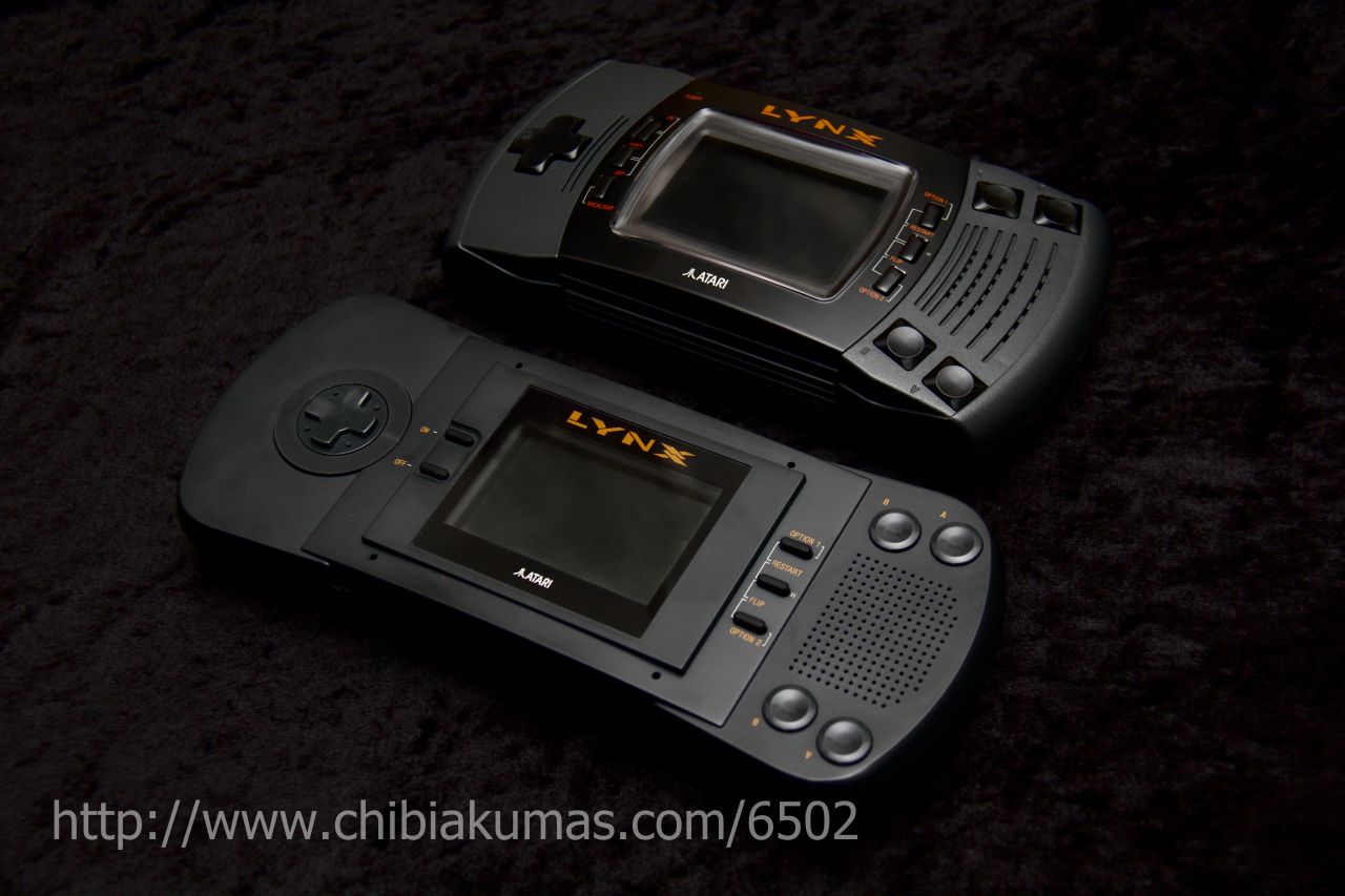
There were two models of the atari
Lynx, but there's no real difference between them.
|
 |
ChibiAkumas Tutorials
| |
Lesson P4 - Bitmap Functions on the Atari Lynx |
| Lesson P13 - Joystick Reading on the Atari Lynx | |
| Lesson P19 - Palette definitions on the Atari Lynx | |
| Lesson P24 - Sound on the Atari Lynx | |
Memory Map
| From
|
To
|
Use |
| $0000 | $00FF | Zero Page |
| $0100 | $01FF | Stack |
| $0200 | $FBFF | Program RAM |
| $FC00 | $FCFF | Suzy |
| $DF00 | $FDFF | Mikey |
| $FE00 | $FFF7 | ROM |
| $FFFA | $FFFB | NMI Address |
| $FFFC | $FFFD | Reset Address |
| $FFFE | $FFFF | IRQ Address |
| While real cartridges are encrypted (causing copyright problems
for the hobbyist), the Handy emulator can work with an unencrypted O
file... this also means we do not need an official rom to run the
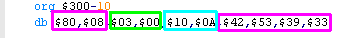
emulator! There is a 10 byte header... FixedBytes:Many of the bytes are fixed, and should not be changed StartPoint: Bytes 2 and 3 are the startpoint in Big Endian format.. . in our example the first program byte is $0300 Length: Bytes 4 and 5 are the length of the file. |
 |
Hardware Sprites
Unlike other systems, Lynx hardware sprites are not an extra layer! the 'Suzy' graphics chip draws the sprite into the Vram area of the 6502's addressable range
This may leave you wondering why not just do our sprites in software with the 6502... but the Suzy chip is VERY fast... it's a 16mhz 16 bit chip... and can even do dynamic scaling of sprites!
Sprites for the Suzy chip have to be held in RAM, and need a 'Sprite control block' to define the drawing of a sprite... this pointer is passed to the Suzy chip to get it to draw a sprite
| Sprites can be 'Literal' (plain bmp) or 'RLE compressed' (defined
by bit 7 of byte two of the SCB - SCBCTL1).... the colordepth is
defined in SPRCTL0 (See later) Each line of a sprite starts with a byte - this an offset to the next line... effectively the number of bytes in the line +1 .... effectively the pointer to the next line. 1 or 0 in this position have special meanings!... 0 means the end of the sprite... 1 means the end of the 'quardrent'... note this is optional! Akusprite does not use it! Quadrent rendering is where the sprite is drawn in 4 sections from the middle... with a 1 byte marking each 1/4 of the sprite... (followed by another 'offset to next line' byte) the first quadrent is DownRight (default)... the second quadrent is UpRight the third quadrent is UpLeft)... the fourth quadrent is DownLeft Apparently there is a bug in the hardware - the last bit of each line must be 0! - we should always have a 0 at the end of our sprites to counter it - color 0 is transparent anyway! You can see a Literal Sprite to the right... the Literal bitmap data is in green, and the header bytes are in cyan |
Literal
Sprite Example (BMP) LynxSprite: db $8, $11, $11, $11, $11, $11, $10,0 db $8, $10, $0, $0, $0, $0, $10,0 db $8, $10, $04, $44, $44, $0, $10,0 db $8, $10, $04, $3, $04, $0, $10,0 db $8, $10, $04, $3, $04, $0, $10,0 db $8, $10, $04, $44, $44, $0, $10,0 db $8, $10, $0, $0, $0, $0, $10,0 db $8, $11, $11, $11, $11, $11, $10,0 db 0 |
| RLE Sprite
Data is a bit more tricky.... The first byte in a line is again an offset to the next line as before The next BIT will be a 'block definition'... defining what the following data is... 1 marks that the next data will be LITERAL 0 marks that the next data will be RLE The next 4 bits will be the number of pixels to draw-1... so 0 means 1 pixel, and 15 means 16 pixels... we will call this N If the block is RLE the next 1/2/3/4 bits (depending on bitdepth) will be used for the color to fill the next N pixels If the block LITERAL the next N *(1/2/3/4) bits (depending on bitdepth) will be used for the color of the next N pixels the next bit will be the next 'block definition'... this pattern repeats until the line is done. |
4bpp
RLE Sprite Example db $8 (offset to next line) db %01111000,%00000000 (RLE block...16 pixels... Color 0,0,0,0,0,0,0,0,0,0,0,0,0,0,0,0) db %00001001,%10000000 (RLE block...2 pixles... Color 3,3) db %10010000,%10010001,%10000000 (Literal block...3 pixels... Color 1,2,3) (next line starts here) |
The Sprite Control Block
| The sprite control block defines the
sprite onscreen, The first two bytes define the sprite type, how
it's drawn, and the other data in the block... note if RR<2
we don't need the Scale or Tilt words... so these can be
removed. SPRCTL0 bits 7,6 defines the Colordepth 1/2/3/4 bits per pixel for 2/4/8/16 colors SPRCTL1 bit 7 defines the sprite type 1=Literal... 0=RLE Note... if you have the BPP wrong on a RLE sprite it will be a total mess... a Literal sprite would just be stretched and a bit weird! (colors would be sort of 'dithered') The Xpos and Ypos are relative to the defined screen boundaries... Wid and Hei are scales $100=100% $200=200% The 'Palette' maps each 'color' in the sprite to a palette setting... this is most useful for 1/2bpp sprites - where we will need to select the colors each combination of bits will use. the example shown is a 4bpp 16 color sprite |
SCB: ;BBHV-TTT - SPRCTL0... B=bits per pixel H=hflip V=vflip T=type (7=normal) db %11000101 ;LSRRPSUl - SPRCTL1... L=Literal S=Sizing choice (0 only!) RR=Reloadable depth (1=Use Size 3=Use Size,ScaleTilt) db %10010000 ;P=Palette reload (0=yes) s=skipsprite u=draw up l=draw left db 0 ;- SPRCOL - 0= OFF dw 0 ;Next SCB (0=none) dw LynxSprite ;Sprite pointer dw 10 ;Xpos dw 10 ;Yos dw $200 ;Wid ($100 = 100%) dw $200 ;Hei ($100 = 100%) ; dw 0 ;Scale - not needed if B4,B5 of SPRCTL<3 ; dw 0 ;Tilt - not needed if B4,B5 of SPRCTL<2 ;Palette - maps nibbles to colors (useful for <4 bpp) db $01,$23,$45,$67,$89,$AB,$CD,$EF |
Sprite Drawing
| Lets Draw a sprite... if our visible
screen is at &C000 - the following will work! Note when setting 16-bit Suzy values, we must set the LSB before the MSB... A write to the LSB will ZERO the MSB automatically... so if we set FC09 first in this example it WILL NOT WORK! |
lda #$0
;MUST SET LSB FIRST! ;WRITE TO LSB will ZERO MSB sta $FC08 ;For sprites lda #$C0 ;Set screen ram pointer to $C000 sta $FC09 ;For sprites lda #<(SCB) sta $fc10 ldy #>(SCB) sty $fc11 lda #$5 ; 1 SprStart + 4 Everon sta $FC91 ;SPRGO sta $FD90 ;SDONEACK WaitSuzy: stz $FD91 ;CPUSLEEP lda $fc92 ;DISPCTL lsr bcs WaitSuzy stz $FD90 ;SDONEACK |
| If we want our sprites to clip at the top left, we can set a
screen offset - for example to set an offset of 8: |
LDA #8 STA $FC04 ;SCR OFFSET STA $FC06 ;SCR OFFSET |
Hardware Ports Memory Map
The Lynx memory map is pretty simple, the Zeropage is at $00xx , the Stack is at $01xx....
addresses from $0200-$FC00 are free for ram... we need to allocate $2000 for a screen buffer, which can be anywhere in ram we want (defined in address $FD94-$FD95), but the rest is ours to use!
Note: Cartridge Rom is not memory mapped, it acts more like a 'disk drive' which we have to access like an external system... which is annoying!
We need to use the hardware registers to control, and read from the devices attached to the system, they are listed below:
| From | To | Name | Description | Bits | Meaning |
| FC00 | FC01 | TMPADRL | Temporary Address LH | ||
| FC02 | FC03 | TILTACUM | Accumulator for tilt value LH | ||
| FC04 | FC05 | HOFF | Offert to H edge of screen | ||
| FC06 | FC07 | VOFF | Offert to V edge of screen | ||
| FC08 | FC09 | VIDBAS | Base address of video build buffer | ||
| FC0A | FC0B | COLLBAS | Base address of Coll build buffer | ||
| FC0C | FC0D | VIDADRL | Current Video Build Addres | ||
| FC0E | FC0F | COLLARL | Current Collision Build Address | ||
| FC10 | FC11 | SCBNEXT | Address of next SCB | ||
| FC12 | FC13 | SPRDLINE | Start of Sprite Data Line Address | ||
| FC14 | FC15 | HPOSSTRT | Starting Hpos | ||
| FC16 | FC17 | VPOSSTRT | Starting Vpos | ||
| FC18 | FC19 | SPRHSIZ | Hsize | ||
| FC1A | FC1B | SPRVSIZ | Vsize | ||
| FC1C | FC1D | STRETCH | H Size Adder | ||
| FC1E | FC1F | TILT | H Position Adder | ||
| FC20 | FC21 | SPRDOFF | Offset to next sprite data line | ||
| FC22 | FC23 | SPRVPOS | Current Vpos | ||
| FC24 | FC25 | COLLOFF | Offset to collision depository | ||
| FC26 | FC27 | VSIZACUM | Vertical Size Accumulator | ||
| FC28 | FC29 | HSIZOFF | Horizontal size offset | ||
| FC2A | FC2B | VSIZOFF | Vertical Size Offeet | ||
| FC2C | FC2D | SCBADR | Address of current SCB | ||
| FC2E | FC2F | PROCADR | Current Spr data Proc Address | |
|
| FC80 | FC80 | SPRCTRL0 | BBHV-TTT | B=bits per
pixel H=hflip V=vflip T=type (7=normal) |
|
| FC81 | FC81 | SPRCTRL1 | LSRRPSUl | L=Literal S=Sizing choice (0 only!) RR=Reloadable depth P=Palette reload (0=yes) s=skipsprite u=draw up l=draw left |
|
| FC82 | FC82 | SPRCOLL | |||
| FC83 | FC83 | SPRINT | |||
| FC88 | FC88 | SUZYHrev | Suzy Hardware Revision R | ||
| FC89 | FC89 | SUZYHrev | Suzy Hardware Revision W | ||
| FC90 | FC90 | SUZYBUSEN | Suzy bus enable FF | ||
| FC91 | FC91 | SPRGO | Sprite Process start bit | ---E-S | S=Sprites on E=Everon detector(?) |
| FC92 | FC92 | SPRSYS | System Cotrlol Bits (RW) | ||
| FCB0 | FCB0 | JOYSTICK | Read Joystick and Switches | UDLR12IO | |
| FCB1 | FCB1 | SWITCHES | Read other switches | -----CCP | |
| FCB2 | FCB3 | RCART | Rcart (RW) | ||
| FCC0 | FCC0 | LEDS | Leds (W) | ||
| FCC2 | FCC2 | PPT | Paralell port Status RW | ||
| FCC3 | FCC3 | PPT DATA | Paralell port Data RW | ||
| FCC4 | FCC4 | Howie | Howie (RW) | ||
| FD00 | TIM0BKUP | HTIMBKUP Timer 0 backup value (Hblank) | Count +1 | ||
| FD01 | TIM0CTLA | HTIMCTL0 Timer 0 static control (Hblank) | ID-RCSSS | I=enable Interrupt, D=Reset Timer Done R=enable Reload C enable Count S=Clock Select | |
| FD02 | TIM0CNT | Timer 0 current count (Hblank) | Timer Current Value | ||
| FD03 | TIM0CTLB | Timer 0 dynamic control (Hblank) | ---DLIO | D=timer Done L=Last clock I=borrow In O=borrow Out | |
| FD04 | TIM1BKUP | MAGA Timer 1 backup vatue | Count +1 | ||
| FD05 | TIM1CTLA | Timer 1 static control | IDMRCSSS | I=enable Interrupt, D=Reset Timer Done M=Magmode (1,3,5,7 only) R=enable Reload C enable Count S=Clock Select | |
| FD06 | TIM1CNT | Timer 1 current count | Timer Current Value | ||
| FD07 | TlM1CTLB | Timer 1 dynamic control | ---DLIO | D=timer Done L=Last clock I=borrow In O=borrow Out | |
| FD08 | TlM2BKUP | VTIMBKUP Timer 2 backup value (Vblank) | Count +1 | ||
| FD09 | TIM2CTLA | Timer 2 static control (Vblank) | ID-RCSSS | I=enable Interrupt, D=Reset Timer Done R=enable Reload C enable Count S=Clock Select | |
| FD0A | TIM2CNT | Timer 2 current count (Vblank) | Timer Current Value | ||
| FD0B | TIM2CTLB | Timer 2 dynamic control (Vblank) | ---DLIO | D=timer Done L=Last clock I=borrow In O=borrow Out | |
| FD0C | TIM3BKUP | MAGB Timer 3 backup value | Count +1 | ||
| FD0D | TIM3CTLA | Timer 3 static control | IDMRCSSS | I=enable Interrupt, D=Reset Timer Done M=Magmode (1,3,5,7 only) R=enable Reload C enable Count S=Clock Select | |
| FD0E | TIM3CNT | Timer 3 current count | Timer Current Value | ||
| FD0F | TIM3CTLB | Timer 3 dynamic control | ---DLIO | D=timer Done L=Last clock I=borrow In O=borrow Out | |
| FD10 | TIM4BKUP | BAUDBKUP Timer 4 backup value | Count +1 | ||
| FD11 | TIM4CTLA | Timer 4 static control | ID-RCSSS | I=enable Interrupt, D=Reset Timer Done R=enable Reload C enable Count S=Clock Select | |
| FD12 | TIM4CNT | Timer 4 current count | Timer Current Value | ||
| FD13 | TlM4CTLB | Timer 4 dynamic control | ---DLIO | D=timer Done L=Last clock I=borrow In O=borrow Out | |
| FD14 | TIM5BKUP | MAGC Timer 5 backup value | Count +1 | ||
| FD15 | TIMSCTLA | Timer 5 static control | IDMRCSSS | I=enable Interrupt, D=Reset Timer Done M=Magmode (1,3,5,7 only) R=enable Reload C enable Count S=Clock Select | |
| FD16 | TIM5CNT | Timer 5 current count | Timer Current Value | ||
| FD17 | TIMSCTLB | Timer 5 dynamic control | ---DLIO | D=timer Done L=Last clock I=borrow In O=borrow Out | |
| FD18 | TIM6BKUP | Timer 6 backup value | Count +1 | ||
| FD19 | TIM6CTLA | Timer 6 static control | ID-RCSSS | I=enable Interrupt, D=Reset Timer Done R=enable Reload C enable Count S=Clock Select | |
| FD1A | TIM6CNT | Timer 6 current count | Timer Current Value | ||
| FD1B | TIM6CTLB | Timer 6 dynamic control | ---DLIO | D=timer Done L=Last clock I=borrow In O=borrow Out | |
| FD1C | TIM7BKUP | MAGD Timer 7 backup value | Count +1 | ||
| FD1D | TIM7CTLA | Timer 7 static control | IDMRCSSS | I=enable Interrupt, D=Reset Timer Done M=Magmode (1,3,5,7 only) R=enable Reload C enable Count S=Clock Select | |
| FD1E | TIM7CNT | Timer 7 current count | Timer Current Value | ||
| FD1F | TIM7CTLB | Timer 7 dynamic control | ---DLIO | D=timer Done L=Last clock I=borrow In O=borrow Out | |
| FD20 | FD20 | Audio Channel 0 � 2�s compliment Volume control | 0-127 |
||
| FD21 | FD21 | Audio Channel 0 � Shift register feedback enable | eg %00010000 |
||
| FD22 | FD22 | Audio Channel 0 � Audio Output Value (Raw Data) | Eg $80 |
||
| FD23 | FD23 | Audio Channel 0 �Lower 8 bits of shift register | Eg 0 |
||
| FD24 | FD24 | Audio Channel 0 � Audio Timer Backup Value | eg 0-63 |
||
| FD25 | FD25 | Audio Channel
0 � Audio Control Bits |
FTIRCKKK | eg %00011110 |
|
| FD26 | FD26 | Audio Channel 0 � Audio Counter | |||
| FD27 | FD27 | Audio Channel 0 �Other Audio Bits | Eg 0 | ||
| FD28 | FD2F | Audio Channel 1 � Same as Channel 0 |
|||
| FD30 | FD37 | Audio Channel 2 � Same as Channel 0 | |||
| FD38 | FD3F | Audio Channel 3 � Same as Channel 0 | |||
| FD40 | FD40 | ATTENREG0 | LLLLRRRR � Audio Attenuation | ||
| FD41 | FD41 | ATTENREG1 | LLLLRRRR � Audio Attenuation | ||
| FD42 | FD42 | ATTENREG2 | LLLLRRRR � Audio Attenuation | ||
| FD43 | FD43 | ATTENREG3 | LLLLRRRR � Audio Attenuation | ||
| FD44 | FD44 | MPAN | Stereo attenuation selection | ||
| FD50 | FD50 | MSTEREO | Stereo disable | LLLLRRRR | 0=all on 255=all off |
| FD80 | FD80 | INTRST | Interrupt poll 0 | ||
| FD81 | FD81 | INTSET | Interrupt poll 1 | ||
| FD84 | FD84 | MAGRDY0 | Mag tape Ready Channel 0 | ||
| FD85 | FD85 | MAGRDY1 | Mag tape Ready Channel 1 | ||
| FD86 | FD86 | AUDI | Audio In | ||
| FD87 | FD87 | SYSCTRL1 | |||
| FD88 | FD88 | MIKEYHREV | Mikey Hardware Revision R | ||
| FD89 | FD89 | MikeySREV | Mikey Software Revision W | ||
| FD8A | FD8A | IODIR | Mikey Paralell IO Data direction | ||
| FD8B | FD8B | IODAT | Mikey Paralell data | ||
| FD8C | FD8C | SERCTL | Serial Control Register | ||
| FD8D | FD8D | SERDAT | Serial Data | ||
| FD90 | FD90 | SDONEACK | Suzy Done Acknowledge | ||
| FD91 | FD91 | CPUSLEEP | Cpu Bus Request Disable | ||
| FD92 | FD92 | DISPCTL | Video Bus Request Enable | ||
| FD93 | FD93 | PBKUP | Magic P count | ||
| FD94 | FD95 | DISPADR | Display Address LH | LLLLLLLL HHHHHHHH | Address of video screen |
| FD9C | FD9C | MTEST0 | |||
| FD9D | FD9D | MTEST1 | |||
| FD9E | FD9E | MTEST2 | |||
| FDA0 | FDAF | Green � Colors (0-15) | 0000GGGG | ||
| FDB0 | FDBF | Blue/Red � Colors (0-15) | BBBBRRRR | ||
| FE00 | FFF7 | ROM | |||
| FFF9 | Memory Map Control | C---VRMS | C=CPU
Cycles Ram enable: S=Suzy Ram $FC00-$FCFF / M=Mikey $FD00-$FDFF / R=Rom $FE00-$FFF7 V=Vectors ($FFFA-$FFFF) |
||
| FFFA | FFFB | CPU NMI Vector | LLLLLLLL HHHHHHHH | ||
| FFFC | FFFD | CPU Reset Vector | LLLLLLLL HHHHHHHH | ||
| FFFE | FFFF | CPU Interrupt Vector | LLLLLLLL HHHHHHHH |
| View Options |
| Default Dark |
| Simple (Hide this menu) |
| Print Mode (white background) |
| Top Menu |
| ***Main Menu*** |
| Youtube channel |
| Patreon |
| Introduction to Assembly (Basics for absolute beginners) |
| Amazon Affiliate Link |
| AkuSprite Editor |
| ChibiTracker |
| Dec/Bin/Hex/Oct/Ascii Table |
| Alt Tech |
| Archive.org |
| Bitchute |
| Odysee |
| Rumble |
| DailyMotion |
| Please note: I wlll upload more content to these alt platforms based on the views they bring in |
| 68000 Content |
| ***68000 Tutorial List*** |
Learn 68000 Assembly  |
| Hello World Series |
| Platform Specific Series |
| Simple Samples |
| Grime 68000 |
| 68000 Downloads |
| 68000 Cheatsheet |
| Sources.7z |
| DevTools kit |
| 68000 Platforms |
| Amiga 500 |
| Atari ST |
| Neo Geo |
| Sega Genesis / Mega Drive |
| Sinclair QL |
| X68000 (Sharp x68k) |
| 8086 Content |
| Learn 8086 Assembly |
| Platform Specific Series |
| Hello World Series |
| Simple Samples |
| 8086 Downloads |
| 8086 Cheatsheet |
| Sources.7z |
| DevTools kit |
| 8086 Platforms |
| Wonderswan |
| MsDos |
| ARM Content |
| Learn ARM Assembly |
| Learn ARM Thumb Assembly |
| Platform Specific Series |
| Hello World |
| Simple Samples |
| ARM Downloads |
| ARM Cheatsheet |
| Sources.7z |
| DevTools kit |
| ARM Platforms |
| Gameboy Advance |
| Nintendo DS |
| Risc Os |
| Risc-V Content |
| Learn Risc-V Assembly |
| Risc-V Downloads |
| Risc-V Cheatsheet |
| Sources.7z |
| DevTools kit |
| MIPS Content |
| Learn Risc-V Assembly |
| Platform Specific Series |
| Hello World |
| Simple Samples |
| MIPS Downloads |
| MIPS Cheatsheet |
| Sources.7z |
| DevTools kit |
| MIPS Platforms |
| Playstation |
| N64 |
| PDP-11 Content |
| Learn PDP-11 Assembly |
| Platform Specific Series |
| Simple Samples |
| PDP-11 Downloads |
| PDP-11 Cheatsheet |
| Sources.7z |
| DevTools kit |
| PDP-11 Platforms |
| PDP-11 |
| UKNC |
| TMS9900 Content |
| Learn TMS9900 Assembly |
| Platform Specific Series |
| Hello World |
| TMS9900 Downloads |
| TMS9900 Cheatsheet |
| Sources.7z |
| DevTools kit |
| TMS9900 Platforms |
| Ti 99 |
| 6809 Content |
| Learn 6809 Assembly |
| Learn 6309 Assembly |
| Platform Specific Series |
| Hello World Series |
| Simple Samples |
| 6809 Downloads |
| 6809/6309 Cheatsheet |
| Sources.7z |
| DevTools kit |
| 6809 Platforms |
| Dragon 32/Tandy Coco |
| Fujitsu FM7 |
| TRS-80 Coco 3 |
| Vectrex |
| 65816 Content |
| Learn 65816 Assembly |
| Hello World |
| Simple Samples |
| 65816 Downloads |
| 65816 Cheatsheet |
| Sources.7z |
| DevTools kit |
| 65816 Platforms |
| SNES |
| eZ80 Content |
| Learn eZ80 Assembly |
| Platform Specific Series |
| eZ80 Downloads |
| eZ80 Cheatsheet |
| Sources.7z |
| DevTools kit |
| eZ80 Platforms |
| Ti84 PCE |
| IBM370 Content |
| Learn IBM370 Assembly |
| Simple Samples |
| IBM370 Downloads |
| IBM370 Cheatsheet |
| Sources.7z |
| DevTools kit |
| Super-H Content |
| Learn SH2 Assembly |
| Hello World Series |
| Simple Samples |
| SH2 Downloads |
| SH2 Cheatsheet |
| Sources.7z |
| DevTools kit |
| SH2 Platforms |
| 32x |
| Saturn |
| PowerPC Content |
| Learn PowerPC Assembly |
| Hello World Series |
| Simple Samples |
| PowerPC Downloads |
| PowerPC Cheatsheet |
| Sources.7z |
| DevTools kit |
| PowerPC Platforms |
| Gamecube |
| Work in Progress |
| ChibiAndroids |
| Misc bits |
| Ruby programming |
Buy my Assembly programming book
on Amazon in Print or Kindle!


Available worldwide!
Search 'ChibiAkumas' on
your local Amazon website!
Click here for more info!


Buy my Assembly programming book
on Amazon in Print or Kindle!
Available worldwide!
Search 'ChibiAkumas' on
your local Amazon website!
Click here for more info!
Buy my Assembly programming book
on Amazon in Print or Kindle!
Available worldwide!
Search 'ChibiAkumas' on
your local Amazon website!
Click here for more info!