

6809 Assembly programming for the Dragon 32/64 and Tandy COCO
| The Dragon is an odd beast! Using the
impressive 6809 CPU, it somehow ends up being no better than it's
6502 competitors... part of the reason for this is it's clocked at
less than 1mhz, and part is the limited RAM and Graphics of the
system. The Dragon 32/64 are virtually the same machine, and strangely, the Tandy COCO (TRS-80 COLOR) is also 99% compatible, for this reason we'll be covering them both here. For simplicity, In these tutorials, we'll be looking at 32k systems, we won't cover the 4k/16k COCO |
 |
 |
|
 I am Dragon , hear me roar... Gao! |

ChibiAkumas Dragon/CoCo Tutorials
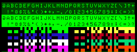
Character Map
Text characters + Semigraphics
Screen Modes
The Dragon has a variety of possible modes... the most useful being the 'Full Graphics' modes...Selecting a screen mode requires configuring two chips... the VDG via
port $FF22, and the SAM with addresses $FFC0 to $FFC5
Screenmode selection is performed by setting the top 5 bits of $FF22 and
the 3 SAM bits
Sam bits are set or cleared by writing to $FFC0-FFC5... it doesn't matter
'what' value you write... writes to Even addresses clear a bit... writes
to an odd address set a bit.
CSS bit sets the colors
| Mode Type | G/A | GM2 | GM1 | INT /GM0 | CSS | |
SAM V2 | SAM V1 | SAM V0 | Colors | Resolution | Bytes | Screen Mode |
| Internal Alphanumeric | 0 | ? | ? | 0 | ? | 0 | 0 | 0 | 2 color | 32x16 | 512 | Default (IA) |
|
| External Alphanumeric | 0 | ? | ? | 1 | ? | 0 | 0 | 0 | 4 color | 32x16 | 512 | ||
| Semigraphics 4 | 0 | ? | ? | 0 | ? | 0 | 0 | 0 | 8 color | 64 x 32 | 512 | (IA) |
|
| Semigraphics 6 | 0 | ? | ? | 1 | ? | 0 | 0 | 0 | 8 color | 64 x 48 | 512 | ||
| Semigraphics 8 | 0 | ? | ? | 0 | ? | 0 | 1 | 0 | 8 color | 64 x 64 | 2048 | ||
| Semigraphics 12 | 0 | ? | ? | 0 | ? | 1 | 0 | 0 | 8 color | 64 x 96 | 3072 | ||
| Semigraphics 24 | 0 | ? | ? | 0 | ? | 1 | 1 | 0 | 8 color | 64 x 192 | 6144 | ||
| Full Graphics 1C | 1 | 0 | 0 | 0 | ? | 0 | 0 | 1 | 4 color | 64 x 64 | 1024 | (D) | |
| Full Graphics 1R | 1 | 0 | 0 | 1 | ? | 0 | 0 | 1 | 2 color | 128 x 64 | 1024 | (E) | |
| Full Graphics 2C | 1 | 0 | 1 | 0 | ? | 0 | 1 | 0 | 4 color | 128 x 64 | 1536 | (F) | |
| Full Graphics 2R | 1 | 0 | 1 | 1 | ? | 0 | 1 | 1 | 2 color | 128 x 96 | 1536 | PMODE0 | |
| Full Graphics 3C | 1 | 1 | 0 | 0 | ? | 1 | 0 | 0 | 4 color | 128 x 96 | 3072 | PMODE1 | |
| Full Graphics 3R | 1 | 1 | 0 | 1 | ? | 1 | 0 | 1 | 2 color | 128 x 192 | 3072 | PMODE2 | |
| Full Graphics 6C | 1 | 1 | 1 | 0 | ? | 1 | 1 | 0 | 4 color | 128 x 192 | 6144 | PMODE3 | |
| Full Graphics 6R | 1 | 1 | 1 | 1 | ? | 1 | 1 | 0 | 2 color | 256 x 192 | 6144 | PMODE4 | |
| Direct Memory Access | ? | ? | ? | ? | ? | 1 | 1 | 1 | 2 color | 256 x 192 | 6144 | ||
| Port | $FF22 Bit 7 | $FF22 Bit 6 | $FF22 Bit 5 | $FF22 Bit 4 | $FF22 Bit 3 | 0:$FFC4 1:$FFC5 |
0:$FFC2 1:$FFC3 |
0:$FFC0 1:$FFC1 |
Screen Modes
Here are all the possible screen modes... 'Unofficial' modes (not
supported by basic - D/E/F) are shown with CSS=1 (alternate colors)
Text / Semigraphics (IA)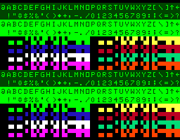 |
Full Graphics 1C (D)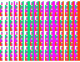 |
Full Graphics 1R (E)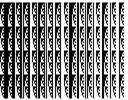 |
Full Graphics 2C (F)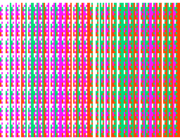 |
Full Graphics 2R (PMODE 0)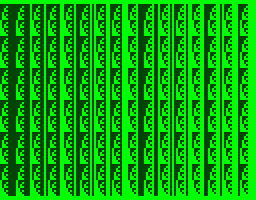 |
Full Graphics 3C (PMODE 1)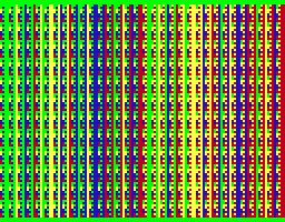 |
Full Graphics 3R (PMODE 2)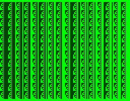 |
Full Graphics 6C (PMODE 3)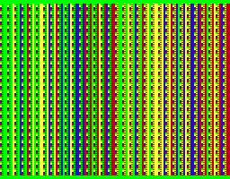 |
Full Graphics 6R (PMODE 4)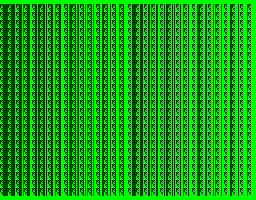 |
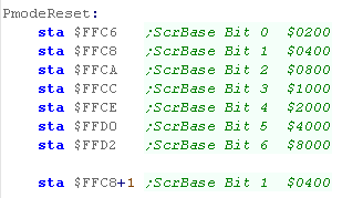
Screen Base Address
| The Top 7 bits of the Screen address can be selected by writes to
bits $FFC6-$FFD3... even addresses clear a bit, odd addresses set a
bit. Effectively the address of the screen base is:%DDDDDDD0 00000000.... where D is the bits we can change, and 0 is fixed bit zeros The example code here will reset the screen base to $0400 Writes to $FFC6-D2 set all the bits to 0... Then bit 1 is set with a write to $FFC9. |
 |
Dragon Memory Map
| Address | Dragon Purpose |
| $0000 | Direct Page |
| $0100 | System Vectors |
| $0200 | Casette Buffer |
| $0300 | Line Input Buffer |
| $0400 | Text Screen |
| $0600 | Memory Page 1 / Vars |
| $0C00 | Screen Page 2 / Program |
| $1200 | Graphics Page 3 / Basic |
| $1800 | Normal Page 4 / Extra |
| $1E00 | Memory Page 5 / Variables |
| $2400 | Screen Page 6 / Program |
| $2A00 | Graphics Page 7 / Basic |
| $3000 | Extra Page 8 / Normal |
| $3600 | Program / Var Storage & Stack (SP=$7F36) |
| $7F36 | String Space |
| $8000 | Basic Interpreter |
| $C000 | Cartridge Memory |
| $FF00 | PIA0 A Data direction Register / Peripheral Data Register |
| $FF01 | PIA0 A Control Register |
| $FF02 | PIA0 B Data direction Register / Peripheral Data Register |
| $FF03 | PIO0 B Control Register |
| $FF20 | PIA1 A Data direction Register / Peripheral Data Register |
| $FF21 | PIA1 A Control Register |
| $FF22 | PIA0 B Data direction Register / Peripheral Data Register |
| $FF23 | PIA1 B Control Register |
| $FF60 | Reserved |
| $FFC0 | Clear V0 |
| $FFC1 | Set V0 |
| $FFC2 | Clear V1 |
| $FFC3 | Set V1 |
| $FFC4 | Clear V2 |
| $FFC5 | Set V2 |
| $FFC6 | Reset Screen Addr Bit 0 |
| $FFC7 | Set Screen Addr Bit 0 |
| $FFC8 | Reset Screen Addr Bit 1 |
| $FFC9 | Set Screen Addr Bit 1 |
| $FFCA | Reset Screen Addr Bit 2 |
| $FFCB | Set Screen Addr Bit 2 |
| $FFCC | Reset Screen Addr Bit 3 |
| $FFCD | Set Screen Addr Bit 3 |
| $FFCE | Reset Screen Addr Bit 4 |
| $FFCF | Set Screen Addr Bit 4 |
| $FFD0 | Reset Screen Addr Bit 5 |
| $FFD1 | Set Screen Addr Bit 5 |
| $FFD2 | Reset Screen Addr Bit 6 |
| $FFD3 | Set Screen Addr Bit 6 |
| $FFE0 | Reserved |
| $FFF2 | SWi 3 Vector |
| $FFF4 | SWI 2 Vector |
| $FFF6 | FIRQ Vector |
| $FFF8 | IRQ Vector |
| $FFFA | SWI 1 Vector |
| $FFFC | NMI Vector |
| $FFFE | Reset Vector |
Keyboard Matrix
PAx = bits read from $FF00
PBx = Write to $FF02 with byte containing zero at this point, eg
PB0=%11111110
| PB0 (W) |
PB1 (W) | PB2 (W) | PB3 (W) | PB4 (W) | PB5 (W) | PB6 (W) | PB7 (W) | |
| PA0 (R) |
0 | 1 | 2 | 3 | 4 | 5 | 6 | 7 |
| PA1 (R) | 8 | 9 | * | , | - | � | / | |
| PA2 (R) | @ | A | B | C | D | E | F | G |
| PA3 (R) | H | I | J | K | L | M | N | 0 |
| PA4 (R) | P | Q | R | S | T | U | V | W |
| PA5 (R) | X | Y | Z | Up | Down | Left | Right | Space |
| PA6 (R) | ENT | CLR | BRK | N/C | N/C | N/C | N/C | SHFT |
| PA7 (R) | JoyTest | JoyTest | JoyTest | JoyTest | JoyTest | JoyTest | JoyTest | JoyTest |
PIA0 / PIA1 - Peripheral Interface Adapters
The PIA's select and send and receive data from the graphics chip, Keyboard, Joystick, Printer (RS232) and Sound hardware
The Data ports also double up as a 'Direction Select port' (Via bit 2 of the control port)... writing a 1 bit selects Direction IN... writing a 0 selects Direction OUT
| $FF00
|
Dir
|
PIA0-A Data |
| Bit 7 | I | Joy compare (Compare to $FF20) |
| Bit 6 | I | Key row PA6 (select with $FF02) |
| Bit 5 | I | Key row PA5 (select with $FF02) |
| Bit 4 | I | Key row PA4 (select with $FF02) |
| Bit 3 | I | Key row PA3 (select with $FF02) |
| Bit 2 | I | Key row PA2 (select with $FF02) |
| Bit 1 | I | Key row PA1 (select with $FF02) |
| Bit 0 | I | Key row PA0 (select with $FF02) |
| $FF01 | PIA0-A Control | |
| Bit 7 | IRQA1: HSYNC Flag | |
| Bit 6 | IRQA2: Unused | |
| Bit 5 | 1 -> CA2 in CRA3 in bit follow mode | |
| Bit 4 | 1 -> CA2 in CRA3 in bit follow mode | |
| Bit 3 | CA2: Select Device (Multiplexor LSB) | |
| Bit 2 | Dir/Data: 0=$FF00 Selects Direction 1=$FF00 Access Data | |
| Bit 1 | CA1 ctrl: 0=IRQ on Hi to Low... 1=IRQ on Low to Hi | |
| Bit 0 | CA1 IRQ: 0=off 1=on | |
| $FF02 | Dir | PIA0-B Data |
| Bit 7 | O | Key Col PB7 / Printer P7 |
| Bit 6 | O | Key Col PB6 / Printer P7 |
| Bit 5 | O | Key Col PB5 / Printer P7 |
| Bit 4 | O | Key Col PB4 / Printer P7 |
| Bit 3 | O | Key Col PB3 / Printer P7 |
| Bit 2 | O | Key Col PB2 / Printer P7 |
| Bit 1 | O | Key Col PB1 / Printer P7 |
| Bit 0 | O | Key Col PB0 / Printer P7 |
| $FF03 | PIA0-B Control | |
| Bit 7 | IRQB1: VSYNC Flag | |
| Bit 6 | IRQB2: Unused | |
| Bit 5 | 1 -> CB2 in CRB3 in bit follow mode | |
| Bit 4 | 1 -> CB2 in CRB3 in bit follow mode | |
| Bit 3 | CB2: Select Device (Multiplexor MSB) | |
| Bit 2 | Dir/Data: 0=$FF02 Selects Direction 1=$FF02 Access Data | |
| Bit 1 | CB1 ctrl: 0=IRQ on Hi to Low... 1=IRQ on Low to Hi | |
| Bit 0 | CB1 IRQ: 0=off 1=on | |
| $FF20 | Dir | PIA1-A Data |
| Bit 7 | O | DAC Bit 5 (Joy Compare / Sound) |
| Bit 6 | O | DAC Bit 4 (Joy Compare / Sound) |
| Bit 5 | O | DAC Bit 3 (Joy Compare / Sound) |
| Bit 4 | O | DAC Bit 2 (Joy Compare / Sound) |
| Bit 3 | O | DAC Bit 1 (Joy Compare / Sound) |
| Bit 2 | O | DAC Bit 0 (Joy Compare / Sound) |
| Bit 1 | O | RS232 Out / Printer Strobe |
| Bit 0 | I | Casette In |
| $FF21 | PIA1-A Control | |
| Bit 7 | IRQA1 Printer Ack Flag | |
| Bit 6 | IRQA2: Unused | |
| Bit 5 | CRA4 =1 -> CA2 in CRA3 bit follow mode | |
| Bit 4 | CRA4 =1 -> CA2 in CRA3 bit follow mode | |
| Bit 3 | CA2: Casette Motor (1=on) | |
| Bit 2 | Dir/Data: 0=$FF20 Selects Direction 1=$FF20 Access Data | |
| Bit 1 | CA1 ctrl: 0=IRQ on Hi to Low... 1=IRQ on Low to Hi | |
| Bit 0 | CA1 IRQ: 0=off 1=on | |
| $FF22 | Dir | PIA1-B Data |
| Bit 7 | O | ScreenMode G/A |
| Bit 6 | O | ScreenMode GM2 |
| Bit 5 | O | ScreenMode GM1 |
| Bit 4 | O | ScreenMode GM0 / INT |
| Bit 3 | O | ScreenMode CSS |
| Bit 2 | I | Ram Size (1=16k 0=32/64k)) |
| Bit 1 | I | Single bit sound |
| Bit 0 | I | Rs232 In / Printer Busy |
| $FF23 | PIA1-B Control | |
| Bit 7 | IRQB1 Cartridge Interrupt | |
| Bit 6 | IRQB2: Unused | |
| Bit 5 | CRB4 =1 -> CB2 in CRB3 bit follow mode | |
| Bit 4 | CRB4 =1 -> CB2 in CRB3 bit follow mode | |
| Bit 3 | CB2: Sound Source Enable (1=on) | |
| Bit 2 | Dir/Data: 0=$FF22 Selects Direction 1=$FF22 Access Data | |
| Bit 1 | CB1 ctrl: 0=IRQ on Hi to Low... 1=IRQ on Low to Hi | |
| Bit 0 | CB1 IRQ: 0=off 1=on |
Multiplexer Device selection
| $FF23
Bit 3 |
$FF21 Bit 3 |
$FF03 Bit 3 |
$FF01 Bit 3 | |
| PIA1-CB2 | PIA1-CA2 | PIA0-CB2 | PIA0-CA2 | |
| SoundSource
|
Cassette
Motor |
Multiplexer
H |
Multiplexer
L |
Purpose |
| 0 | ? | 0 | 0 | Write JJJJJJ-- to $FF20 .... Read ($FF00) Joystick R-X O-----LR O=1 means Over written value |
| 0 | ? | 0 | 1 | Write JJJJJJ-- to $FF20 .... Read ($FF00) Joystick R-Y O-----LR O=1 means Over written value |
| 0 | ? | 1 | 0 | Write JJJJJJ-- to $FF20 .... Read ($FF00) Joystick L-X O-----LR O=1 means Over written value |
| 0 | ? | 1 | 1 | Write JJJJJJ-- to $FF20 .... Read ($FF00) Joystick L-Y O-----LR O=1 means Over written value |
| 1 | ? | 0 | 0 | Write SSSSSS-- to $FF20 .... 6 Bit DAC |
| 1 | ? | 0 | 1 | Cassette |
| 1 | ? | 1 | 0 | Cartridge |
| 1 | ? | 1 | 1 | Unused |
Basic Commands
| Reserved word | Token | Dispatch address |
| FOR | 80 | 8448 |
| GO(TO/SUB) | 81 | 85B9 |
| REM | 82 | 8616 |
| ' | 83 | 8616 |
| ELSE | 84 | 8616 |
| IF | 85 | 8647 |
| DATA | 86 | 8613 |
| 87 | 903D | |
| ON(GOTO/SUB) | 88 | 8675 |
| INPUT | 89 | 872B |
| END | 8A | 8532 |
| NEXT | 8B | 8829 |
| DIM | 8C | 8A8B |
| READ | 8D | 8777 |
| LET | 8E | 86BC |
| RUN | 8F | 85A5 |
| RESTORE | 90 | 8514 |
| RETURN | 91 | 85F3 |
| STOP | 92 | 8539 |
| POKE | 93 | 8E9D |
| CONT | 94 | 8560 |
| LIST | 95 | 8EAA |
| CLEAR | 96 | 8571 |
| NEW | 97 | 8415 |
| DEF | 98 | 9C81 |
| CLOAD | 99 | B6D5 |
| CSAVE | 9A | B683 |
| OPEN | 9B | B829 |
| CLOSE | 9C | B64D |
| LLIST | 9D | 8EA4 |
| SET | 9E | B9D3 |
| RESET | 9F | BA04 |
| CLS | A0 | BA60 |
| MOTOR | A1 | B982 |
| SOUND | A2 | BA9B |
| AUDIO | A3 | BADF |
| EXEC | A4 | B771 |
| SKIPF | A5 | B81F |
| DELETE | A6 | 9D61 |
| EDIT | A7 | 9965 |
| TRON | A8 | 9AD9 |
| TROFF | A9 | 9ADA |
| LINE | AA | A749 |
| PCLS | AB | A8C0 |
| PSET | AC | A6EF |
| PRESET | AD | A6F3 |
| SCREEN | AE | A9FE |
| PCLEAR | AF | AA19 |
| COLOR | BO | A8D4 |
| CIRCLE | B1 | B238 |
| PAINT | B2 | AC87 |
| GET | B3 | AAF0 |
| PUT | B4 | AAF3 |
| DRAW | B5 | B051 |
| PCOPY | B6 | AABE |
| PMODE | B7 | A9AF |
| PLAY | B8 | ADBD |
| DLOAD | B9 | A049 |
| RENUM | BA | 9DFA |
Interrupt Vectors
| Address | Vector (Address) | Registers Auto-pushed onto stack |
| $FFF2 | SWi 3 Vector ($0100) | D,X,Y,U,DP,CC |
| $FFF4 | SWI 2 Vector ($0103) | D,X,Y,U,DP,CC |
| $FFF6 | FIRQ Vector ($010F) | CC |
| $FFF8 | IRQ Vector ($010C) | D,X,Y,U,DP,CC |
| $FFFA | SWI 1 Vector ($0106) | D,X,Y,U,DP,CC |
| $FFFC | NMI Vector ($0109) | D,X,Y,U,DP,CC |
| $FFFE | RESET Vector ($B3B4) | NA |
| View Options |
| Default Dark |
| Simple (Hide this menu) |
| Print Mode (white background) |
| Top Menu |
| ***Main Menu*** |
| Youtube channel |
| Patreon |
| Introduction to Assembly (Basics for absolute beginners) |
| Amazon Affiliate Link |
| AkuSprite Editor |
| ChibiTracker |
| Dec/Bin/Hex/Oct/Ascii Table |
| Alt Tech |
| Archive.org |
| Bitchute |
| Odysee |
| Rumble |
| DailyMotion |
| Please note: I wlll upload more content to these alt platforms based on the views they bring in |
| 68000 Content |
| ***68000 Tutorial List*** |
Learn 68000 Assembly  |
| Hello World Series |
| Platform Specific Series |
| Simple Samples |
| Grime 68000 |
| 68000 Downloads |
| 68000 Cheatsheet |
| Sources.7z |
| DevTools kit |
| 68000 Platforms |
| Amiga 500 |
| Atari ST |
| Neo Geo |
| Sega Genesis / Mega Drive |
| Sinclair QL |
| X68000 (Sharp x68k) |
| 8086 Content |
| Learn 8086 Assembly |
| Platform Specific Series |
| Hello World Series |
| Simple Samples |
| 8086 Downloads |
| 8086 Cheatsheet |
| Sources.7z |
| DevTools kit |
| 8086 Platforms |
| Wonderswan |
| MsDos |
| ARM Content |
| Learn ARM Assembly |
| Learn ARM Thumb Assembly |
| Platform Specific Series |
| Hello World |
| Simple Samples |
| ARM Downloads |
| ARM Cheatsheet |
| Sources.7z |
| DevTools kit |
| ARM Platforms |
| Gameboy Advance |
| Nintendo DS |
| Risc Os |
| Risc-V Content |
| Learn Risc-V Assembly |
| Risc-V Downloads |
| Risc-V Cheatsheet |
| Sources.7z |
| DevTools kit |
| MIPS Content |
| Learn Risc-V Assembly |
| Platform Specific Series |
| Hello World |
| Simple Samples |
| MIPS Downloads |
| MIPS Cheatsheet |
| Sources.7z |
| DevTools kit |
| MIPS Platforms |
| Playstation |
| N64 |
| PDP-11 Content |
| Learn PDP-11 Assembly |
| Platform Specific Series |
| Simple Samples |
| PDP-11 Downloads |
| PDP-11 Cheatsheet |
| Sources.7z |
| DevTools kit |
| PDP-11 Platforms |
| PDP-11 |
| UKNC |
| TMS9900 Content |
| Learn TMS9900 Assembly |
| Platform Specific Series |
| Hello World |
| TMS9900 Downloads |
| TMS9900 Cheatsheet |
| Sources.7z |
| DevTools kit |
| TMS9900 Platforms |
| Ti 99 |
| 6809 Content |
| Learn 6809 Assembly |
| Learn 6309 Assembly |
| Platform Specific Series |
| Hello World Series |
| Simple Samples |
| 6809 Downloads |
| 6809/6309 Cheatsheet |
| Sources.7z |
| DevTools kit |
| 6809 Platforms |
| Dragon 32/Tandy Coco |
| Fujitsu FM7 |
| TRS-80 Coco 3 |
| Vectrex |
| 65816 Content |
| Learn 65816 Assembly |
| Hello World |
| Simple Samples |
| 65816 Downloads |
| 65816 Cheatsheet |
| Sources.7z |
| DevTools kit |
| 65816 Platforms |
| SNES |
| eZ80 Content |
| Learn eZ80 Assembly |
| Platform Specific Series |
| eZ80 Downloads |
| eZ80 Cheatsheet |
| Sources.7z |
| DevTools kit |
| eZ80 Platforms |
| Ti84 PCE |
| IBM370 Content |
| Learn IBM370 Assembly |
| Simple Samples |
| IBM370 Downloads |
| IBM370 Cheatsheet |
| Sources.7z |
| DevTools kit |
| Super-H Content |
| Learn SH2 Assembly |
| Hello World Series |
| Simple Samples |
| SH2 Downloads |
| SH2 Cheatsheet |
| Sources.7z |
| DevTools kit |
| SH2 Platforms |
| 32x |
| Saturn |
| PowerPC Content |
| Learn PowerPC Assembly |
| Hello World Series |
| Simple Samples |
| PowerPC Downloads |
| PowerPC Cheatsheet |
| Sources.7z |
| DevTools kit |
| PowerPC Platforms |
| Gamecube |
| Work in Progress |
| ChibiAndroids |
| Misc bits |
| Ruby programming |
Buy my Assembly programming book
on Amazon in Print or Kindle!


Available worldwide!
Search 'ChibiAkumas' on
your local Amazon website!
Click here for more info!


Buy my Assembly programming book
on Amazon in Print or Kindle!
Available worldwide!
Search 'ChibiAkumas' on
your local Amazon website!
Click here for more info!
Buy my Assembly programming book
on Amazon in Print or Kindle!
Available worldwide!
Search 'ChibiAkumas' on
your local Amazon website!
Click here for more info!