

6809 Assembly programming for the Fujitsu FM-7
| The FM-7 is one of a series of
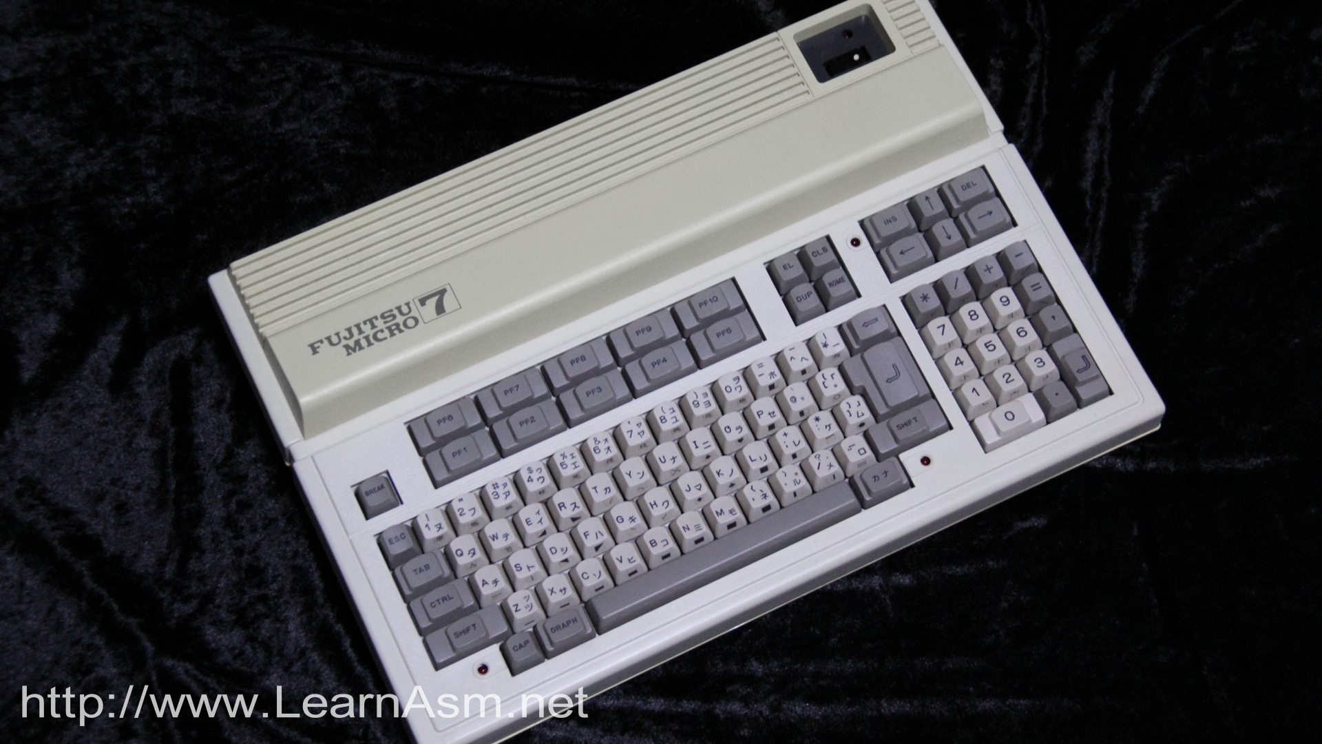
Fujitsu computers released in Japan With a pair of 6809 CPU's it was widely popular in Japan, and is one of the few 6809 computers released. In these tutorials we'll learn the about the FM7, and write some simple programs for it |
 |
 |
|
 |

ChibiAkumas FM7 Tutorials
Useful Documentation
FM7 New7 77 Assembly Introduction
Hello World Example
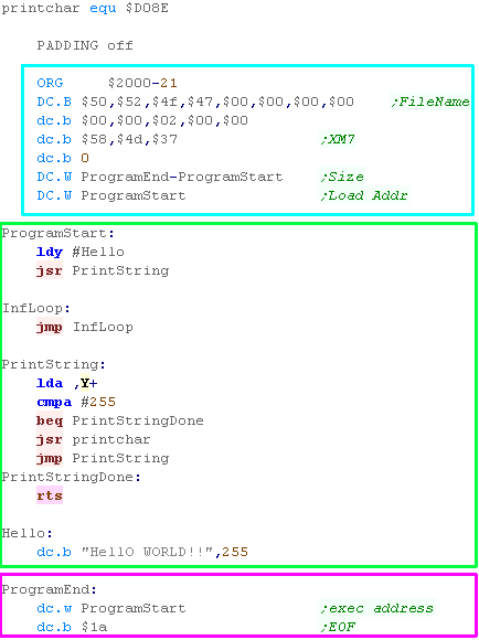
| Here is a sample file... We've provided a Header, containing the Length and destination load address... There is also an Exec address in the footer, however this does not actually have any effect! The hello world example uses the PrintChar routine in the basic rom at $D08E of the FM-7 OS |
 |
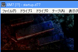
StartUp File
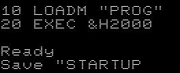
| To make our disk automatically start, we need a basic launcher. Here we've written a BAS file, it will load machine code program "PROG" (which has a built in destination address of &H2000) Next we execute it with an EXEC command We need to save this as "STARTUP" (Case Sensitive) |
 |
Building our program to the disk
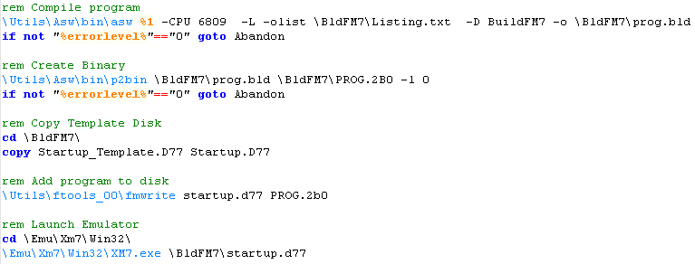
| We need to create a binary file (with a 2b0 extension) We use ASW to compile the program, and P2Bin to convert it to a binary. To add a file to a disk we'll need the Ftools kit We'll use a template disk (with our STARTUP bas) and attach the 2b0 file to it |
 |
Sending Data to the Sub CPU
| The Sub CPU handles graphics drawing and key input - it's a second
6809 To control it we have to send data to it via a 128 byte shared memory block, between $FC80-FCFF ($D380-D3FF on the Sub CPU side) To do this, we have to: 1. Wait for the Sub Cpu to not be busy (wait for Bit7 in $FD05 to equal 0) 2. Halt the Sub Cpu (set Bit 7 of $FD05 to 1) 3. Copy command data to $FC80-FCFF 4. Resume the Sub CPU (write 0 to $FD05) The command will then be processed by the sub CPU |
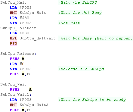 |
| if we HALT and RESUME the sub cpu but don't set a command there
WILL be trouble! When we do this we need to set the 'request ready' bit (Bit 7 of $F780) - this will stop the SUB CPU trying to process a command and getting confused. |
 |
RAM Main CPU
| From | To | Use |
| $0000 | $7FFF | Ram |
| $8000 | $FBFF | Basic Rom / Ram ** |
| $FC00 | $FC7F | Ram |
| $FC80 | $FCFF | Shared Ram (With SUB CPU $D380) |
| $FD00 | $FDFF | IO area |
| $FE00 | $FEEF | Boot Rom |
| $FFF0 | $FFFF | Vectors |
** $FD0F Enable/Disable Basic ROM 8000-FC00 (Write=Disable... Read=
Enable)
RAM Sub CPU
| From | To | Use |
| $0000 | $3FFF | VRAM (BLUE) |
| $4000 | $7FFF | VRAM (RED) |
| $8000 | $BFFF | VRAM (GREEN) |
| $C000 | $CFFF | Console Buffer Ram |
| $D000 | $D37F | Work Ram |
| $D380 | $D3FF | Shared Ram (With MAIN CPU $FC80) |
| $D400 | $D7FF | IO area |
| $D800 | $DFFF | Character Rom |
| $E000 | $FFFF | CRT Monitor Rom |
Ports on the Main CPU
| Address | Read Bits | Read Purpose | Write Bits | Write Purpose |
| $FD00 | D-------M | Key Clock D8 | Ss-------Ao | Audio Casette / Printer |
| $FD01 | DDDDDDDD | Key Data | DDDDDDDD | Printer Data |
| $FD02 | A-PPPPPP | Audio Casette / Printer | RRRR-TPK | IRQ |
| $FD03 | ----ETPK | IRQ | CK-----S | Buzzer |
| $FD04 | ------BA | SubCpu Brk / Attention | ||
| $FD05 | B------E | SubCPU Busy / Extdet | HC-----Z | Halt / Cancel / Z80 |
| $FD06 | DDDDDDDD | RS232 Data | DDDDDDDD | RS232 Data |
| $FD07 | SSSSSSSS | RS232 Status | CCCCCCCC | RS232 Comand |
| $FD0D | RRRRRRRR | PSG AY Register (need to write zero after reg num?) | ||
| $FD0E | DDDDDDDD | PSG AY Data | DDDDDDDD | PSG AY Data |
| $FD0F | BBBBBBBB | ROM Bank | BBBBBBBB | Ram Bank |
| $FD18 | SSSSSSSS | Floppy Status | CCCCCCCC | Floppy Command |
| $FD19 | DDDDDDDD | Floppy Track Register | DDDDDDDD | Floppy Track Register |
| $FD1A | DDDDDDDD | Floppy Sector Register | DDDDDDDD | Floppy Sector Register |
| $FD1B | DDDDDDDD | Floppy Sector Register | DDDDDDDD | Floppy Sector Register |
| $FD1C | DDDDDDDD | Floppy | DDDDDDDD | Floppy |
| $FD1D | DDDDDDDD | Floppy | DDDDDDDD | Floppy |
| $FD1E | DDDDDDDD | Floppy | DDDDDDDD | Floppy |
| $FD1F | DI------ | Floppy | Floppy | |
| $FD20 | Kanji Rom 1 | DDDDDDDD | Kanji Rom 1 | |
| $FD21 | Kanji Rom 1 | DDDDDDDD | Kanji Rom 1 | |
| $FD22 | DDDDDDDD | Kanji Rom 1 | Kanji Rom 1 | |
| $FD23 | DDDDDDDD | Kanji Rom 1 | Kanji Rom 1 | |
| $FD2C | Kanji Rom 2 | Kanji Rom 2 | ||
| $FD2D | Kanji Rom 2 | Kanji Rom 2 | ||
| $FD2E | Kanji Rom 2 | Kanji Rom 2 | ||
| $FD2F | Kanji Rom 2 | Kanji Rom 2 | ||
| $FD2E? | Dictionary Bank | Dictionary Bank | ||
| $FD30 | Analog Palette Number | |||
| $FD31 | Analog Palette Number | |||
| $FD32 | Analog Palette Blue Level | |||
| $FD33 | Analog Palette Red Level | |||
| $FD34 | Analog Palette Green Level | |||
| $FD35 | Speech Synthesis | Speech Synthesis | ||
| $FD37 | -GRB-GRB | Multipage (Display / Write Lock) | ||
| $FD38 | -----GRB | Palette 0 (---) | -----GRB | Palette 0 |
| $FD39 | -----GRB | Palette 1 (--B) | -----GRB | Palette 1 |
| $FD3A | -----GRB | Palette 2 (-R-) | -----GRB | Palette 2 |
| $FD3B | -----GRB | Palette 3 (-RB) | -----GRB | Palette 3 |
| $FD3C | -----GRB | Palette 4 (G--) | -----GRB | Palette 4 |
| $FD3D | -----GRB | Palette 5 (G-B) | -----GRB | Palette 5 |
| $FD3E | -----GRB | Palette 6 (GR-) | -----GRB | Palette 6 |
| $FD3F | -----GRB | Palette 7 (GRB) | -----GRB | Palette 7 |
| $FD40 | Modem Card | Modem Card | ||
| $FD41 | Modem Card | Modem Card | ||
| $FD42 | Modem Card | |||
| $FD56 | Voice Recognition Card | Voice Recognition Card | ||
| $FD57 | Voice Recognition Card | Voice Recognition Card | ||
| $FD58 | Handy Image Scanner | |||
| $FD59 | Handy Image Scanner | |||
| $FD5A | Handy Image Scanner | |||
| $FD80 | Memory Management Register | Memory Management Register | ||
| $FD81 | Memory Management Register | Memory Management Register | ||
| $FD82 | Memory Management Register | Memory Management Register | ||
| $FD83 | Memory Management Register | Memory Management Register | ||
| $FD84 | Memory Management Register | Memory Management Register | ||
| $FD85 | Memory Management Register | Memory Management Register | ||
| $FD86 | Memory Management Register | Memory Management Register | ||
| $FD87 | Memory Management Register | Memory Management Register | ||
| $FD88 | Memory Management Register | Memory Management Register | ||
| $FD89 | Memory Management Register | Memory Management Register | ||
| $FD8A | Memory Management Register | Memory Management Register | ||
| $FD8B | Memory Management Register | Memory Management Register | ||
| $FD8C | Memory Management Register | Memory Management Register | ||
| $FD8D | Memory Management Register | Memory Management Register | ||
| $FD8E | Memory Management Register | Memory Management Register | ||
| $FD8F | Memory Management Register | Memory Management Register | ||
| $FD90 | MMR Segment Register | |||
| $FD92 | Window Offset Register | |||
| $FD93 | Mode Select Register 1 | |||
| $FD94 | CPU Speed | |||
| $FD95 | Mode Select Switch 2 | Mode Select Switch 2 | ||
| $FD98 | DMAC | |||
| $FD99 | DMAC | DMAC | ||
| $FDE0 | Mouse | |||
| $FDE1 | Mouse | Mouse | ||
| $FDE2 | Mouse | Mouse | ||
| $FDE3 | Mouse | Mouse | ||
| $FDE4 | Mouse | Mouse | ||
| $FDE5 | Mouse | Mouse | ||
| $FDE6 | Mouse | Mouse | ||
| $FDE7 | Mouse | Mouse | ||
| $FDE8 | Mouse | Mouse | ||
| $FDE9 | MIDI | |||
| $FDEA | MIDI | MIDI | ||
| $FDEB | MIDI | MIDI | ||
| $FDEC | MIDI | MIDI | ||
| $FDED | MIDI | MIDI | ||
| $FDEE | MIDI | MIDI | ||
| $FDEF | MIDI |
Ports on the Sub CPU
| Address | Read Bits | Read Purpose | Write Bits | Write Purpose |
| $D400 | DDDDDDDD | Key Data | ||
| $D401 | -------D | Key Data | ||
| $D402 | Cancel IRQ ACK | |||
| $D404 | Main CPU Attention IRQ | |||
| $D408 | CRT ON | CRT OFF | ||
| $D409 | Vram Access Set | Vram Access Reset | ||
| $D40A | Ready | Busy | ||
| $D40D | Ins LED ON | Ins LED OFF | ||
| $D40E | --HHHHHH | Vram Address H | ||
| $D40F | LLLLLLLL | Vram Address L |
Colors
| 0 | 1 | 2 | 3 | 4 | 5 | 6 | 7 |
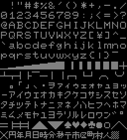
Char Map
The FM77 adds lots of new functionality, The best of which is 4096 color mode and the MMU!
| 4096 color mode allows us to use a 320x200 screen with up to 4096
colors, meaning each pixel is define by 12 bits. this means the
whole screen is a huge 96K!
The MMU is a 'Memory Mapping Unit', which allows us to map the 64k of addressable 6809 memory space to any part of the physical memory. The major benefit of this is that we can now access the VRAM without the Sub CPU! The FM77 allows for 'Page flipping' so usually two screen banks can be toggled, with one visible and the other drawn, however in 4096 color mode, these two must be used, as Page 0 contain the bit 3,2 of each color channel, and page 1 contains bit 1,0. |
 |
Writing 96k of video memory would be a real pain, but if we only want a small number of colors, we can only use a few bitplanes, and simply 'redefine' the palette, so we can use the lowest bits of Blue and Red (B1,B0,R1,R0) giving us 4 bitplanes for a palette of 16 colors out of the total 4096, or even 6 bitplanes for 64 colors, massively reducing the amount of data transferred, while giving us impressive color capabilities for an 8 bit system!
| Ram | SubCPU Ram |
Bits | |
| $010000 | $0000 | Blue
Bit B3 |
Blue
Bit B1 |
| $012000 | $2000 | Blue
Bit B2 |
Blue
Bit B0 |
| $014000 | $4000 | Red
Bit R3 |
Red
Bit R1 |
| $016000 | $6000 | Red
Bit R2 |
Red
Bit R0 |
| $018000 | $8000 | Green
Bit G3 |
Green
Bit G1 |
| $01A000 | $A000 | Green
Bit G2 |
Green
Bit G0 |
| Page/Bank 0 | Page/Bank 1 | ||
| $D430=$00 | $D430=$40 | ||
Color number bits when setting palette (0-4095):
%0 0 0 0 G3 G2 G1 G0 R3 R2 R1 R0 B3 B2 B1 B0
FM77 Memory mapper
Before using the memory mapper we need to enable it by setting bit 7 of $FD93 (Write $80)
It should be noted that while the memory can be mapped to any of the 16 4k blocks from $0000-$FFFF, the $FC00-$FFFF actually never changes, and is always mapped to the default hardware registers for the main CPU
However this gives us a great opportunity! By writing $1D to $FD8F (the MMU register for $F000-$FFFF) we can 'switch in' the hardware registers of the SUB CPU ( usually found at $D400-$D7FF on the SUB CPU) - This allows the MAIN cpu to access these registers in the range $F400-$F7FF , meaning the $F000-$FFFF range can now be used to access all hardware IO for the MAIN or SUB CPU!!!
| Port |
Bits |
Purpose |
| $FD80
|
--AAAAAA
|
MMR (Ram Bank) $0xxx range... bits 17-12 |
| $FD81 | --AAAAAA | MMR (Ram Bank) $1xxx range... bits 17-12 |
| $FD82 | --AAAAAA | MMR (Ram Bank) $2xxx range... bits 17-12 |
| $FD83 | --AAAAAA | MMR (Ram Bank) $3xxx range... bits 17-12 |
| $FD84 | --AAAAAA | MMR (Ram Bank) $4xxx range... bits 17-12 |
| $FD85 | --AAAAAA | MMR (Ram Bank) $5xxx range... bits 17-12 |
| $FD86 | --AAAAAA | MMR (Ram Bank) $6xxx range... bits 17-12 |
| $FD87 | --AAAAAA | MMR (Ram Bank) $7xxx range... bits 17-12 |
| $FD88 | --AAAAAA | MMR (Ram Bank) $8xxx range... bits 17-12 |
| $FD89 | --AAAAAA | MMR (Ram Bank) $9xxx range... bits 17-12 |
| $FD8A | --AAAAAA | MMR (Ram Bank) $Axxx range... bits 17-12 |
| $FD8B | --AAAAAA | MMR (Ram Bank) $Bxxx range... bits 17-12 |
| $FD8C | --AAAAAA | MMR (Ram Bank) $Cxxx range... bits 17-12 |
| $FD8D | --AAAAAA | MMR (Ram Bank) $Dxxx range... bits 17-12 |
| $FD8E | --AAAAAA | MMR (Ram Bank) $Exxx range... bits 17-12 |
| $FD8F | --AAAAAA | MMR (Ram Bank) $F000-$FBFF... bits 17-12 |
| $FD93 | MW-----B | Mode Select Register 1.. M=Mmu W=Window B=Boot Ram |
Special Chars
| Code | Meaning | |
| $11 | SF | Start Field |
| $12,X,Y | SBA | Set Buffer Address (Locate) |
| $13,count,Ascii | RC | Repeat Character |
| $05 | EL | Erase Line |
| $07 | BEL | BELL (Beep) |
| $08 | BS | BackSpace |
| $09 | HT | Horizontal TAB |
| $0A | LF | Line Feed |
| $0B | HOME | Buffer Address to top of screen |
| $0C | EA | Erase All (CLS) |
| $0D | CR | Carrage Return |
| $1C | Right Cursor | |
| $1D | Left Cursor | |
| $1E | Up Cursor | |
| $1F | Down Cursor | |
| $1B,$23 | Lock Keyboard | |
| $1B,$22 | Unlock Keyboard | |
| $1B,$39 | Erase Key Buffer | |
| $1B,$67 | Set Buffered Mode | |
| $1B,$69 | Set Unbuffered Mode |
Graphics Operations
| Code |
Op | Details |
| 0 | PSET | Set to Color |
| 1 | PRESET | Set to background Color |
| 2 | OR | Add to |
| 3 | AND | Mask |
| 4 | XOR | Invert |
| 5 | NOT | Flip bits |
Commands that can be sent to the Sub CPU
There are a variety of commands that can be sent to the Sub CPU, there
are some special 'secret' ones called the YAMAUCHI calls (Also know as
TEST commands),
These allow data to be direct copied to the SubCPU and allows for
execution
| Gfx Cmd |
Name |
Purpose | Data (Load into #$FC80) | Returns |
| $01 | INIT | Init Console | DC.B unused,unused DC.B $01,Background DC.B Widh,Hei (80/40,25/20) DC.B ScrollStart,ScrollEnd DC.B SHowFunctions,ClearScreen,GreenScreen |
|
| $02 | ERASE | Clear screen | DC.B unused,unused DC.B $02,Mode (0-3),Color |
|
| $03 | PUT | Print Characters |
dc.b unused,unused dc.b continue (128=yes) dc.b unused dc.b $03 dc.b Bytecount dc.b StringToSend |
|
| $04 | GET | |||
| $05 | GETC | |||
| $06 | Get Character Block 1 | |||
| $07 | Put Character Block 1 | |||
| $08 | Get Character Block 2 | |||
| $09 | Put Character Block 2 | |||
| $0A | Get Buffer Address | |||
| $0B | Tab Set | |||
| $0C | Console Control | |||
| $0D | Erase 2 | |||
| $15 | Line | Draw Lines, Fill Boxes |
dc.b unused,unused dc.b $15,color,operation dc.w StartX,StartY,EndX,EndY dc.b mode (0=line,1=square,2=filled) |
|
| $16 | Chain | Draw a series of lines |
||
| $17 | Point | Draw Dots |
dc.b unused,unused dc.b $17,points (1-20) (for each point) dc.w Xpos,Ypos ;(X,Y) dc.b Color,Operation ;Color,Operation |
|
| $18 | Paint | Fill an area |
dc.b $18 dc.w Xpos,Ypos dc.b FillColor dc.b BoundaryCount dc.b BoundaryColor....BoundaryColor |
|
| $19 | Symbol | Draw text with color, Scale and rotation |
dc.b unused,unused dc.b $19,Color,Operation dc.b Rotation (0,90,180,270) dc.b ScaleX,ScaleY (1=normal) dc.w Xpos,Ypos dc.b StringLen dc.b "String" |
|
| $1A | Change Color | Swap colors for other colors |
dc.b $1A dc.w StartX,StartY,EndX,EndY dc.b 2 ;SwapCount dc.b 7,6 ;Old Color,New Color dc.b 4,3 ;Old Color,New Color |
|
| $1B | Get Block 1 | |||
| $1C | Put Block 1 | Send Monocrome data |
||
| $1D | Get Block 2 | dc.b unused,unused dc.b $1D dc.w StartX,StartY,EndX,EndY |
DC.B ErrorCode DC.B Flag (MSB=1=Multiblock) DC.B unused DC.B bytecount (3-124) .... Pattern bytes (Each bitplane split into separate block of bytes, but bits from multiple lines in a single byte if width not divisible by 8) |
|
| $1E | Put Block 2 | Send Color Data |
dc.b unused,Multiblock (128=Y) dc.b $1E dc.w StartX,StartY,EndX,EndY dc.b Unused, Function, Bytes dc.b pixel,pixel,pixel.... |
|
| $1F | Graphics Cursor | |||
$20 |
Character Line | |||
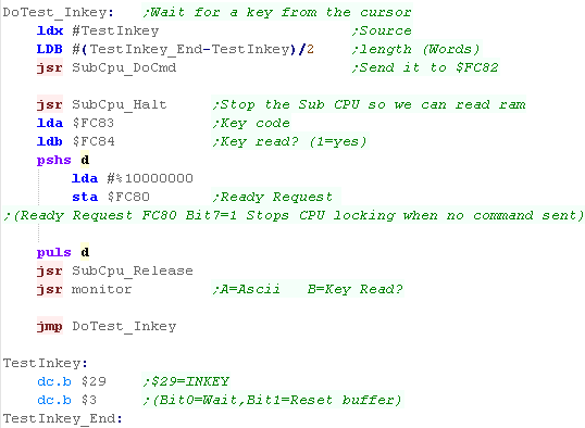
| $29 | Inkey | DC.B unused,unused DC.B $29,Option(Bit0=Wait,Bit1=Reset) |
DC.B ErrorCode,Unused,Unused DC.B,Keycode (ASCII),Keyreturned? (1=yes) |
|
| $2A | Define String of PF | |||
| $2B | Get String of PF | |||
| $2C | Interrupt Control | |||
| $3D | Set Timer | |||
| $3E | Read Timer | |||
| $3F - 90 |
YAMAUCHI END | End command sequence | DC.B unused,unused DC.B $3F,�YAMAUCHI�,$90 |
|
| $3F - 93 |
YAMAUCHI CALL | Call program in sub cpu ram | DC.B unused,unused DC.B $3F,�YAMAUCHI�,$93 DC.W {address} DC.B $90 |
|
| $3F - 92 |
YAMAUCHI MOVE | transfer data in sub cpu | DC.B unused,unused DC.B $3F,�YAMAUCHI�,$91 DC.W {FromAddrInSub} DC.W {ToAddrInSub} DC.W {LengthInBytes} DC.B $90 |
|
| $3F - 91 | YAMAUCHI JUMP | Jump to an address | DC.B unused,unused DC.B $3F,�YAMAUCHI�,$91 DC.W {address} DC.B $90 |
|
| $64 | Continue | Send more data (Put Block) | dc.b unused,Multiblock (128=Y) dc.b $64 ;Continue dc.b pixel,pixel,pixel.... |
| The FM8 required $3F to be followed with the 8 byte
'YAMAUCHI' string... but FM7 onwards didn't check it ... There still needs to be 8 bytes 'there' before $9x commands - but they can be anything. |
 |
AY Registers
| The procedure for setting and reading AY-3-8910 registers is not quite direct... the method is shown here | Select Register: RegNum -> $FD0E #$03 -> $FD0D #$00 -> $FD0D |
Write Selected Register: New Value -> $FD0E #$02 -> $FD0D #$00 -> $FD0D |
Read Selected Register: #$01 -> $FD0D $FD0E -> Result #$00 -> $FDOD |
FM Registers
| The FM7 later gained a YM2203
FM card! It's strangely backwards compatible with the AY too. This had a built in joystick port we may want to use! |
Select Register: RegNum -> $FD16 #$03 -> $FD15 #$00 -> $FD15 |
Write Selected Register: New Value -> $FD16 #$02 -> $FD15 #$00 -> $FD15 |
Read Selected Register: #$09 -> $FD15 $FD16 -> Result #$00 -> $FD15 |
Joystick Reading
| The original FM7 had no joystick... but the later FM card had one
as an upgrade. The Joystick is connected to ports A (Reg14) & B (Reg15) Reg 14 selects which joystick to read (1 or 2)... reg 15 reads in from the joystick. |
;Init Joystick ldb #15 ;RegNum lda #$7F ;Value (Turn off joysticks) jsr FMRegWrite ldb #7 ;RegNum lda #%10111111 ;Value (Set Direction B=Out R15 / A= In R14) jsr FMRegWrite ldb #15 ;$2F (Joy0) $5F (Joy1) lda #$2F jsr FMRegWrite ldb #14 jsr FMRegRead ;A= %--21RLDU |
| View Options |
| Default Dark |
| Simple (Hide this menu) |
| Print Mode (white background) |
| Top Menu |
| ***Main Menu*** |
| Youtube channel |
| Patreon |
| Introduction to Assembly (Basics for absolute beginners) |
| Amazon Affiliate Link |
| AkuSprite Editor |
| ChibiTracker |
| Dec/Bin/Hex/Oct/Ascii Table |
| Alt Tech |
| Archive.org |
| Bitchute |
| Odysee |
| Rumble |
| DailyMotion |
| Please note: I wlll upload more content to these alt platforms based on the views they bring in |
| 68000 Content |
| ***68000 Tutorial List*** |
Learn 68000 Assembly  |
| Hello World Series |
| Platform Specific Series |
| Simple Samples |
| Grime 68000 |
| 68000 Downloads |
| 68000 Cheatsheet |
| Sources.7z |
| DevTools kit |
| 68000 Platforms |
| Amiga 500 |
| Atari ST |
| Neo Geo |
| Sega Genesis / Mega Drive |
| Sinclair QL |
| X68000 (Sharp x68k) |
| 8086 Content |
| Learn 8086 Assembly |
| Platform Specific Series |
| Hello World Series |
| Simple Samples |
| 8086 Downloads |
| 8086 Cheatsheet |
| Sources.7z |
| DevTools kit |
| 8086 Platforms |
| Wonderswan |
| MsDos |
| ARM Content |
| Learn ARM Assembly |
| Learn ARM Thumb Assembly |
| Platform Specific Series |
| Hello World |
| Simple Samples |
| ARM Downloads |
| ARM Cheatsheet |
| Sources.7z |
| DevTools kit |
| ARM Platforms |
| Gameboy Advance |
| Nintendo DS |
| Risc Os |
| Risc-V Content |
| Learn Risc-V Assembly |
| Risc-V Downloads |
| Risc-V Cheatsheet |
| Sources.7z |
| DevTools kit |
| MIPS Content |
| Learn Risc-V Assembly |
| Platform Specific Series |
| Hello World |
| Simple Samples |
| MIPS Downloads |
| MIPS Cheatsheet |
| Sources.7z |
| DevTools kit |
| MIPS Platforms |
| Playstation |
| N64 |
| PDP-11 Content |
| Learn PDP-11 Assembly |
| Platform Specific Series |
| Simple Samples |
| PDP-11 Downloads |
| PDP-11 Cheatsheet |
| Sources.7z |
| DevTools kit |
| PDP-11 Platforms |
| PDP-11 |
| UKNC |
| TMS9900 Content |
| Learn TMS9900 Assembly |
| Platform Specific Series |
| Hello World |
| TMS9900 Downloads |
| TMS9900 Cheatsheet |
| Sources.7z |
| DevTools kit |
| TMS9900 Platforms |
| Ti 99 |
| 6809 Content |
| Learn 6809 Assembly |
| Learn 6309 Assembly |
| Platform Specific Series |
| Hello World Series |
| Simple Samples |
| 6809 Downloads |
| 6809/6309 Cheatsheet |
| Sources.7z |
| DevTools kit |
| 6809 Platforms |
| Dragon 32/Tandy Coco |
| Fujitsu FM7 |
| TRS-80 Coco 3 |
| Vectrex |
| 65816 Content |
| Learn 65816 Assembly |
| Hello World |
| Simple Samples |
| 65816 Downloads |
| 65816 Cheatsheet |
| Sources.7z |
| DevTools kit |
| 65816 Platforms |
| SNES |
| eZ80 Content |
| Learn eZ80 Assembly |
| Platform Specific Series |
| eZ80 Downloads |
| eZ80 Cheatsheet |
| Sources.7z |
| DevTools kit |
| eZ80 Platforms |
| Ti84 PCE |
| IBM370 Content |
| Learn IBM370 Assembly |
| Simple Samples |
| IBM370 Downloads |
| IBM370 Cheatsheet |
| Sources.7z |
| DevTools kit |
| Super-H Content |
| Learn SH2 Assembly |
| Hello World Series |
| Simple Samples |
| SH2 Downloads |
| SH2 Cheatsheet |
| Sources.7z |
| DevTools kit |
| SH2 Platforms |
| 32x |
| Saturn |
| PowerPC Content |
| Learn PowerPC Assembly |
| Hello World Series |
| Simple Samples |
| PowerPC Downloads |
| PowerPC Cheatsheet |
| Sources.7z |
| DevTools kit |
| PowerPC Platforms |
| Gamecube |
| Work in Progress |
| ChibiAndroids |
| Misc bits |
| Ruby programming |
Buy my Assembly programming book
on Amazon in Print or Kindle!


Available worldwide!
Search 'ChibiAkumas' on
your local Amazon website!
Click here for more info!


Buy my Assembly programming book
on Amazon in Print or Kindle!
Available worldwide!
Search 'ChibiAkumas' on
your local Amazon website!
Click here for more info!
Buy my Assembly programming book
on Amazon in Print or Kindle!
Available worldwide!
Search 'ChibiAkumas' on
your local Amazon website!
Click here for more info!