

Learn Multi platform Z80 Assembly Programming... With Vampires!
Chibi
Akumas Technical Documentation

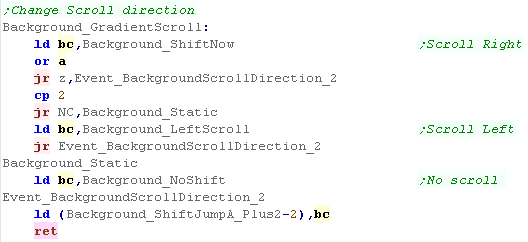
Set Scroll direction
| Depending on the scroll
direction, we may need to change the direction the gradient
moves, we use self-modifying code for this, and alter the bits
within the gradient definition. There are 3 options, Scroll Right, Left or no movement (inteded for vertical levels) |
 |
Background Gradient
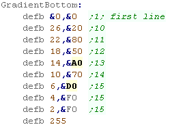
| First, lets remember what the
gradient definition looks like! The first two bytes are the starting pair... they are used for the first and second line... every other line is a new line number, and an extra byte for the gradient - this pushes out one of the old bytes, and the new pair is used. when a 255 is found, the gradient routine ends! |
 |
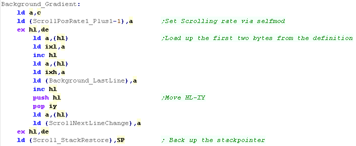
| When this routine is called, HL
points to the right of the top screenline... DE points to the
gradient definitions (as shown above), B is the linecount and
C is the bitmask of the scroll rate.. We use Self-modifying code to store the scroll rate at the correct point next we load in the first pair for the gradient - we load them into IXH and IXL... we also swap the source data pos into IY We also load in the 'next line' number - and self modify this in so we know when we need to read in more line data. We also back up the stack pointer - we're going to use stack misuse to draw to the screen quickly! |
 |
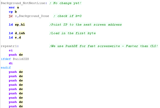
| We now start the main sequence,
first we check if we're at a 'new line' point.. .if we're not
then we skp to the 'rendering routine' If we do need to do a shift, first we check if the line byte is zero (blank area)... bitshifting zero makes no sense, so we skip if it is... If it's not, then we next check if the timer ticks ANDed with the scrollrate are not zero - if it's not, then we want to do a bitshift at this point, so we jump to the correct routine to do this (it will be altered by self-modifying code, depending on the scroll direction) |
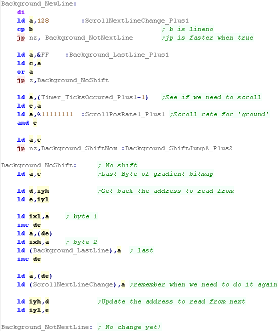 |
| The drawing routine starts by
checking the B counter, to see if we need to draw any more
lines... If B is not zero, we need to draw some more - we misuse the stack pointer to draw quickly to the screen, so we swap HL to the stack pointer... Next we set D and E to IXH - the first line byte of the gradient... We then need a lot of PUSH DE's to quickly draw to the screen! Note - on the CPC we keep interrupts enabled - the ChibiAkuams interrupt handler can cope with runing during stack misuse! |
 |
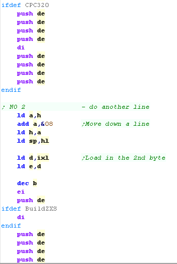
| While the interrupt handler can
cope with stack misuse, it won't work right unless there are a
few bytes for it to write to, so we disable interrupts before
the final push. We need to move down a line, because we know we're on an even line, we can simply add &8 to H - but we need to re-update the stack pointer The line drawing is done in pair, so once we've done the first line, we load in the fata for the second from IXL and repeat the procedure |
 |
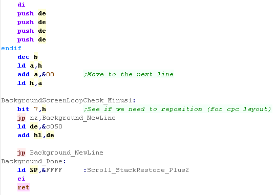
| For the finish up procedure, we
need to move down a line... however this time we need to check
bit 7, to see if we've gone over the bottom of the memory
range, and correct the HL position if we have. We now repeat the procedure again. The finishup procedure restores the proper stack pointer, turns interrupts on and returns. |
 |
| These
routines work in PAIRS - therefore a gradient change can
only occur on EVEN lines The routine is limited to make it as fast as possible, so many comprimises were made! |
 |
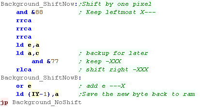
| The bitshift procedure is pretty simple, we need to pull out
the 2 bits that make up the rightmost pixel, shift the bits to
the left, and OR in the two bits - to put them in the left
hand pixel we store the result back into the memory which makes up the gradient definition |
 |
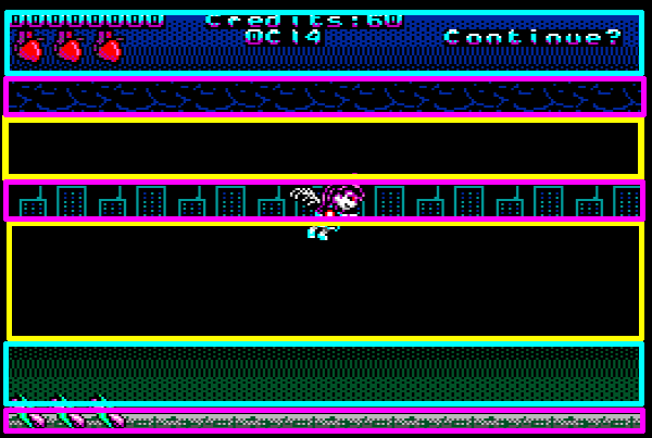
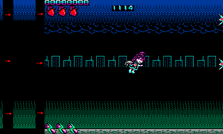
| Just like on the CPC, the MSX2
screen is drawn in 3 sections... the Gradient,
Solid Fills,
and Tile Fills.. Unlike the CPC though, on the MSX2, the Z80 draws the Gradient WHILE the VDP draws the fills and Tiles - We're doing 8 bit Multithreaded programming! |
 |
Drawing the TileMap
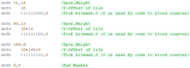
| When we call the Tilemap
drawing routine, we need to pass some parameters HL is the Tilemap Definition (example shown right) DE is the V9990 tilemap definiton (it can be more complex because the V9k is faster IX is the Gradient definition for the MSX2 - we'll look at that later |
 |
| The Background routine starts
with some special code on the V9K, which will switch in the
alternate definition - we do this here, because the level code
is common on both the V9K and MSX2 Now we need to load in the current screen position... the MSX2 screen will be at Ypos 0 or 256, depending on which framebuffer is shown, we then replace the low byte with the one read in from the definition, this gives us DY - our destination to show the tile to. Next we load in the number of lines to show, this is saved into NY The next one is a bit tricky, our tiles are saved as a block in the sprite data - and we need to load in the start of that block into this code (Via self-modified code) - we then add the Y offset of the current strip to that block Y offset - the result is the source Y - SY for the current strip. |
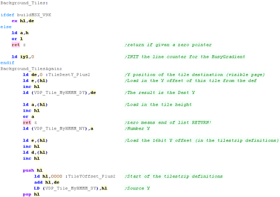 |
| You can see the Sprite data
here - in the Z80 coding bugs level, the Tiles should be at
the start, so the position will be calculated correctly
automatically |
 |
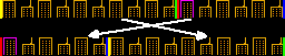
| Here's how the scrolling effect works. The tilestrip is split in two parts by the 'scroll point'... everything to the right is copied to the far left of the screen... everything to the left is put on the right... then the scroll point is increased... The result is a tilestrip the full width of the screen, which scrolls, and is filled with only 2 VDP commands (fewer commands= faster) |
 |
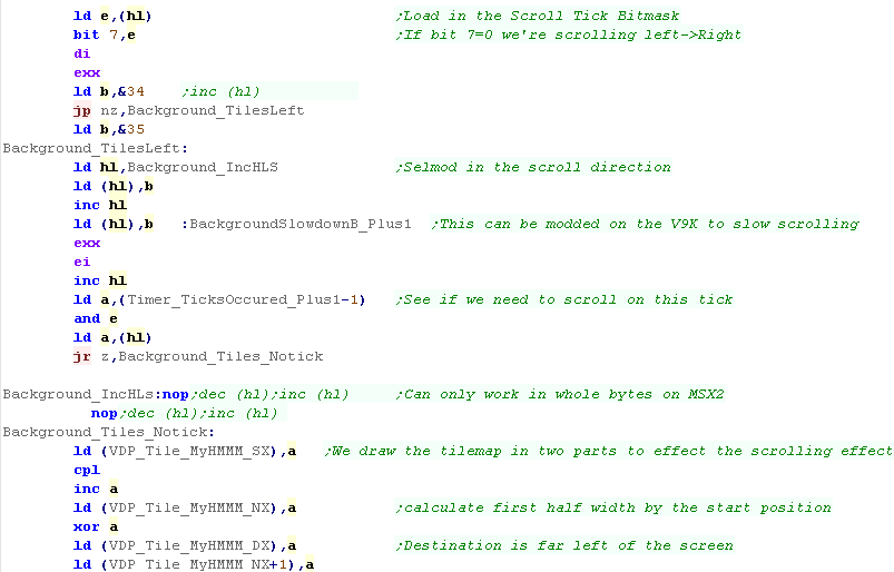
| Next we load in the
'Tickmask... the top bit will allow the scroll direction to be
reversed, the other bits are ANDed with 'TicksOccured'... this
allows the rate of the scroll to be altered It should be noticed there is a 'slowdown' section - this is used on the V9990, and is self modified to slow down the effect of the scroll The MSX2 VDP can only work in pairs, but the V9K can work in indevidial pixels, the two NOPS will be converted to INC (HL) or DEC (HL)s depending on the scroll direction. We're copying from the middle of the strip to the end - so the Width (NX) of the strip to copy is caclulated by flipping all the bits in the X pos (SX) the Destination DX is the far left of the screen, and we set the top byte of the NX to Zero. |
 |
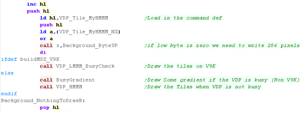
| Next we need to do a check on the number of pixels we're
going to draw... usually NX will be <255 - so a single byte
- but if the low bit is 0 - then we need to set the high byte
to 1... we do that now, buy calling the 'ByteUp' command,
which will increase the high byte by one... On the V9K we just draw the tilemap. On the MSX2 we run 'BusyGradient'... this checks if the VDP is busy, and if it is, then the Z80 will draw part of the gradient via memory access... we'll have a look at this command later. When the VDP is idle, we actually draw the gradient |
 |
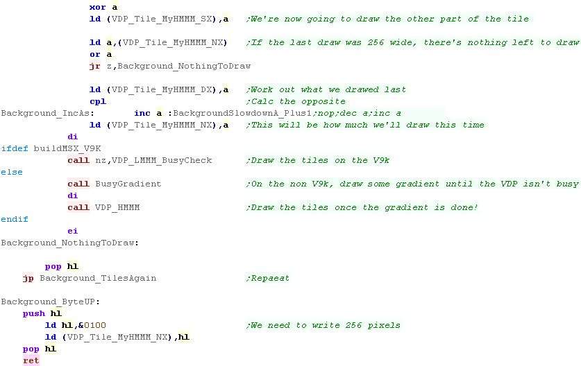
| We now copy from the start of the tile definition up to the
scroll point, so we zero SX We now load in NX and check if it was 256 - if it was, we've nothing more to draw, as we've filled the screen.... if not we use this as the destination of pixels to copy - effectively copying to the position the last copy ended. We do another CPL to work out how many pixels we need to draw to fill the remaining width of the screen Now we use the same routines as before, BusyGradient to draw any gradient while the VDP is busy, then we actually draw the tiles! We now repeat untill we've drawn all the tile definitions.. Finally we have the Byteup command - it just sets NX to 256, for the rare time we need to draw the full width in one go! |
 |
Solid Fill
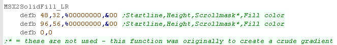
| The 'Solidfil' routine takes a definition table, each line
contains four bytes. The first byte is a Y position - this is where the fill starts. The second byte is a number of lines to be filled. The third byte is a 'tickmask' - this is not used for fills.. but originally this function was intended to perform crude MSX2 gradients the fourth byte is the fill color. |
 |
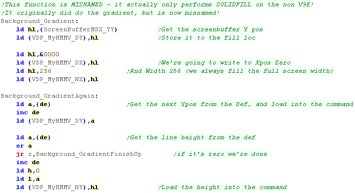
| The first thing to note is that
the solid fill routine is misnamed... it's called
'Background_Gradient'! This is because this routine WAS going to draw a gradient, but couldn't do a good job, so was demoted to solid fill! We're going to set up MyHMMV to solid fill the area... First we load in the Ypos of the drawing screen (DY) Next we set the starting Xpos to 0 (DX)... we set the width to 256 (NX) Now we load in the Y offset (one byte)... this is the start position (SX) Now we load in the number of lines - if it's Zero, we've ended the fill commands... otherwise we load it into the height (NY) |
 |
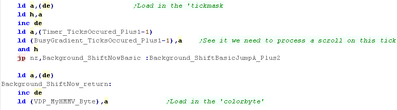
| We now load in a 'tickmask'...
this was used when this function drew gradients - and allowed
scrolling. Once we've done any scrolling (never happens!) we load in the color byte into the fill command |
 |
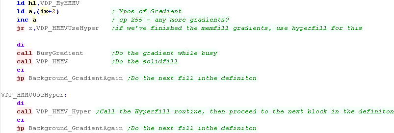
| Next we check IX... this points
to the 'true gradeint' definition - you see, the gradient is
drawn by the Z80 WHILE the VDP fills the blank areas... but if
the gradients are done, then we can use the Z80 to help fill the
blank areas with HYPER-FILL! If we have gradients to do, then we check if the VDP is busy, and draw gradients while it is using BusyGradient... which returns once the VDP is no longer busy... once the gradient is done we can do the fill... We now repeat the procuedure, untill all the fills are done! |
 |
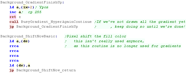
| The solid fills are done after
the tile fills... So once the solid fills areas are done, we see if all the gradient is drawn - and if it isn't we draw it until it is! |
 |
Gradient fill via Z80 ram access
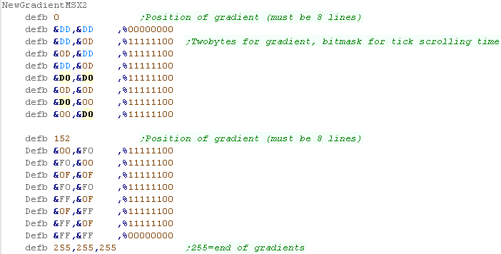
| When The Tile/Fill routines run,
IYL is initialized to 0 - this is the line number IX needs to be passed a table of gradient definitions... The definition starts with a line number - this is where the gradient is drawn... Then follows 8 lines... each line fills 4 lines of the gradient - MSX2 gradients are ALLWAYS 32 lines tall Each Line totals 3 bytes.. The first two bytes are the gradient color... there is also a 1 byte tick mask - this is when the scroll occurs. |
 |
| The BusyGradient should only run
when the VDP is busy - so first we check if it is... and return
if the VDP is idle... Next we flip into the shadow registers - these are used during by the gradient routine - allowing us to do two 'tasks' in paralell ( the Gradient and the Tile/Fill) We load in HL from the last time the gradient ran, and we see if the line number is Zero - if it is, then this is the first run... We load in a byte, and see if it's 255 - this would mark the end of the definition... otherwise we have gradient to draw! |
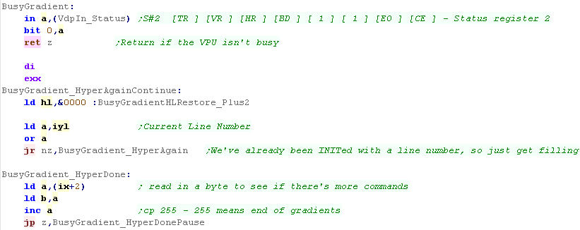 |
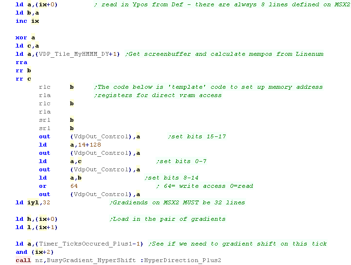
| We read in the Line offset from
the definition and store it in B, we load C with Zero, next we
get the drawing screenbuffer offset (0 or 256) and load it into
A We use these values to calculate, and set up the VDP Ram Access so we can do the ram access... Next we set IYL to 32 - this is the number of lines to draw... We load HL with the two bytes of the gradient, and compare the TickMask of the gradient with the ticks occured... if the result is NonZero we need to scroll the gradient on this tick |
 |
| We now fill a full line by OUTING the byte pairs to the DATA port of the VDP | 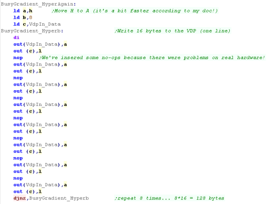 |
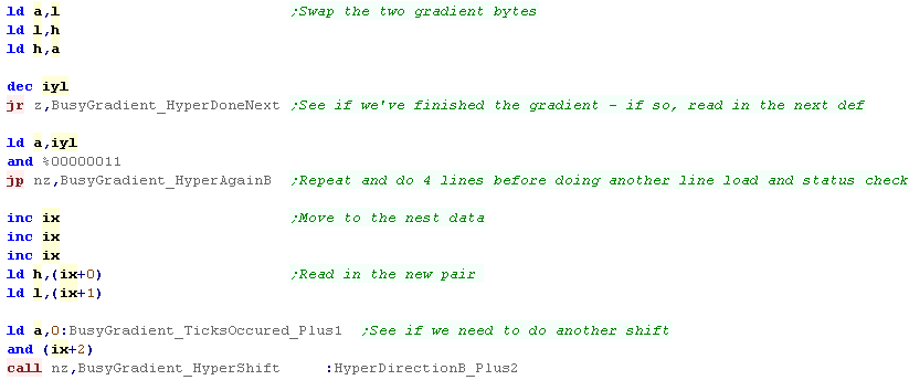
| We need to swap the two bytes
before drawing the next line... If we've drawn all the lines, we're done... otherwise we check if we've drawn 4 lines, if not then we repeat If we've drawn all the lines, then we load in the next bytepair and repeat the procedure. |
 |
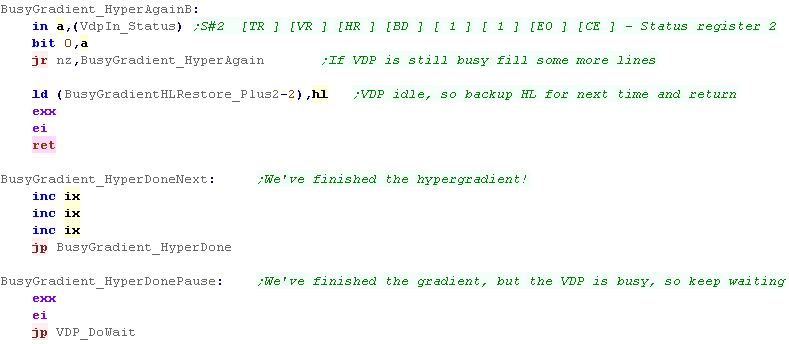
| We're going to repeat the draw
line procedure, but first we need to check if the VDP is idle...
if it is then we back up HL, flip the shadow registers
and return. We also have the "HyperdoneNext" routine which will load in the next stage of the gradient. |
 |
| We also have a bitshift routine which rotates the 4 pixels... this moves the leftmost pixel in L to the rightmost pixel in H | 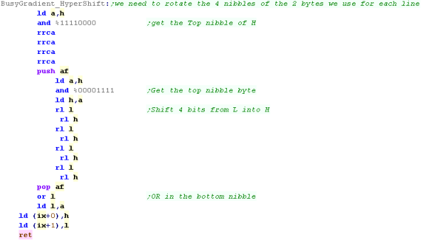 |
The theory!
| We start with a blank screen... our gradient procedure is: 1. Fill a strip 4 pixels wide, and 192 pixels tall with the gradient (on the left hand side) 2. Copy it over the whole screen 3. Add the tilestrips, sprites etc. |
 |
Drawing The Gradient
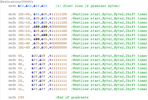
| The gradient is made up of 2 alternating line definitions -
of 2 bytes per line... The Gradient definition has to be passed in HL... The definition has a start line - which is the first two lines - each line takes 2 bytes... All following lines have a Line-number - a byte-pair for the new definition (which replaces the oldest of the two being cycled) and a shift timer -which is a bitmask used with 'ticks occured' to decide when to scroll the background Finally the last definition is ended by a 255 byte... |
 |
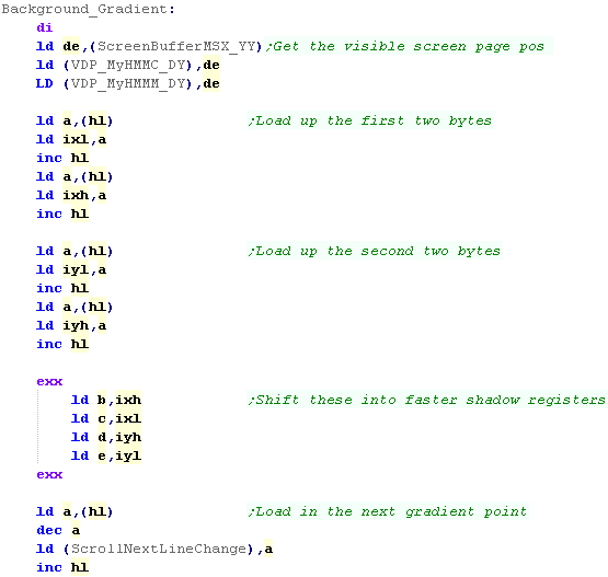
| When we call the routine, HL
will point to the gradient definition and B will be the line count (which is always 192) The first thing we do is INIT the destination ranges... we need to set the 'screen start Y', which will either be 0 or 256, depending on if screen buffer 0 or 1 is shown We now load in the two bytepairs for the first line.. we store them into IX/IY first - but we soon move them into the shadow registers BC/DE (which are faster) Then we load in the next point we need to change the gradient, and store it via self modifying code. |
 |
| We need to initialize two HMM
commands... one to fill the strip on the left (HMMC) and the
other to fill the whole screen with that strip (HMMM) Once we've set the command definitions up, we start the HMMC command. |
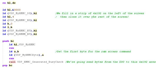 |
| We send 4 bytes to the VDP data
port - remember our strip is only 2 bytes wide, so this
effectively fills 2 lines! We now see if we need to do a gradient change - if not we jump over the next bit... Now we check if we need to do the Gradient scroll by ANDing in the 'Ticks occured' counter... if the result is not Zero, then we need to do a shift now! |
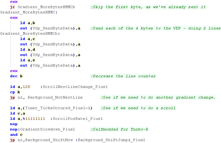 |
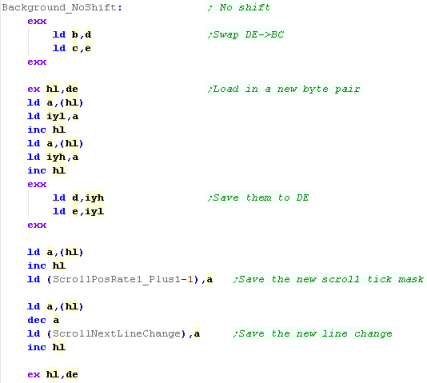
| When we need to load in a new
byte, we first swap DE into BC... then we load new bytes for
DE in from the source again We also load in the new scroll tick mask, and the next line we need to change the gradient again. |
 |
| Whether any updates are done or not - we decreace B and repeat until done! |  |
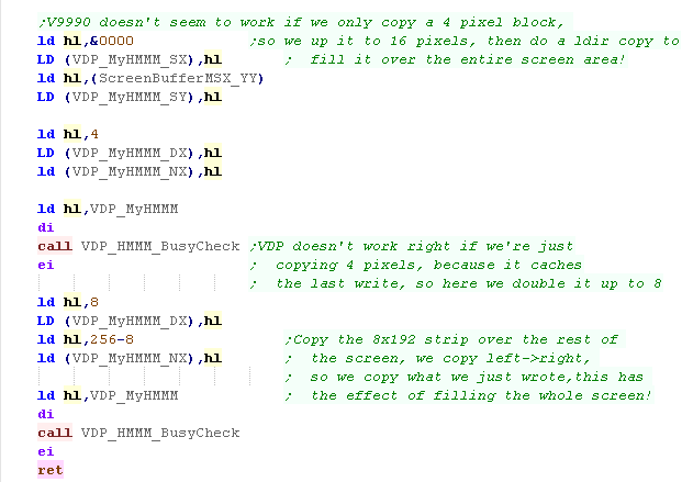
| We're going to copy a 252x192
area from the far left to the right... this results in the
copy command copying the 4 pixels repeatedly over the entire
screen.. In theory we'd just copy the 4 pixels across the screen, but in practace this doesn't work!... the reason for this is that the V9K is caching the bytes we just wrote... To counter this we double the 4x192 area to 8x192... then we copy this over the entire screen... The result is the gradient now fills the entire screen. |
 |
Scrolling the gradient data
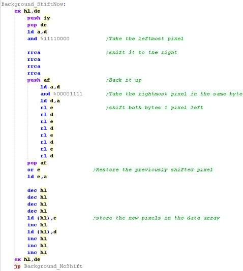
| The background pixel shift for
the V9K is almost identical to the MSX2... We take the rightmost pixel in the two bytes and shift it... Then we shift the other 3 left, and put the shifted first pixel at the far right. Once the bytes have been shifted, we save them back to the Gradient definition. |
 |
Level Init
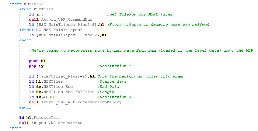
| On the MSX systems, we need to
initialize the memory locations of the Tile data used to draw
the background - the positions these need to go will have been
set by the previous load commands - however we need to
Self-Modify these into the code. Afterwards, we need to actually get the bitmap data... The data is RLE compressed, and it's bytes are stored in the level data block, so we decompress this from RAM into VRAM |
 |
| On the V9K on the MSX2 in Chibiakumas, boss battles uses custom sprites for enemy bullets, we need to load them in here. | 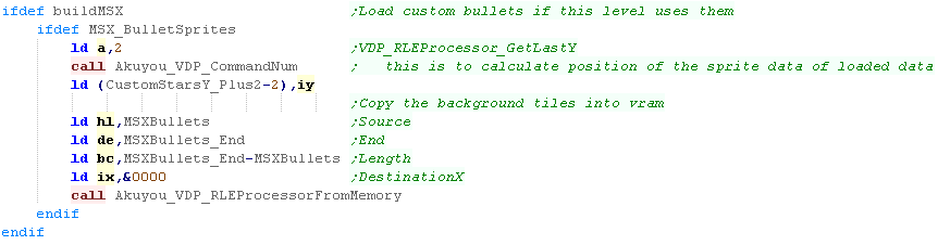 |
| For the next stage, we'll want the Player & game parameters. |  |
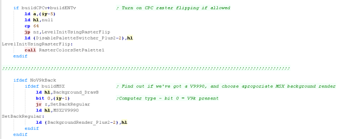
| Some levels of ChibiAkumas on
the CPC flipped colors every frame to 'fake in between'
colors... if the user allowed it it would be turned on here... On the MSX2 we would see if the V9K was present, and turn on the alternate background if it is. |
 |
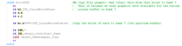
| On the Spectrum we have a
problem! the 2nd set of sprites are held in the level data,
but we need to page it out , and page in bank 7 for the second
screen buffer - which means we can't get access to the
sprites! To solve this, we copy the sprites into bank 7 where the second buffer is. |
 |
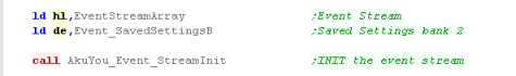
| Now we need to initialize the 'Event Stream' (the level
contents' HL points to the Event Stream data... DE points to a bank of ram which can be used by the event stream for an extra 16 object definitions (128 bytes)... it's not needed if you don't use "evtSettingsBankEXT" |
 |
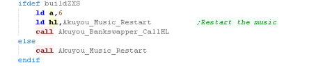
| Next we need to INIT arkostracker to get the music playing. Note that on the Speccy we use Bankswapper_CallHL - this function swaps the bank in, calls HL, and restores the level bank on the spectrum, so everything works OK |
 |
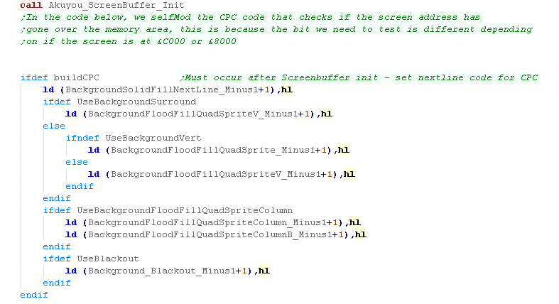
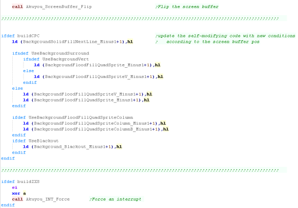
| We now initialize the screen
buffers - this sets up double buffering... Because of the memory layout of the CPC, and the fact we need to recalculate the memory location every time we go outside of the 16k bank of screen ram, we need to use self modifying code to change the conditions of the "Get Next Line" routines... HL will be set to the correct code by the ScreenBuffer_Init routine. |
 |
| Finally, we start the interrupt handler... The main level loop will now begin! |
 |
Level Loop
What is RLE?
| We need to draw everything in order, so first we draw the background. | 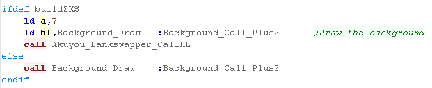 |
| We're going to do the level objects... first we calculate
any new level events via EventStream_Process... Next we draw all the level object with ObjectArray_Redraw |
 |
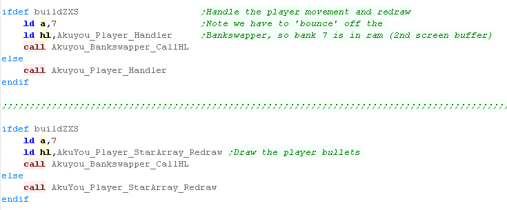
| We're going to start handling
the player... First we run the Player_Handler, this draws the player, and reads player controls. Then we execute Player_StarArray_Redraw, this draws the player bullets. |
 |
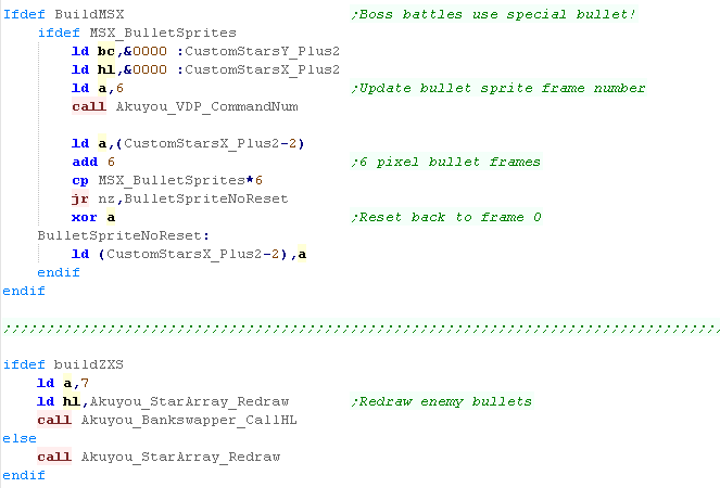
| We're going to draw the enemy
bullets... On the V9K boss battles we use animated sprites for bullets - we need to calculate which to use - they are 6 pixels wide, and we cycle through them for each frame of animation. Whether we're on the MSX or not, we now need to draw the enemy bullets with StarArray_redraw |
 |
| On the V9K we will draw an extra foreground layer... this is a tilestrip with transparency, and is handled by the same routine that handles the background code. |  |
| We've finished the drawing of the main level objects, so we now draw the UI (Scores/Lives etc) | 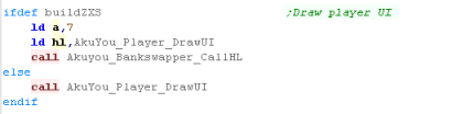 |
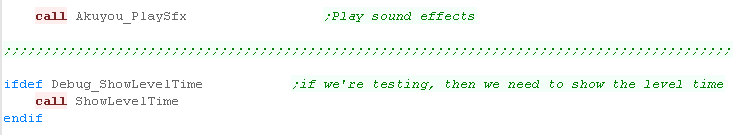
| We're pretty much done...
finally we play any sound effects Also, If debugging is enabled we'll show the current level time onscreen, so we can work out any problems with the event stream. |
 |
| At this point we'll do any 'Level specific' operations that need to occur before the page flip | |
| Now we do the actual page
flip... this shows the screen we just drew! On the CPC we now need to update all the GetNextLine commands again to take account of the change in the drawing page's memory position. On the Spectrum, we force an Interrupt to occur - this is because the drawing procedure is too slow, and is likely to have missed an interrupt - causing the music to slow down... we have to do this on the spectrum only, because unlike other systems, interrupts that occur when interrupts are disabled are missed, not delayed like on other systems. |
 |

What is RLE?
| RLE stands for Run Length
Encoding... this is a compression method where consecutive
pixels that are the same are compressed.. .by storing them as
a color and a count RLE is LOSSLESS - the image will be a perfect recreation of the original, but it will be slower to draw! Lets imagine we have a bitmap.... and the pixels are colored 122222222221111111123 ... that's 21 characters.... Now let's imagine we stored that as 1x1.2x10.1x8.2x1.3x1... that's 19 characters Now that's a ridiculous example, but the principle stands - and rather than characters, we'll store our data in Nibbles (half bytes) |
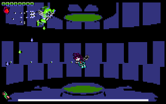
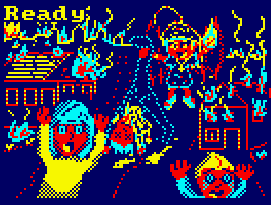
Rle Bitmap shown on the CPC!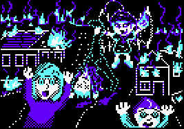 |
With the right data, RLE files are much smaller than raw bitmaps, and because the compressor 'understands' image data, they can beat compressors designed to work with byte data (an RLE compressor can save space on 5 consecutive pixels the same color, a byte compressor cannot) One thing to bear in mind, the resulting RLE will be more efficient if lots of consecutive pixels are identical, and you can use this in your art design if you need to save space! |
A file optimized for RLE - note the grey and black 'lines' and few single pixels These compress better than a checkerboard 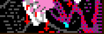 |
How does ChibiAkumas format it's RLE images?
Data is stored in bytes, but these bytes are split into 2 nibbles - and depending on the data, the pixels will be drawn accordingly... on the CPC, one nibble is 2x Mode1 pixels - and we work in Pixel Pairs - this is because the chibiakumas graphics will often use 'checkerboard' (alternating 2 pixel colors) to simulate other colors - and the RLE compressor is designed to compress that!
| Bits | Meaning |
| RRRRCCCC+ | C repetitions of RLE data R if C=16 then read in the next byte and add to count... if that's 255 read in the next byte too!!) |
| CCCC0000+ BBBBBBBB.... BBBBBBBB | C bytes of linear (uncompressed raw) byte data (there are C x bytes of B) (C can be more than byte when 16/255+) |
| 00000000 CCCCCCCC+ BBBBBBBB | C repetitions of Byte B (all bytes are the same color... C can be more than one byte when 255+) |
| Why
so many options? COMPRESSION! Not all data is RLE compressible - and trying to compress it will make it bigger... so we have a 'linear' option to resolve this... Also writing lots of bytes of the same color is slow - so we have a 'repeated byte' option too! |
|
Creating an RLE!
| My free, open source AkuSprite
Editor can create RLE files for the CPC, Spectrum, MSX and Sam
Coupe... the file format is basically the same, but because of
the different bit depths of the machines, the number (and
order) of the pixels compressed differers... on the Spectrum
the color information is also RLE compressed as an extra data
set. It should be possible to write decompress ors for the other systems, however it is not my plan to do so at this time, as I have no plans to use RLE on other systems at this time - and porting the decompresser is time consuming. |
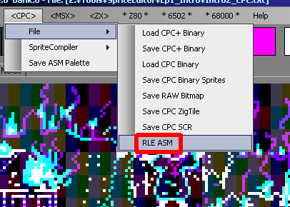 |
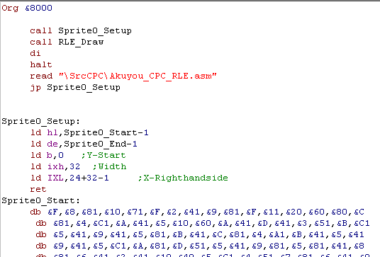
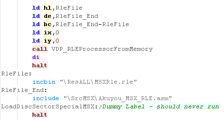
Using RLE on the CPC
| When we use the RLE function,
the RLE sourcecode is stored into the clipboard... If we just add an ORG &8000 we can compile the code, and just do a CALL &8000 to show our RLE... Note, the color information is not stored in the RLE, so we'll need to set the palette ourself! Also Note, this example has a DI, HALT at the end - so we'll need to change this depending on what we want to do! |
 |
| If we want to use the CPC
firmware (for example to return to basic, we need to make some
changes! The firmware relies on the shadow register BC being unchanged, so we need to back that up! By adding an EXX and PUSH/POP of BC, we can keep the firmware happy! |
 |
 |
The
compressor was designed for the CPC, but was ported to the
other systems, on the speccy each nibble is 4 pixels - on
the MSX/SAM it's just one! Basically the decompresser is the same though, just with code reprogrammed for screen pixel drawing, and the 'GetNextLine' command is changed |
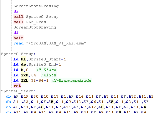
Using RLE on the Sam Coupe
| The RLE export for the SAM is
basically the same, we need to add some extra commands to
page in the video ram, but otherwise it's the same like the CPC, the palette is not included . |
 |
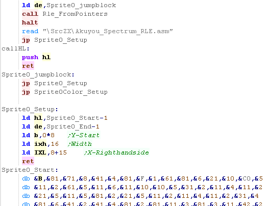
Using RLE on the ZX Spectrum
| The Spectrum RLE export is
basically the same, it will export code that you can just go
ahead and run. you should note that the decompresser uses the IY register - again, this is needed by the Spectrum firmware, so you'll need to back it up if you're using the speccy firmware. |
 |
Using RLE on the MSX
| The MSX version is the 'odd one out'... Rather than saving the RLE to the clipboard, it is saved to a file - this is because the MSX screen is very large (24k), and the ram is very small (64k)... also the disk is relatively slow..., For this reason ChibiAkumas usually streams RLE from the disk to the VDP without using ram - this ends up faster, and doesn't use any memory (well technically it uses a 128 byte buffer) However, when we use the export routine in Akusprite editor, a simple 'Loader' will be created which does allow the RLE to be viewed from ram, This can just be pasted in and should run OK, provided your screen is set up correctly, and you have the 'VdpMemory.asm' module included - which handles the VDP init commands for the RLE draw |
 |
| The
ChibiAkumas RLE format probably isn't the best - but it's
FREE... Chibiakumas was developed for personal achievement by the developer, and the author wanted to try to make his own RLE compressor - being the best or fastest wasn't the mission! |
 |
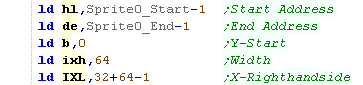
Initialization routine
| As we saw before, When the RLE decompresser is started HL
points to the start of the data in RAM, DE points to the end,B
points to the Y line to start drawing, IXH is the width
in bytes, and ITL is the X pos of the RIGHT HAND SIDE.... This is because the decompresser works Right-> Left, this was to allow the option of using stack misuse for filling. |
 |
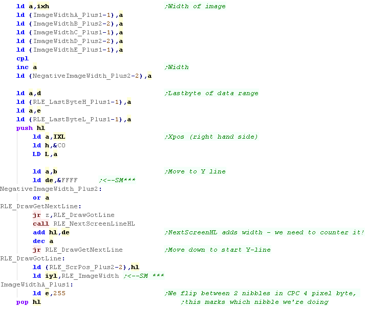
| First we need to initialize
various parameters using self modifying code... Next we need to calculate the starting screenpos, we use the NextScreenLine function to do this, but it automatically adds the image width (as it's designed to recalculate the starting line during drawing) so we need to subtract that width for each iteration Once we're ready we set E to 255 - E is used during drawing RLE data to mark which half of the byte is currently drawn - as each RLE nibble is 2 pixels there are two iterations per screen byte. Once set up is done, we're ready to draw our RLE! |
 |
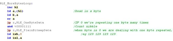
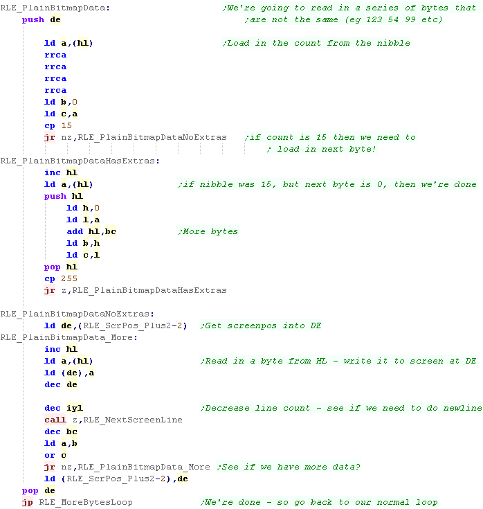
The main loop
| First we check what kind of
data we have ....as discussed before, the second nibble is the
RLE count... if the count is zero - then this byte is linear
data. Otherwise we store the count for later |
 |
RLE Data
| Now we load in the pixel
data... two visually consecutive pixels on the CPC are not
consecutive in RAM. To optimize the RLE compression we store in the file according to the visual layout, and bitshift into the correct position for the screen now. We also check the count... if the count is 15 (all bits of the nibble are 1) we read in the next byte as well, and add it to the count... if that byte is 255 then we keep reading in bytes and adding them to the count until one isn't! |
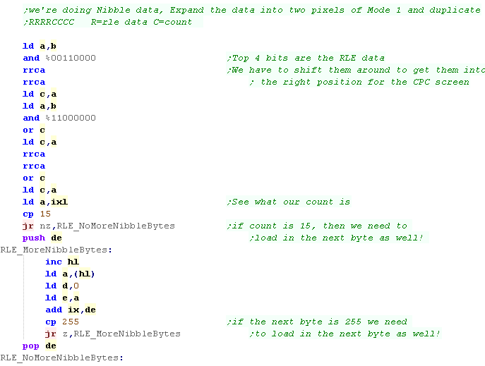 |
| We're going to fill the bytes
of the screen with the nibble we read in, we have two versions of the code, so that whatever the position we need to plot our pixel pair to video ram, we can do so. If we've completed a line of the RLE, we recalculate the position of the start of the next line. We check IX to see when we've completed all the drawing for this RLE batch - once we're done we back up the screen pos of the current draw Note 'ByteNibbles' this is a special routine that will fill entire bytes with the nibble for extra speed. |
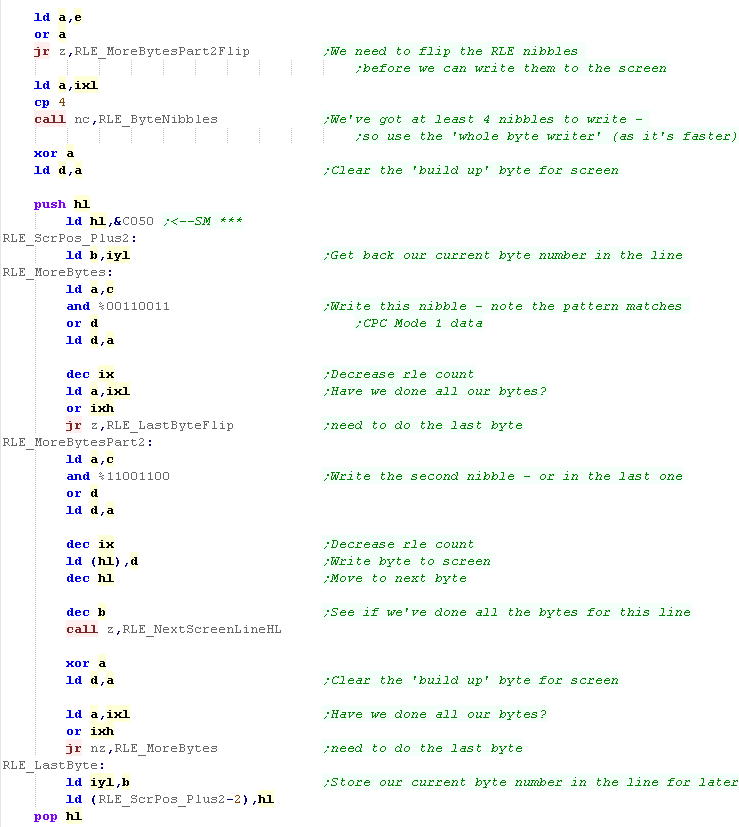 |
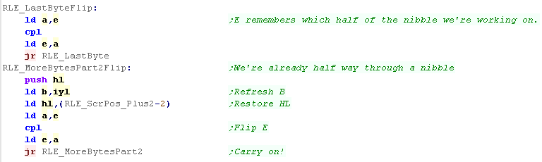
| We need some commands to allow
for the starting of RLE data half way through a screen byte. These commands handle this, flipping E (the current nibble selection), and jumping to the middle of the loop |
 |
 |
On the
MSX each RLE nibble is just one pixel... on the Speccy
it's 4 pixels - also, on the speccy the format is simpler,
as unlike the CPC, the pixels on the speccy are
consecutive - so the code that shifts the bits is
different. |
Nibble pairs (Full bytes)
| If there is a lot of RLE data
left, it's faster to fill it in bulk, so we do that with the
ByteNibbles function It's essentially just copies the C byte to the screen, decreasing the count by 2 each time, until theres only 3 nibbles left, then we switch back to the regular routine |
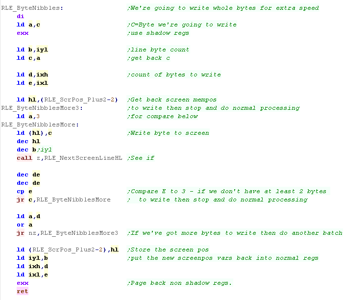 |
 |
The
nibble pair code is just a speedup! You could remove it and the regular RLE code could do the job, the drawing would just be significantly slower. |
Byte Series Data
| If the 'RLE count' nibble is
zero then the top nibble is a count for a series of bytes to
be shown to the screen This is where we could not compress the data as an RLE, so we're storing it 'As Is' we need to shift the top nibble to the bottom, then (as before) if the count is 15, we load in more bytes to get the total count. Once we've got our count, we start reading bytes from the source, and writing them to the screen, checking for a newline until we've done all the bytes |
 |
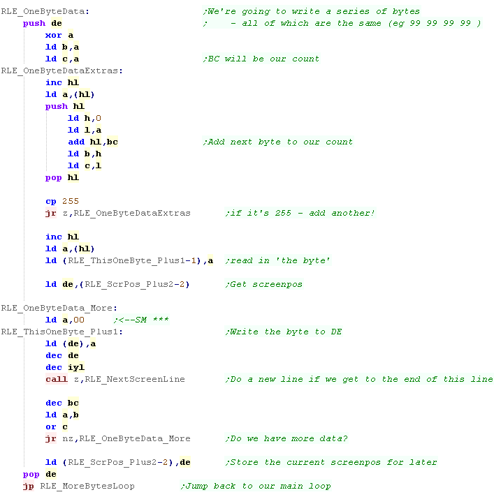
Repeated Byte Data
What is a 'Compiled Sprite'
Creating Compiled sprites for the CPC
Creating Compiled sprites for the ZX Spectrum
Starting the draw
Fast filling with PUSH
| There will be many times
where a large area is filled with a single repeating byte,
although that byte may not be RLE compressible (eg 4
different colors repeated)- we have a special routine to
handle this! This is defined by the first byte being zero - so the count is entirely in the following bytes. Once we have the count ,we just copy bytes accordingly , checking for a new line as usual |
 |
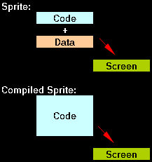
What is a 'Compiled Sprite'
| A normal sprite will have
some kind of Bitmap data, and some Code... the Code reads in
the Bitmap data, and 'Draws' the sprite to the screen A Compiled sprite is different... there is no Bitmap Data to read in... the sole purpose of the code is to draw that one sprite...and it's optimized to do that job as fast as possible! Effectively a compiled sprite is an ASM program, and AkuSprite Editor can produce the code to show the sprite for us! |
 |
| In ChibiAkumas, Compiled sprites are used for the
background of the last level of EP1, and the 'Sakuya' battle
of EP2 - which had a pre-rendered 3D background with up to 8
frames on repeating animation... Completely redrawing a full screen each frame during gameplay takes a lot of CPU power, so this is a time Compiled sprites are needed... The Compiled sprites in ChibiAkumas do have some bitmap data... this is because a pure compiled sprite of a complex 16k screen could easily end up as greater than 64k! In this episode, we'll learn how to make and use compiled sprites for the CPC and ZX spectrum... Because direct memory access is slow on the MSX, compiled sprites are not possible on the MSX! |
 |
| RLE
is good when you need the space, and can spare the CPU
power... Compiled Sprites are for when you need the CPU power, and can spare the space... In both cases, it's unlikely you're going to be able to clip the sprite (have the sprite partially onscreen) so they're really best for 'special cases' |
|
Creating Compiled sprites for the CPC
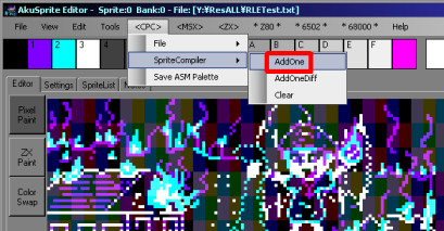
| We're going to convert the same bitmap we used in the RLE
example... We just load the picture we want to convert into AkuSprite editor... and select the AddOne menu option... the source code is copied into the clipboard This will add an extra frame to the compiled sprite data (multiple frames can be combined into one code file)... AddOneDiff adds the difference between the new frame and the last one - effectively a transparent layer. Clear will remove all the compiled sprite data. |
 |
| We can paste the compiled
sprite code into Winape to execute it... We do need to make a few changes first... |
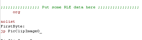 |
| Delete the incomplete ORG statement | 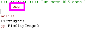 |
| Remove the last EI command from the EndCode - the Firmware interrupt handler won't like it. | 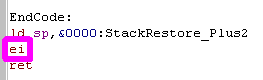 |
| To keep the firmware happy,
we need to change the first Jump
to a Call,
and backup shadow BC This will produce a program we can run from basic. |
Before: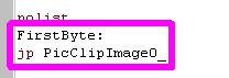 After: 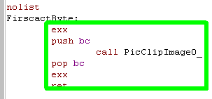 |
| We can show the sprite by
typing "Call &8000"
from basic. The sprite will be shown - much faster than the RLE - and basic will continue working. |
 |
Creating Compiled sprites for the ZX Spectrum
| Just like on the CPC, we can use the 'AddOne' option on the ZX Spectrum to add an extra frame to the compiled sprite | 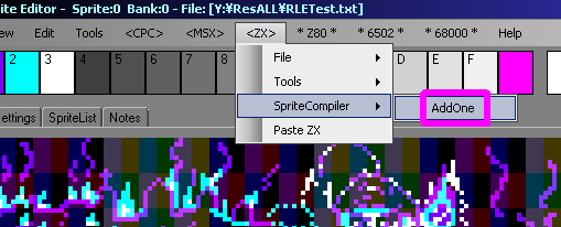 |
| After we paste in the clipboard, we need to delete the first ORG Statement | 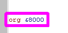 |
| We need to change the start Jump
to keep basic happy. We need to change it to a Call, and back up IY... |
Before: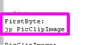 After: 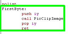 |
| The Compiled sprite generator has made a mistake, it
didn't define MultiPushDE31... we can fix this though! |
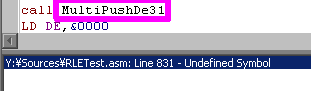 |
| If we make MultipushDE31 using MultiPushDE40 as a template the problem will be fixed | 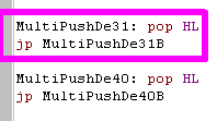 |
| The compiled sprite will be shown to screen, and basic will continue working! | 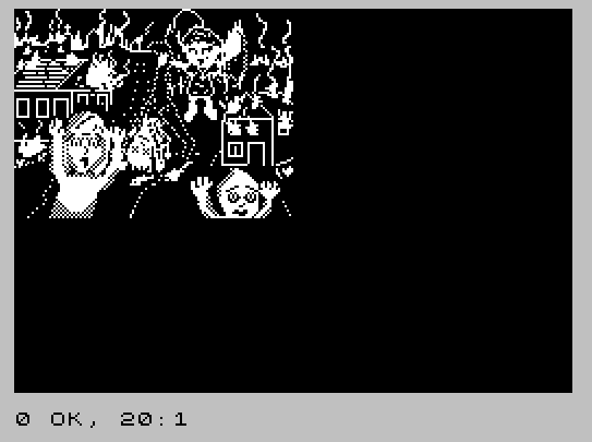 |
|
Akusprite
Editor also does speccy colors, so you can do a
full-screen full color background... This was used in ChibiAkumas EP1 V1.666 during the last boss battle for the background. |
Starting the draw
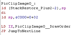
| The start point of the Compiled sprite is pretty simple...
we use Stack Misuse to get data to the screen as fast as
possible... this is where we use PUSH commands to write
bitmap data to the screen. We first need to back up the real stack pointer, then point SP to the right hand side of the top line of the destination... Next we load IX with a pointer to the DrawOrder line list, and execute 'JumpToNextLine' which will handle the draw |
 |
| The DrawOrder is a set of pointers to sections of code... the idea is that many images will have repeating parts, and we can use the same code to draw multiple lines... unfortunately this image has no such lines, so it doesn't save space - but usually it will! | 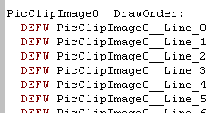 |
| When we start drawing a line, we load in the address of that line code, and jump to the code. | 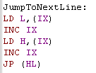 |
| The DrawOrder list allows us to reuse lines to save space, however this still needs 400 bytes for a full 200 line screen... if many of the lines are the same (eg if much of the screen is blank) we can use a Looper... this will repeat one or two lines a certain number of times, allowing for a smaller DrawOrder table to fill the screen. | |
Fast filling with PUSH
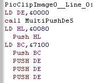
| Because PUSH is the fastest way to fill the screen we use
it for the fill.. The first few bytes are all blank, so we load DE with &0000, and use 'Multipush' to do the fill... this is a set of PUSH DE commands... even though we're misusing the stack, we can use a CALL here, as we've got two bytes left to draw, and the code is designed to work around this... we'll look at this in a moment... The next bytes we need to write are &0080 - we use HL.. then we want to write &7100 - we use BC... Now we want to write $0000 again... the compiler knows DE still contains this, so we can just PUSH DE again! |
 |
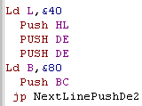
| We now need to write $0040... HL still contains $0080...
so if we just change L to $40, we'll have the right value to
push... We need some more $0000's... and DE still contains that value... we also need $8000... BC contains $7100, so if we change B to $80 we'll have the value new need... Finally we need to push 2 DE's, and then we've completed the line |
 |
|
The C# Sprite Compiler remembers the
current state of each register, and trys to use the best
way to produce the new value we need... this can be
setting part of the register with commands like LD
L,&xx or copying parts of other registers like LD L,B It's just a case of finding the simplest way to get the resulting pair to PUSH to save speed, and space! |
MultiPush
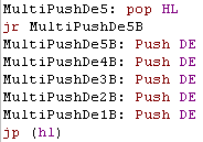
| We CALLED MultipushDE5... we're going to push bitmap data to
the screen, so we need to get that return address out of
there... we pop it into HL, and then do the 5 pushes... Once we've done, we effectively return, by Jumping to the address in HL that we popped earlier |
 |
| The NextLinePushDE2 is just a pair of DE pushes... but execution falls into the code to calculate the start of the next screen line, and then falls into the jump code which runs the drawing routine for the next line | 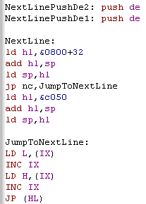 |
| The NextLine
Command will need to be modified if you're intending to use
a second screen buffer, You will also need to reprogram the code if you want to reposition the sprite |
|
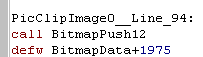
Bitmap data... when Push doesn't
work
| Writing 2 bytes of data with "LD HL,&xxxx... PUSH HL"
takes 4 bytes... so in the worst case scenario we're
doubling our data size... a serious problem when our screen
is 16K and our ram is 64K! Unfortunately, we do have to use some bitmap data to stop the program getting too large - we only do this where PUSH commands aren't helping at all... We can call BitmapPush to do this... the following 2 bytes after the call are the address of the data. |
 |
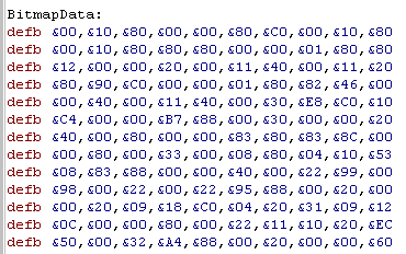
| The bitmap data is... well... bitmap data! The C# Compiler remembers all previously defined data, and if it's possible to 'reuse' some that's already defined, then it will! |
 |
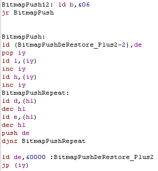
| Before we jump to the BitmapPush itself, we set B to the
number of WORDS of data we want to copy... We back up DE... it may contain useful data we'll want to push again later. Next we POP the return address into IY, and load in the address of the calling function... we read in the following 2 bytes.. these are the address of the bitmap data. Now we read in a bytepair from the bitmap data and PUSH it... we repeat until B reaches zero, then we restore DE and return. |
 |
|
We often
try to combine the last command with the next line command
with functions like " jp NextLinePushHl " Because these commands will be used often, we can save a byte or two with the last command in this way. |
| View Options |
| Default Dark |
| Simple (Hide this menu) |
| Print Mode (white background) |
| Top Menu |
| ***Main Menu*** |
| Youtube channel |
| Patreon |
| Introduction to Assembly (Basics for absolute beginners) |
| Amazon Affiliate Link |
| AkuSprite Editor |
| ChibiTracker |
| Dec/Bin/Hex/Oct/Ascii Table |
| Alt Tech |
| Archive.org |
| Bitchute |
| Odysee |
| Rumble |
| DailyMotion |
| Please note: I wlll upload more content to these alt platforms based on the views they bring in |
| 68000 Content |
| ***68000 Tutorial List*** |
Learn 68000 Assembly  |
| Hello World Series |
| Platform Specific Series |
| Simple Samples |
| Grime 68000 |
| 68000 Downloads |
| 68000 Cheatsheet |
| Sources.7z |
| DevTools kit |
| 68000 Platforms |
| Amiga 500 |
| Atari ST |
| Neo Geo |
| Sega Genesis / Mega Drive |
| Sinclair QL |
| X68000 (Sharp x68k) |
| 8086 Content |
| Learn 8086 Assembly |
| Platform Specific Series |
| Hello World Series |
| Simple Samples |
| 8086 Downloads |
| 8086 Cheatsheet |
| Sources.7z |
| DevTools kit |
| 8086 Platforms |
| Wonderswan |
| MsDos |
| ARM Content |
| Learn ARM Assembly |
| Learn ARM Thumb Assembly |
| Platform Specific Series |
| Hello World |
| Simple Samples |
| ARM Downloads |
| ARM Cheatsheet |
| Sources.7z |
| DevTools kit |
| ARM Platforms |
| Gameboy Advance |
| Nintendo DS |
| Risc Os |
| Risc-V Content |
| Learn Risc-V Assembly |
| Risc-V Downloads |
| Risc-V Cheatsheet |
| Sources.7z |
| DevTools kit |
| MIPS Content |
| Learn Risc-V Assembly |
| Platform Specific Series |
| Hello World |
| Simple Samples |
| MIPS Downloads |
| MIPS Cheatsheet |
| Sources.7z |
| DevTools kit |
| MIPS Platforms |
| Playstation |
| N64 |
| PDP-11 Content |
| Learn PDP-11 Assembly |
| Platform Specific Series |
| Simple Samples |
| PDP-11 Downloads |
| PDP-11 Cheatsheet |
| Sources.7z |
| DevTools kit |
| PDP-11 Platforms |
| PDP-11 |
| UKNC |
| TMS9900 Content |
| Learn TMS9900 Assembly |
| Platform Specific Series |
| Hello World |
| TMS9900 Downloads |
| TMS9900 Cheatsheet |
| Sources.7z |
| DevTools kit |
| TMS9900 Platforms |
| Ti 99 |
| 6809 Content |
| Learn 6809 Assembly |
| Learn 6309 Assembly |
| Platform Specific Series |
| Hello World Series |
| Simple Samples |
| 6809 Downloads |
| 6809/6309 Cheatsheet |
| Sources.7z |
| DevTools kit |
| 6809 Platforms |
| Dragon 32/Tandy Coco |
| Fujitsu FM7 |
| TRS-80 Coco 3 |
| Vectrex |
| 65816 Content |
| Learn 65816 Assembly |
| Hello World |
| Simple Samples |
| 65816 Downloads |
| 65816 Cheatsheet |
| Sources.7z |
| DevTools kit |
| 65816 Platforms |
| SNES |
| eZ80 Content |
| Learn eZ80 Assembly |
| Platform Specific Series |
| eZ80 Downloads |
| eZ80 Cheatsheet |
| Sources.7z |
| DevTools kit |
| eZ80 Platforms |
| Ti84 PCE |
| IBM370 Content |
| Learn IBM370 Assembly |
| Simple Samples |
| IBM370 Downloads |
| IBM370 Cheatsheet |
| Sources.7z |
| DevTools kit |
| Super-H Content |
| Learn SH2 Assembly |
| Hello World Series |
| Simple Samples |
| SH2 Downloads |
| SH2 Cheatsheet |
| Sources.7z |
| DevTools kit |
| SH2 Platforms |
| 32x |
| Saturn |
| PowerPC Content |
| Learn PowerPC Assembly |
| Hello World Series |
| Simple Samples |
| PowerPC Downloads |
| PowerPC Cheatsheet |
| Sources.7z |
| DevTools kit |
| PowerPC Platforms |
| Gamecube |
| Work in Progress |
| ChibiAndroids |
| Misc bits |
| Ruby programming |
Buy my Assembly programming book
on Amazon in Print or Kindle!


Available worldwide!
Search 'ChibiAkumas' on
your local Amazon website!
Click here for more info!


Buy my Assembly programming book
on Amazon in Print or Kindle!
Available worldwide!
Search 'ChibiAkumas' on
your local Amazon website!
Click here for more info!
Buy my Assembly programming book
on Amazon in Print or Kindle!
Available worldwide!
Search 'ChibiAkumas' on
your local Amazon website!
Click here for more info!