

Platform Specific Series
In this series we'll look at the PDP-11 and UKNC, and look at various tasks on the hardware, such as drawing graphics, reading keys, and working with RAM.
PDP-11 Platform Specific Lessons


| The PDP-11 was a old Terminal style server, Unlike a modern
computer with a keyboard an screen plugged straight into the CPU
tower unit, the PDP-11 did not... instead a Terminal console would
be connected to the computer, The console would send keypresses as
ascii - and read back letters and control codes - and it's the
terminal that would interpret these into a text screen. That's how the PDP-11 worked. The UKNC took it's inspiration from the PDP-11... and it's compatible with the PDP!... however the PDP-11 DOES have a screen and keyboard The UKNC is simulating a Terminal, and sends keys and receives graphics in the same way as the real PDP-11 We can use the same ports and codes on both - the basic text example will work on either the UKNC or PDP-11  The UKNC has a keyboard and connects to a monitor |
 The PDP CPU unit - no screen or keyboard! 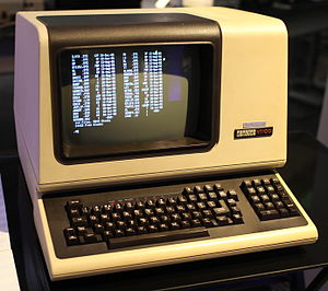 The Terminal is as big as a computer itself! |
| The PDP-11 machines use two pairs of ports... There are two for reading the keyboard... and two for writing to the screen! Why two? Well there's a status port, and a data port for each! |
 |
| We're going to use 4 ports... On the PDP-11 these will send data to the Terminal On the UKNC these will send commands to the PPU Peripheral cpu - which will simulate a terminal... Either way the effect of these is the same |
|
||||||||||||||||||||
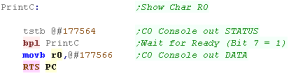
| When we want to send a character to the
screen (PrintC) we first need to check if the port is ready to
take data... We do this by testing 177564 (in octal) ... this sets the flags... if the top bit is 0 we're not ready - and BPL will occur - to wait until it is 1 We then send our byte to 177566 - it will be shown to the screen |
 |
||||||||||||||||||||
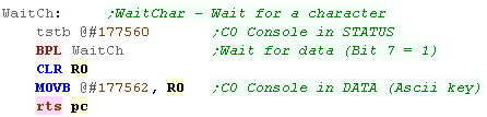
| The procedure is similar for Reading a character. We first test port 177560 (in octal)... this sets the flags - if top bit is 0 then no key has been pressed... we're going to wait for a key, so we branch with BPL to wait until it becomes 1 We then read in a byte from 177562 - this is the key that was pressed! |
 |
 |
If we want to
do things like move the cursor around (LOCATE in basic) we can
do this with ANSI escape sequences, the PDP TERMINAL/UKNC will
process these and show the result. Find out about them here... The UKNC also has some special ones we'll learn about later! |
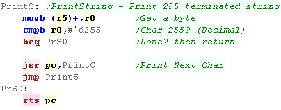
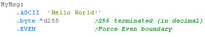
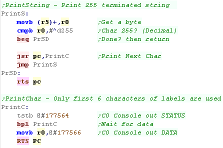
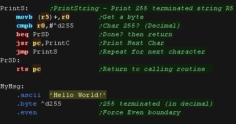
| Here we're going to read in a string from R5 we use 255 termination in these tutorials... we read each character until we get a 255 - sending each to PrintC to show it to the terminal |
  |
| If we want to start a new line we do this by sending Char 13 (15 in Octal - Carriage Return) then Char 10 (12 in octal - New Line) | 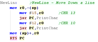 |
| The Hello World example also includes 'Monitor'
Functions - these show the contents of the registers, and bits of
memory. We just use .INCLUDE /Monito.mac/ to include these functions... how do they work? Well they're complex, so we're not covering them here! - sorry! |
|
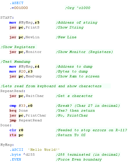
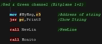
| First we're going to show 'MyMsg' to the screen - This will
print our 'Hello World' message... we call PrintS
with the message address in R5 Then we'll start a new line by calling NewLin Next we'll call Monitor - this shows our registers to the screen. Next we'll use MemDump - this shows R3 bytes of memory from address R4 Our final test will repeatedly read characters from the keyboard into R0 with WaitChar - and show them with PrintChar we do this until we get a char 27 (33 in octal) - this is the Escape key |
 |
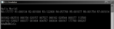
| Here's the running example on the PDP-11 |
 |
| Here's the same code running on the UKNC | 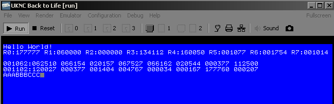 |
| On the PDP-11 There are Three stages to compiling our
program.... 1.First we Build our file by runing MACRO-AS on our R11 emulator... here the file we're build is '%BuildFile%' (this is run in a batchfile)  2.Next we need to LINK the file created by stage 1- this turns it into a SAV - which is a file that can be run with the PDP-11  3.Finally we start R11 with the created SAV file - this runs it on our R11 emulator!  |
| On the UKNC there is a fourth stage... 1.First we Build our file by runing MACRO-AS on our R11 emulator... here the file we're build is '%BuildFile%' (this is run in a batchfile) 2.Next we need to LINK the file created by stage 1- this turns it into a SAV - which is a file that can be run with the PDP-11 3. We convert the SAV file to a cartridge with Sav2Cart  4. Finally we load the UKNC emulator and boot it to the cartridge (the settings already have it mounted)  |
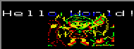
Here's Chibi!
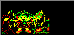
| In this lesson we'll show our mascot "Chibiko" to the screen... The image is using 2 bitplanes (1+2), but the "Hello World" Text uses all 3, so where we overwrote it, it turned blue (Bitplane 0) |
 |
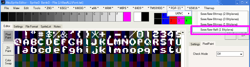
| My AkuSprite Editor can output ASM source in the format you need for the UKNC | 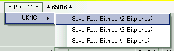 |
| We're including out sprite data as ASM source. | 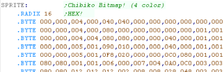 |
Setting up our screen
| We're going to send special 'control codes' to the terminal to
configure the screen. To do this we've defined a PrintChar, and PrintString function. |
 |
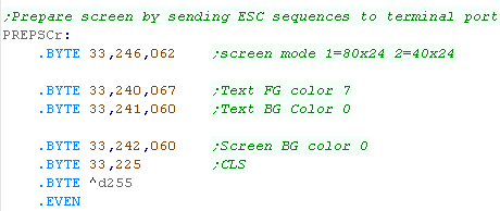
| We're using special 'ESCape' codes - Char 33 is the escape code
(33 Octal = 27 decimal)... characters following this reconfigure the
hardware, Here we've changed the screen mode, the Text colors, and the background color, before clearing the screen. |
 |
| We send this string to the terminal with our printstring command. | 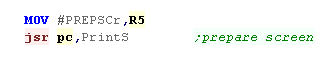 |
Physical addresses and RAP ports
| By default VRAM is set to addresses 100000+, but this memory isn't
accessible from the Main CPU.
We can use a device called the 'RAP' to access this, using this the Main CPU can access 2 bitplanes (Green and Red) - but still can't access Bitplane 0 (Blue) We select the VRAM address from the MAIN CPU using port 176640, we then write bytes to VRAM with ports 176642 and 176643, which will write our bitmap to the Green and Red bitplanes |
CPU RAP Address select port: 176640
|
||||||||||||||||||||||||||||||||||||||||||
Drawing our sprite to the screen
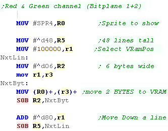
| In this screen mode, each line has 80 bytes, and the screen base
is 100000. The formula for our sprite position is: 100000 + (Ypos* ^d80) + Xpos |
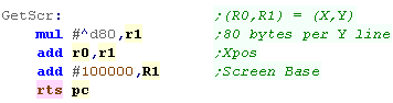 |
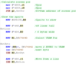
| We calculate the vram address in R1, then select it with port
176640 We then transfer bytes of our sprite to that vram address, two at a time, using ports 176642/3 We move down a line by adding decimal 80 to our screen pos |
 |
 |
Here we've used the RAP ports from the MAIN
cpu to set two bitpanes... we can't set the third from the MAIN
CPU, but we can from the SUB PP CPU... we'll learn about that next
time. We can also remap VRAM so it uses the part directly accessible from the MAIN CPU, that way we don't need to use the RAP ports to write to VRAM - We'll look at that another time too! |
Here's Chibiko!
| We're going to draw our Chibiko mascot onto the screen - the sprite is 48x48 pixels - 8 color |  |
| You can create sprites in the valid format with my AkuSprite Editor | 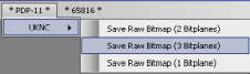 |
| The sprite is included in todays example. | 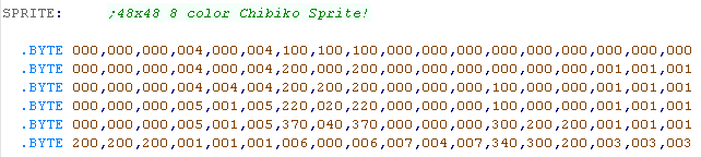 |
Sending
commands to the SUB CPU (PP)
| We need to transfer data to the SUB CPU, and tell it to act. It's ROM will take the command, transfer the program to it's memory and run it... in this case our sprite. We need a parameter command (PP.Params) - which includes a pointer to a 10 byte structure (PStruct) We'll tweak the parts of PS depending on what we need the SUB CPU to do. |
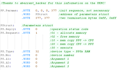 |
| We also have a 'Flag'... this is not part of the PP command, but we get the Sub CPU to alter it (Via the RAP) to tell the Main CPU the Sub CPU is done. |  |
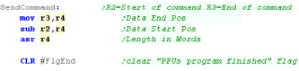
| Our SendCommand function takes
a command start and end address in R2/R3 We clear the flag that will be used when the program ends. |
 |
| First we use command 1 to get the SUB CPU to allocate memory | 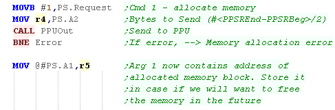 |
| We now need to transfer our program from the MAIN CPU to the SUB CPU... we use Command 20 to do this. | 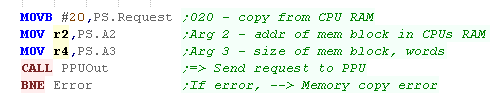 |
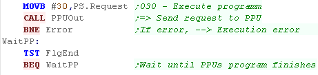
| Now we tell the SUB CPU to execute the
program with Command 30 We wait for the program to set the End flag - showing it's complete |
 |
| Once the program has finished we free the memory on the SUB Cpu with command 02 | 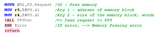 |
| PPUOUT transfers each PPU command to the SUB CPU | 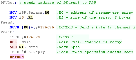 |
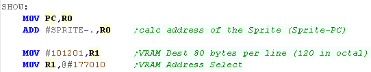
Drawing our sprite
| This program will run on the SUB CPU. We don't know where in RAM it will actually run, so we calculate the source sprite address compared to the current running code. We access VRAM via the RAP device, the VRAM data starts at octal address #100000+... Each screen line is 80 bytes (120 in octal) |
 |
| We select an address with RAP port 177010, we then write to the 3
bitplanes with 177012/4/5 After each byte, we INC 177010, we add 80 (80 in decimal / 120 in octal) to move down a line |
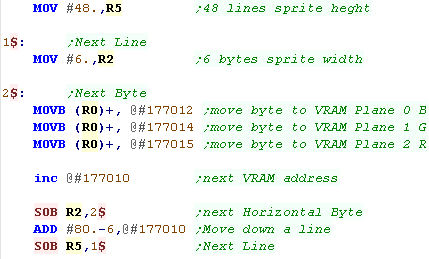 |
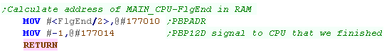
| After the Sprite had been transferred, we want to update FlgEnd to
tell the Main CPU the program has finished. We use the RAP device to do this - as RAM on the main CPU is split between 2 banks, we divide the address by 2, this gives the address the RAP needs to alter the address. |
 |
| These commands are quite a pain, but you can just use
them 'As is'... Pretty much all the samples you can find online use very similar code to what's been used here, so it's unlikely it's worth trying to 'optimize' them |
|
| We need to get the
SUB CPU (PP) to do the work of configuring the SLTAB, We're going
to use the same code as last time to transfer our program to the
SUB cpu! |
 |
UKNC SLTAB entries
309 (1..309) SLTAB records in total (lines 4..312 of SECAM's half-frame)
scanlines 1..19 are not visible due to the vertical blanking interval
scanlines 20..307 are visible (lines 23-310 of SECAM's half-frame)
scanlines 308..309 are not visible due to the vertical blanking interval
| F | E | D | C | B | A | 9 | 8 | 7 | 6 | 5 | 4 | 3 | 2 | 1 | 0 | ||
|
2 word record |
V | V | V | V | V | V | V | V | V | V | V | V | V | V | V | V | V=Vram Address |
| A | A | A | A | A | A | A | A | A | A | A | A | A | S | L | C |
C=Toggle Cursor on/off L=Length
of next record (2/4 words) S= 4-word selector (Options/Palette) / 2-word address bit 2 A=Address bits 3-15 |
| F | E | D | C | B | A | 9 | 8 | 7 | 6 | 5 | 4 | 3 | 2 | 1 | 0 | ||
| 4 word record Options |
- | C | C | C | C | C | C | C | G | G | G | T | Y | R | G | B | YRGB=Cursor color & Brightness / T=Type (Char/Graphic) / G=Graphic Cursor pos / C=Cursor pos |
| - | - | - | - | - | - | - | - | - | - | S | S | - | R | G | B | RGB= Line Brightness S=Scale (640/320/160/80) | |
| V | V | V | V | V | V | V | V | V | V | V | V | V | V | V | V | V=Vram Address | |
| A | A | A | A | A | A | A | A | A | A | A | A | A | S | L | C |
C=Toggle Cursor on/off L=Length
of next record (2/4 words) S= 4-word selector (Options/Palette) / 2-word address bit 2 A=Address bits 3-15 |
| F | E | D | C | B | A | 9 | 8 | 7 | 6 | 5 | 4 | 3 | 2 | 1 | 0 | ||
| 4 word record palette |
Y | R | G | B | Y | R | G | B | Y | R | G | B | Y | R | G | B | Palette bit combos %011 %010 %001 %001 |
| Y | R | G | B | Y | R | G | B | Y | R | G | B | Y | R | G | B | Palette bit combos %111 %110 %101 %100 | |
| V | V | V | V | V | V | V | V | V | V | V | V | V | V | V | V | V=Vram Address | |
| A | A | A | A | A | A | A | A | A | A | A | A | A | S | L | C |
C=Toggle Cursor on/off L=Length
of next record (2/4 words) S= 4-word selector (Options/Palette) / 2-word address bit 2 A=Address bits 3-15 |
Functions for defining the SLTAB
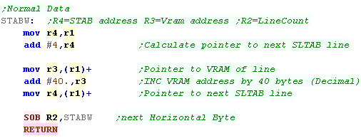
| We're going to create some functions which will define the 4 kinds
of line we'll use. The first is a normal 2 word line. This defines the VRAM address of the line in the first word, and a pointer to the next line, with settings of the line, in the second word. |
 |
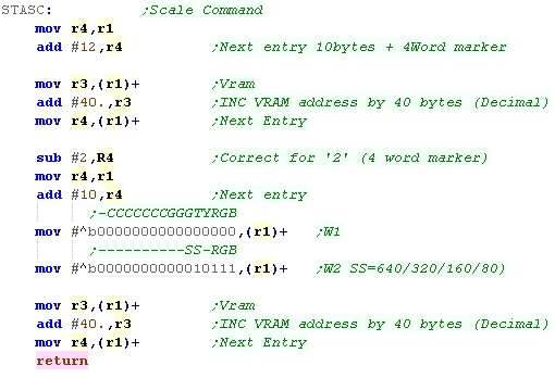
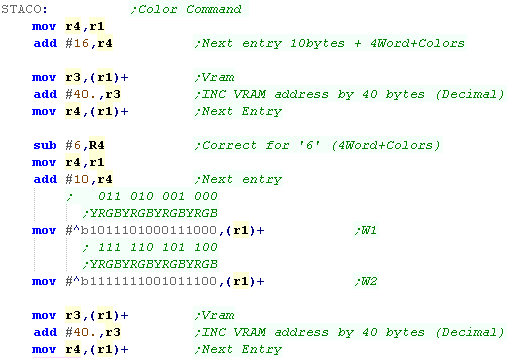
The second is a 'Scale command' (Options)... Here we're setting the Scale to 320 pixels... This command defines 2 lines, the first is a 'normal' 2 word line, but this defines the form of the second line... we tell the system the next line will have 4 words, and be an 'Options' line This is done by bits 4/5 of the second word. |
 |
| The third sets the colors (palette) This command defines 2 lines, the first is a 'normal' 2 word line, but this defines the form of the second line... we tell the system the next line will have 4 words, and be an 'colors' line Each cluster of 4 bits defines a color, in the format YRGB - where Y is brightness. We're remapping 'Blue' (bit pattern %001) to a dark cyan. (Bit pattern %0011) |
 |
| The fourth is a 'filler' line... this just shows as single VRAM line, and can be used for 'invisible area' | 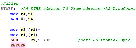 |
Defining our SLTAB
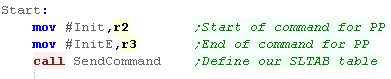
| We're going to need to get the SUB CPU (PP) to do our work, We send and execute this with the code we wrote last time! |
 |
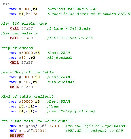
| We're going to actually define our table! The definition of our table will be at address 4000 in octal (in PP RAM)... we need to attach this to the start of the firmware SLTAB which appears at 270 (Vram address) and 272 (Pointer to next record) The first four lines we define set the scale and color. The next 32 are the top 'unused' area of the screen. Then we define 240 actual screen lines - we define these from 40000+... Note: This is within the CPU addressable ram area - so we won't need the RAP device! Finally we create a final entry that points to itself - this is the end of the screen. |
 |
Drawing to the screen
| We defined VRAM as address
40000... this makes the Red and Green channels accessible from the
MAIN CPU's normal memory addresses 100000+ It's not possible to address the blue channel in this way, but the SUB CPU can do so from address 40000+ |
 |
| Here's our Chibiko... no pesky RAP required! |
 |
Our Bitmap
font
| We're exporting our bitmap font with Akusprite Editor. The font is 1 bit per pixel however the bits are reversed horizontally... That is, the leftmost pixel is the right most bit, so our byte %76543210 colors pixels 01234567 |
 |
Printing
characters from the main CPU
| In our tutorials we use Char 255 terminated strings, Here we define our Hello World string |
 |
| We call this test routine from the main CPU |
 |
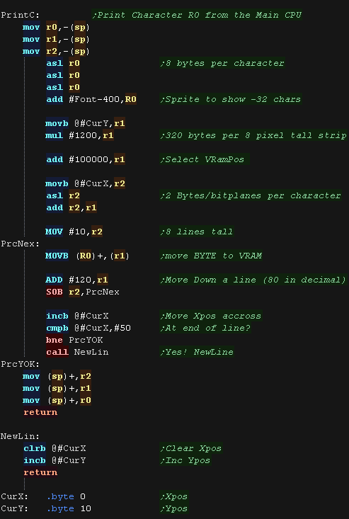
| We pass our character in R0. Each character in our font is 8
bytes, and our font has no character less than 32, so we shift R0 left 3 times to multiply by 8, and subtract 400 in octal to compensate for the missing characters. Our X,Y position is in 8x8 characters. Each horizontal character has 2 bitplanes (2 bytes), and each 'character strip' is 80 bytes * 8 lines=640 bytes (640 decimal = 1200 octal) Our VRAM Base is 100000 in octal so we calculate our VRAM destination with the following formula: 100000+(Ypos*1200)+(Xpos*2) .... note: All values in OCTAL! We transfer the font byte to the screen, and move down a line by adding 120 in octal. After drawing our character, we move the Xpos across one, and if we're at the end of the line we start a newline. |
 |
| Here is the result |
 |
|
This time we'll
print some characters from the SUB CPU, Please see the previous
examples for the code to transfer and run code from the SUB CPU! |
Printing
characters from the peripheral CPU
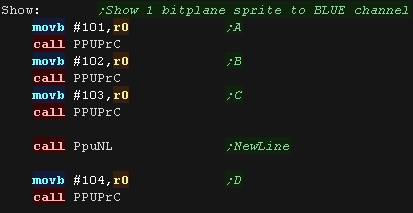
| Lets create a similar PrintChar routine which will run from the
'Sub' Peripheral CPU. Here we're printing a series of characters! |
 |
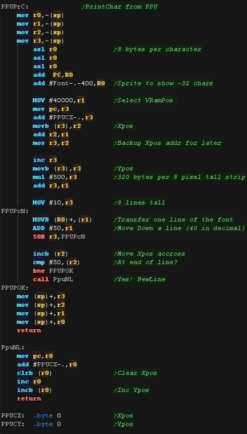
| Due to the screen configuration, the only difference is the memory
layout, our screen is just 1 bitplane from the Peripheral CPU We pass our character in R0. Each character in our font is 8 bytes, and our font has no character less than 32, so we shift R0 left 3 times to multiply by 8, and subtract 400 in octal to compensate for the missing characters. Our X,Y position is in 8x8 characters. Each horizontal character has 1 bitplanes (1 byte), and each 'character strip' is 40 bytes * 8 lines=320 bytes (320 decimal = 500 octal) Our VRAM Base is 40000 in octal so we calculate our VRAM destination with the following formula: 40000+(Ypos*500)+Xpos .... note: All values in OCTAL! We transfer the font byte to the screen, and move down a line by adding 50 in octal. After drawing our character, we move the Xpos across one, and if we're at the end of the line we start a newline. Note, As this code is 'relocated' to the Sub CPU Ram, all addresses are calculated relative to the program counter (specified by a full stop . ) |
 |
| Here is the result! |
 |
The Keyboard
hardware
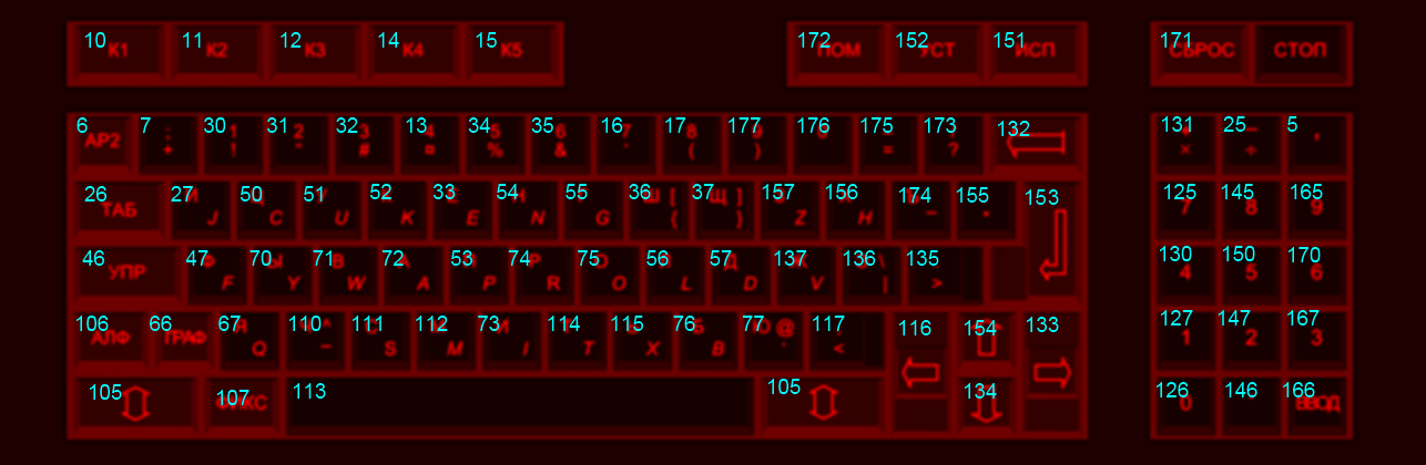
| Each key on the UKNC keyboard has a 'keycode' which uniquely
identifies it. This is passed in entirely when a key is pressed down, or partially when a key is released. |
 |
|||||||||||||||||||||||||||
| We can read the keyboard only from the PPU, The best way is by
writing our own Keyboard interrupt handler, and copying it's address
to memory address #300 in octal... This will cause it to execute
each time a key is pressed or released. We can then read port 177702 to get the details of the key that was pressed. Bit 7 will be zero if a key was pressed down... Bits 0-6 will give the full keycode of the key pressed down. Bit 7 will be 1 if a key was released up... Bits 0-3 will give the partial keycode of the key released - this means it is not possible to 100% uniquely identify the key that was released. |
|
Reading from
the keyboard
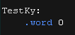
| We're going to set up a
keyboard handler on the SUB CPU, however it will write its results
to the main CPU's ram via the RAP device - allowing us to use it's
results easily! We'll transfer two bytes - the first is the raw data from the keyboard (For testing), and a 1 byte representation of the directions, and possible fire buttons (for our games) |
 |
| We'll transfer the program to the SUB CPU in the same way as
before, The first program will just have one task... Set up
the interrupt! To do this, we just need to put the address of our interrupt handler in address 300 (in octal) of the memory of the SUB CPU (peripheral cpu - not main CPU memory!) |
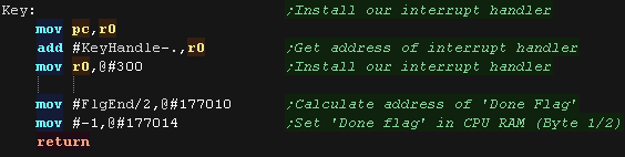 |
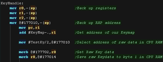
| We're using the RAP device to write to MAIN CPU RAM from the SUB
CPU The main cpu uses 2 banks for alternating bytes, so we halve the destination address, and write this to port 177010 We then read in the data from the keyboard hardware from port 177702 We send this raw data via the RAP device to the first byte with port 177014 |
 |
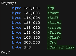
| We're going to process this data, and convert it into a simulated
'Joystick' We'll return a single byte, where each direction will be a bit in the format %P321RLDU - with keys Up Down Left Right, Space Enter and Shift for fire, and Escape for a pause button. We use a Keymap to do this, which uses pairs of bytes, the first is the Keycode, the second is the bitmask. |
 |
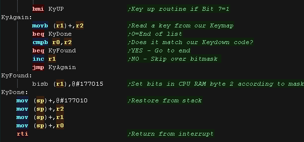
| if bit 7 of our read in byte is a zero, a key has been pressed
down. We scan through the KeyMap until we find a match (or we get to the zero at the end of the list) If we find a match We set the bit from the second byte with BIS We set the second byte via the RAP device with port 177015 |
 |
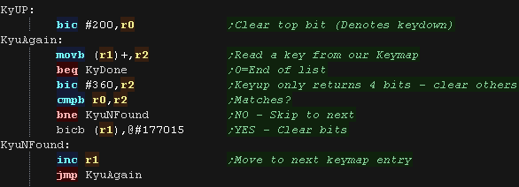
| if bit 7 is one then a key is released. Once again we scan the keymap, BUT only 4 bits of the keycode are returned when a key is released, so we use 'bic #360,r2' to ignore the other 3 bits of the tested keycode. For any matches, We clear the bits with BIC, because there are only 4 bits returned by the hardware, multiple keys could match. |
 |
| Space and Enter
aren't really the best fire buttons as there's some 'keyclash'
with the other keys! Still it's only a test, and you can easily choose your own keys just by changing the 'Keymap' to something better. |
 |
Introducing ChibiSound!
| In these tutorials we're going to
create an 'amazing' new sound API to rival Directsound!!!... well at
least the functionality won't break like Directsound 3D did! Well, no it won't... what it will do is take a byte value from 0-255, and make a sound of selectable pitch, with noise or half volume in a similar way on all our systems! This was created for Grime Z80, and allows common sound code to give similar effects on all the systems! All we do is load the accumulator with a value, and call ChibiSound! Of course, this won't be enough to make musicbut it will give us some simple SFX, and make it easy to compare doing simple tasks on our various systems! |
|
|
Because the
UKNC only has an 'off' and 'on' state for sound, we won't be able
to do a loud and quiet volume. We will however be able to do noise, by randomizing the times we turn the sound on and off. |
Chibisound on the Main CPU!
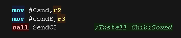
| The Chibisound driver needs to run on the SUB PPU. We'll have to transfer and leave it running to get sound. |
 |
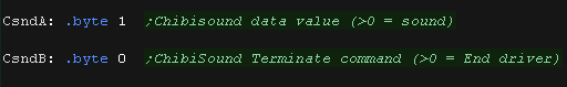
| We'll control Chibisound via two bytes in RAM on the main CPU. The first (CsndA) is the sound byte we want ChibiSound to play (in the format specified above) The second (CsndB) is left as 0 until we want to stop ChibiSound - If we want the PPU to resume other task we'll need to terminate Chibisound to do this. |
 |
Chibisound driver on the Sub CPU (PPU)!
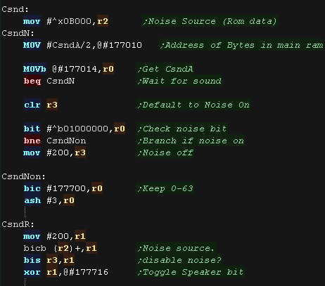
| Chibisound needs a 'random' source of data for the noise effect,
we use part of the ROM for this, the 0xB000-0xD000 range. We now test 'CsndA' - if it's Zero we should stay silent... anything else is a tone we need to make! We set bit 7 of R3 to one if the noise is disabled, and get the pitch of the sound we should make in R0. We then flip the bit 7 of port 177700 (in octal) - using the noise if needed, repeatedly flipping the bit makes the sound wave. |
 |
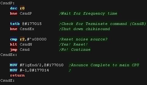
| We need to pause a while and flip the bit again - the amount of
time we wait depends on the pitch we want (longer = lower pitch) we then check if we've been told to shut down chibisound with CsndB, we also check if R2 has reached the end of the range of data we use for noise, we then repeat the whole procedure to continue making the sound. |
 |
| View Options |
| Default Dark |
| Simple (Hide this menu) |
| Print Mode (white background) |
| Top Menu |
| ***Main Menu*** |
| Youtube channel |
| Patreon |
| Introduction to Assembly (Basics for absolute beginners) |
| Amazon Affiliate Link |
| AkuSprite Editor |
| ChibiTracker |
| Dec/Bin/Hex/Oct/Ascii Table |
| Alt Tech |
| Archive.org |
| Bitchute |
| Odysee |
| Rumble |
| DailyMotion |
| Please note: I wlll upload more content to these alt platforms based on the views they bring in |
| 68000 Content |
| ***68000 Tutorial List*** |
Learn 68000 Assembly  |
| Hello World Series |
| Platform Specific Series |
| Simple Samples |
| Grime 68000 |
| 68000 Downloads |
| 68000 Cheatsheet |
| Sources.7z |
| DevTools kit |
| 68000 Platforms |
| Amiga 500 |
| Atari ST |
| Neo Geo |
| Sega Genesis / Mega Drive |
| Sinclair QL |
| X68000 (Sharp x68k) |
| 8086 Content |
| Learn 8086 Assembly |
| Platform Specific Series |
| Hello World Series |
| Simple Samples |
| 8086 Downloads |
| 8086 Cheatsheet |
| Sources.7z |
| DevTools kit |
| 8086 Platforms |
| Wonderswan |
| MsDos |
| ARM Content |
| Learn ARM Assembly |
| Learn ARM Thumb Assembly |
| Platform Specific Series |
| Hello World |
| Simple Samples |
| ARM Downloads |
| ARM Cheatsheet |
| Sources.7z |
| DevTools kit |
| ARM Platforms |
| Gameboy Advance |
| Nintendo DS |
| Risc Os |
| Risc-V Content |
| Learn Risc-V Assembly |
| Risc-V Downloads |
| Risc-V Cheatsheet |
| Sources.7z |
| DevTools kit |
| MIPS Content |
| Learn Risc-V Assembly |
| Platform Specific Series |
| Hello World |
| Simple Samples |
| MIPS Downloads |
| MIPS Cheatsheet |
| Sources.7z |
| DevTools kit |
| MIPS Platforms |
| Playstation |
| N64 |
| PDP-11 Content |
| Learn PDP-11 Assembly |
| Platform Specific Series |
| Simple Samples |
| PDP-11 Downloads |
| PDP-11 Cheatsheet |
| Sources.7z |
| DevTools kit |
| PDP-11 Platforms |
| PDP-11 |
| UKNC |
| TMS9900 Content |
| Learn TMS9900 Assembly |
| Platform Specific Series |
| Hello World |
| TMS9900 Downloads |
| TMS9900 Cheatsheet |
| Sources.7z |
| DevTools kit |
| TMS9900 Platforms |
| Ti 99 |
| 6809 Content |
| Learn 6809 Assembly |
| Learn 6309 Assembly |
| Platform Specific Series |
| Hello World Series |
| Simple Samples |
| 6809 Downloads |
| 6809/6309 Cheatsheet |
| Sources.7z |
| DevTools kit |
| 6809 Platforms |
| Dragon 32/Tandy Coco |
| Fujitsu FM7 |
| TRS-80 Coco 3 |
| Vectrex |
| 65816 Content |
| Learn 65816 Assembly |
| Hello World |
| Simple Samples |
| 65816 Downloads |
| 65816 Cheatsheet |
| Sources.7z |
| DevTools kit |
| 65816 Platforms |
| SNES |
| eZ80 Content |
| Learn eZ80 Assembly |
| Platform Specific Series |
| eZ80 Downloads |
| eZ80 Cheatsheet |
| Sources.7z |
| DevTools kit |
| eZ80 Platforms |
| Ti84 PCE |
| IBM370 Content |
| Learn IBM370 Assembly |
| Simple Samples |
| IBM370 Downloads |
| IBM370 Cheatsheet |
| Sources.7z |
| DevTools kit |
| Super-H Content |
| Learn SH2 Assembly |
| Hello World Series |
| Simple Samples |
| SH2 Downloads |
| SH2 Cheatsheet |
| Sources.7z |
| DevTools kit |
| SH2 Platforms |
| 32x |
| Saturn |
| PowerPC Content |
| Learn PowerPC Assembly |
| Hello World Series |
| Simple Samples |
| PowerPC Downloads |
| PowerPC Cheatsheet |
| Sources.7z |
| DevTools kit |
| PowerPC Platforms |
| Gamecube |
| Work in Progress |
| ChibiAndroids |
| Misc bits |
| Ruby programming |
Buy my Assembly programming book
on Amazon in Print or Kindle!


Available worldwide!
Search 'ChibiAkumas' on
your local Amazon website!
Click here for more info!


Buy my Assembly programming book
on Amazon in Print or Kindle!
Available worldwide!
Search 'ChibiAkumas' on
your local Amazon website!
Click here for more info!
Buy my Assembly programming book
on Amazon in Print or Kindle!
Available worldwide!
Search 'ChibiAkumas' on
your local Amazon website!
Click here for more info!
Buy my Assembly programming book
on Amazon in Print or Kindle!
Available worldwide!
Search 'ChibiAkumas' on
your local Amazon website!
Click here for more info!
Buy my Assembly programming book
on Amazon in Print or Kindle!
Available worldwide!
Search 'ChibiAkumas' on
your local Amazon website!
Click here for more info!
Buy my Assembly programming book
on Amazon in Print or Kindle!
Available worldwide!
Search 'ChibiAkumas' on
your local Amazon website!
Click here for more info!
Buy my Assembly programming book
on Amazon in Print or Kindle!
Available worldwide!
Search 'ChibiAkumas' on
your local Amazon website!
Click here for more info!
Buy my Assembly programming book
on Amazon in Print or Kindle!
Available worldwide!
Search 'ChibiAkumas' on
your local Amazon website!
Click here for more info!
Buy my Assembly programming book
on Amazon in Print or Kindle!
Available worldwide!
Search 'ChibiAkumas' on
your local Amazon website!
Click here for more info!
Buy my Assembly programming book
on Amazon in Print or Kindle!
Available worldwide!
Search 'ChibiAkumas' on
your local Amazon website!
Click here for more info!
Buy my Assembly programming book
on Amazon in Print or Kindle!
Available worldwide!
Search 'ChibiAkumas' on
your local Amazon website!
Click here for more info!