

Absolute beginners series
The Beginners series is designed as an introduction to the concepts of Assembly and retro programming, it does not aim to teach a particular assembly language (I have other tutorials for that!).
This series is designed to give you a good 'foundation' of background knowledge before you start learning Assembly, or as a supplement if you're looking at assembly programming and are finding it tough (Which is completely understandable)
 |
Don't like to read? you can learn while you
watch and listen instead! Every Lesson in this series has a matching YOUTUBE video... with commentary and practical examples Visit the authors Youtube channel, or Click the icons to the right when you see them to watch the Lessons video! |
 |

What is Assembly Language?
Assembly Language is an early very Low level language. Its commands are more readable than the 'Machine Code' the CPU actually runs, but is still reasonably human readable to help the programmer.
Rather than a 'High Level Language' like C++ which does a lot to help us, Assembly converts straight to the machine code that the CPU runs.
This makes it faster than High level languages, but it means the programmer has do do more of the work of writing the program.
That sounds difficult! Why should I use Assembly Language then?
Well, if you're writing a program for your job � you almost certainly should use something else! But if you're looking to learn programming for a hobby, or you're trying to make an impressive game on an old system with limited hardware, then assembly is worth taking a look at.
I would say It's like taking a train compared to running a marathon. Do you want to get somewhere quickly, or do you want a challenge?
Assembly programming will teach you new skills, and let you take a different look at the old computers you've used for a long time.
Assembly language is harder to get started than C++, and you'll
almost certainly need to research the hardware you're programming, and
plan your project well. But the extra effort will be worth it, as the
result will be a program that you made 100% by yourself!
Unlike with High level languages, there will be no Unreal engine doing
all the game engine, no SDL handling the sound and no OpenGL doing the
graphics. You'll have done it all yourself and know how it all works!
What can Assembly Language Do?
Anything you want! Because it's so low level, other languages, like C++, Forth and Basic, all end up as Assembly. So in theory anything those languages can do, you can do in Assembly, if you have the persistence!
If you're just starting out, you should probably be aiming to make simple games like Pong, Space Invaders or something of that style. While it's possible to write your own Window based Operating System in Assembly, you'd probably be better off aiming for something more realistic to start unless you're very confident.
How do I learn Assembly Language?
The only way to learn Assembly is through a combination of study and practice. You'll need to understand the instruction set of the CPU you're interested in, the hardware of the platform you're wanting to develop for and probably the OS of the system as well.
This can only be achieved by research and study and all the documentation you'll need is out there free on the web. But you'll probably find it impossible to understand without trying it for yourself, so writing little test programs to put what you read into practice will help.
Enough talk! Let's start learning Assembly!Overview of the retro computer system
| Every computer
is different, but the general structure of the classic 8 and
16 bits tends to follow some common patterns. Of course the part our commands will run on is the 'CPU', but the CPU can't do anything on its own. To call the CPU the 'Brain' of the computer would be an overstatement, as it's a 'brain' that can't remember anything for very long, so it needs the Memory to store things for it. Computer systems will have a combination of RAM (Random Access Memory - for storing data) and ROM (Read Only Memory - for the operating system). Some systems will have a Keyboard, but every system will have at least some kind of input like a gamepad. These don't connect directly to the CPU. There will be some kind of 'Input/Output chip' we'll have to 'ask' for the data. Most systems will have some kind of sound. This will usually be some kind of chip we can tell what sound to make, but some have a 'beeper', where we basically have to make the shape of the sound with the CPU. Depending on the system, there may be a tape or disk device we can read data from. The reading or writing procedure is too complex to do directly, so we probably want to ask the operating system to do the work for us. Finally we have the graphics, because we'll want to 'see' some results! How the graphics work will vary from system to system. Some systems have separate graphics memory and others do not. All will have some kind of 'graphics chips' which we can tell to do things, like change the colors on screen, or change the screen resolution.
|
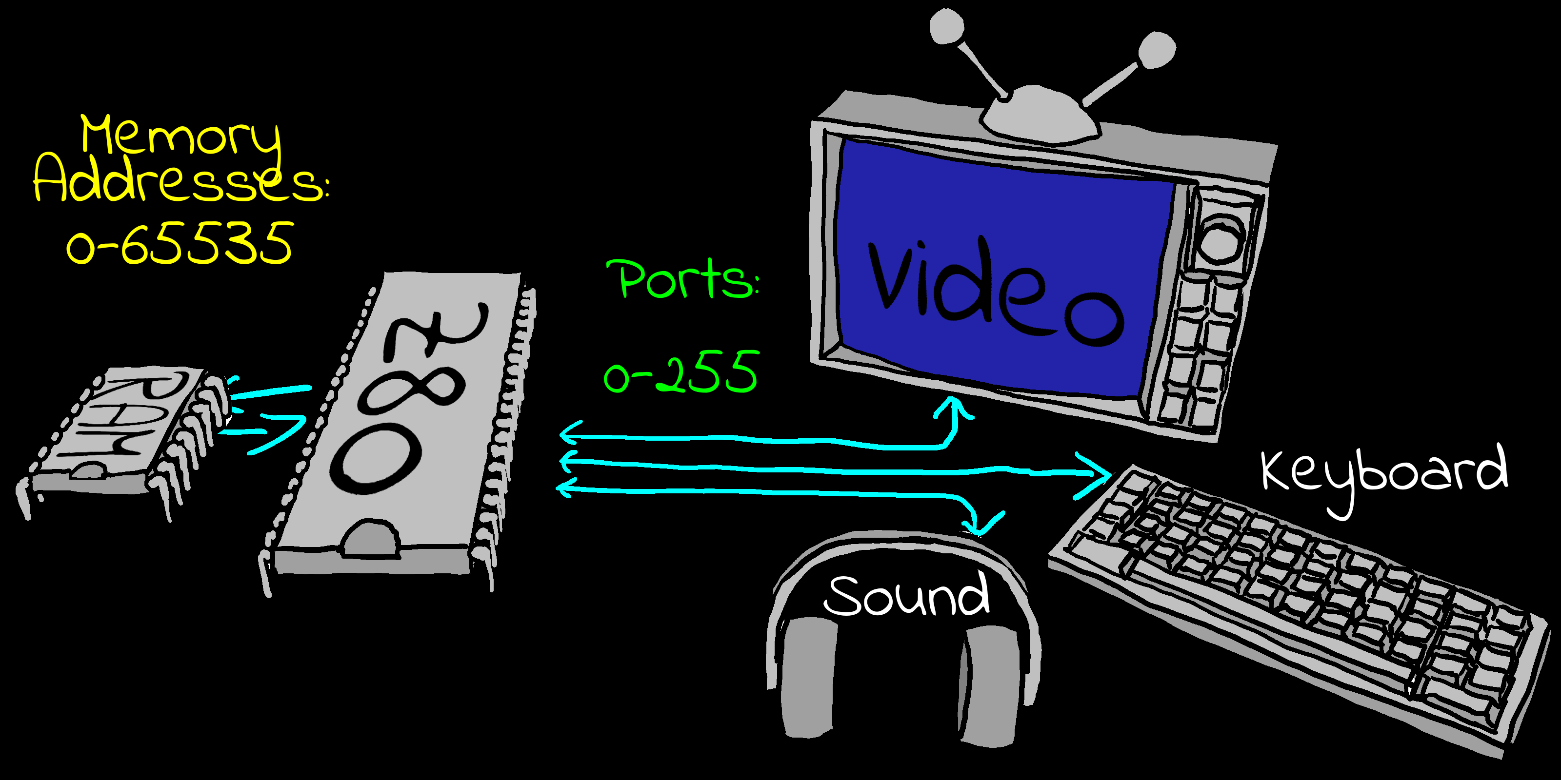
Let's take a
look at an 'imaginary system' its parts and how they connect
-> 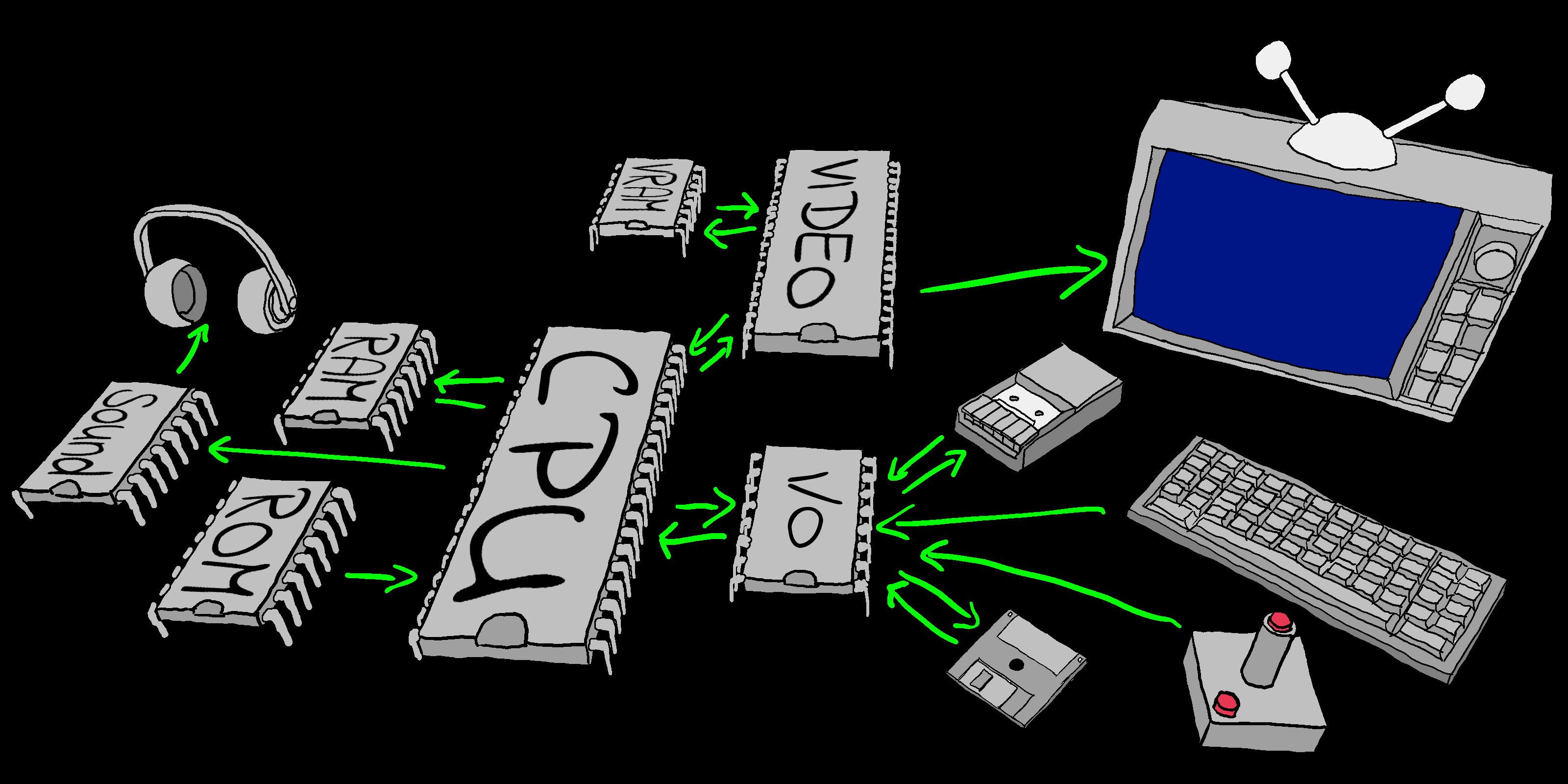 The layout of an imaginary 'typical' system. |
CPU Terminology
Let's start by looking at some common terms you'll come across in Assembly. We'll discuss what they mean to you as a programmer.
CPU
| The CPU is the 'Calculator' of our machine,
it reads in numbers and commands, and calculates the results.
Commands and parameters will be usually read in from memory, the results will be stored back to memory. Sometimes the source or destination may be a 'device' like a joystick or speaker. How connection to such devices works depends on the CPU and the hardware. |
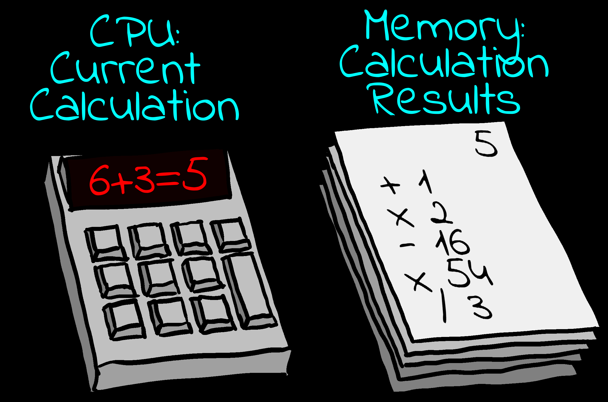 The CPU calculates the current calculation. The memory stores the results and future calculations. |
Memory
| Memory is our main storage for our program
code, graphics data and values such as our score, the XY
position of our player and everything else!
Each byte of memory has a numeric 'address'. Think of it like a huge set of lockers, each has a number and each 'locker' contains a byte of data which we can read or write. The 'Address bus' is a set of wires that connects the CPU to the Memory. Though its calculations are 8 bit, a Z80 system has a 16 bit 'address bus' so it can address 64K of memory (0-65535), though this can be extended with 'Bank Switching'. Bank switching is where part of the memory map will 'switch' between different areas of memory. On the 128K CPC, the range &4000-&7FFF can switch between one of the 8 available 16k banks, giving our program access to more memory within the 64K address space. |
 Memory is like a bank of numbered 'lockers' that can each store 1 byte messages. |
RAM and ROM!
| There are two kinds of memory:
RAM is 'Random Access Memory', this just means it can be
read or written. Systems like the CPC and Spectrum have lots of RAM, and a bit of ROM for things like screen and tape routines. On Systems like the Sega Master System and NeoGeo, the Cartridge which stores our program is read only ROM, and the game system has a small amount of writeable RAM for our variables and other stuff.
|
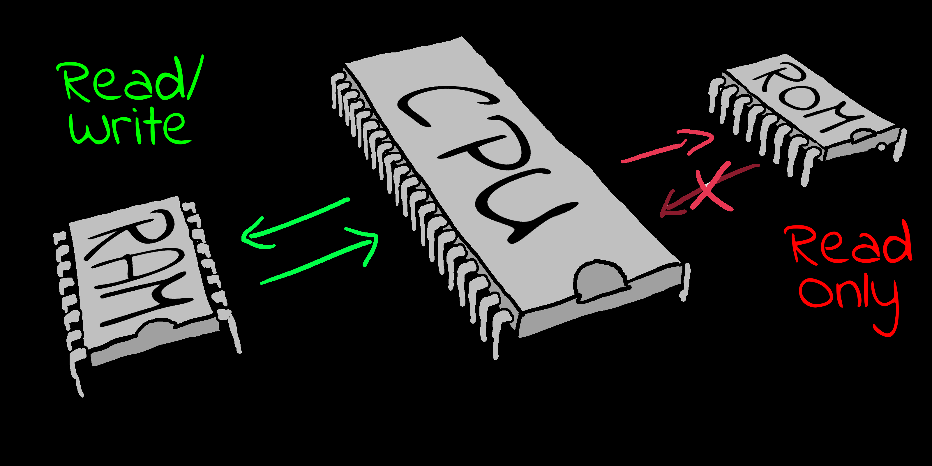 RAM can be read or written, ROM can only be read. |
Registers
| The CPU has a very small amount of built in
memory to remember parameters for the calculations, usually just
a few bytes (depending on the system).
This is 'short term storage'. It's much faster than RAM because it's inside the CPU but we have very few registers, so we have to use the slower normal memory a lot. Systems like the 6502 have just 3 main registers, and systems like the Z80 have over a dozen. That's not to say the 6502 is 'worse', it just works differently. Though the 6502 has fewer registers it can access memory faster instead.
|
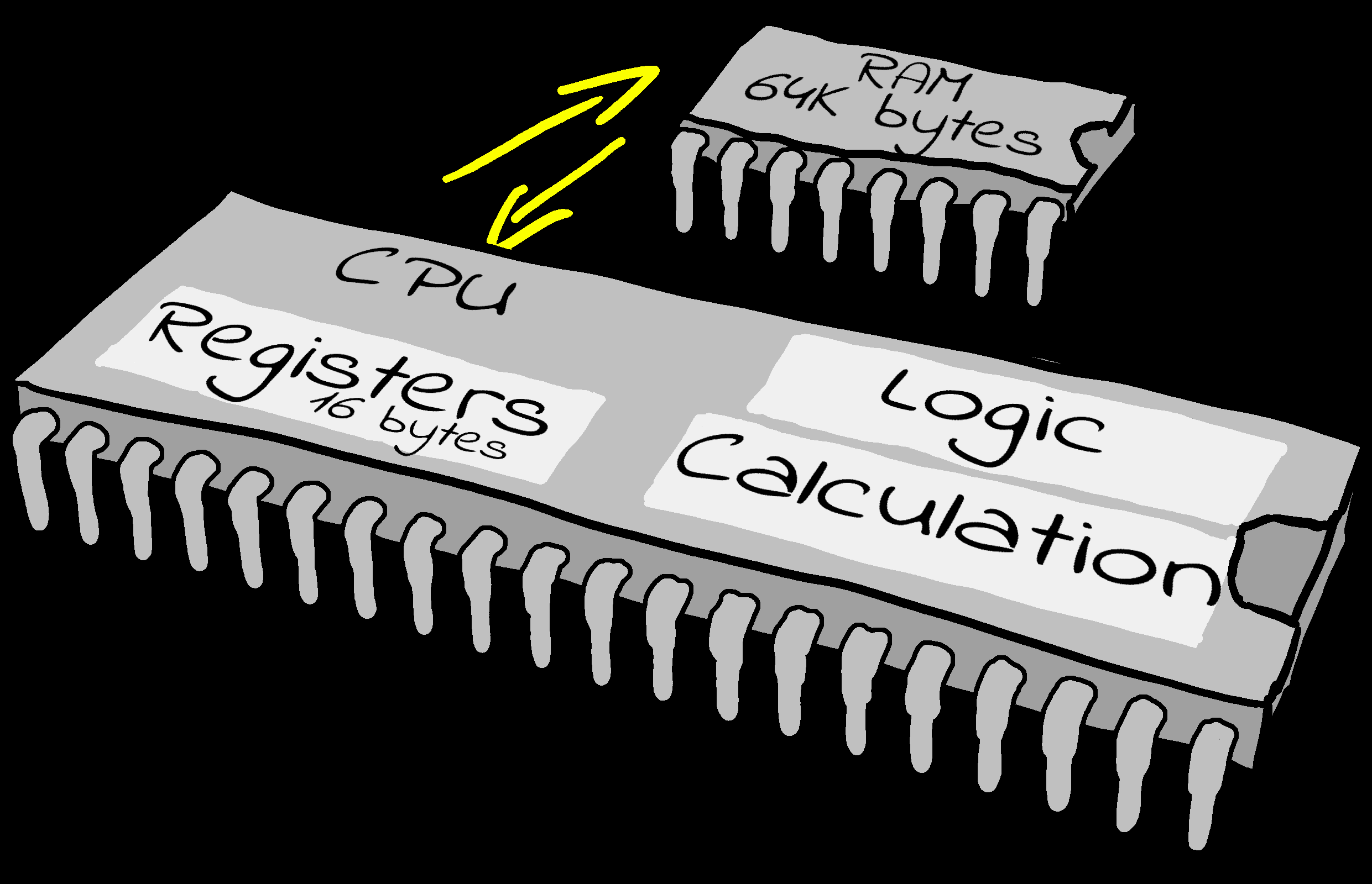 Registers are 'short term memory', just a few bytes are available. RAM is 'Long term memory' many Kilobytes or even Megabytes will be available. |
 |
There's lots
more technical stuff to learn about the CPU, but we'll look at
that next time! If you're feeling super confident, you can jump over to the Assembly tutorials of whatever CPU interests you... otherwise stick around, and next time we'll look at more of the CPU technical details. |

Accumulator Register (A)
The Accumulator is the main register for calculations. It can only store one calculation result at a time, you can think of it like the screen on your calculator. The register is referenced by the letter 'A'.
Old CPU's, like the 6502 and Z80, had a single Accumulator.
More modern ones, like the ARM/68000, don't work like that. On the
68000 or ARM any register of the half dozen or so can do the
calculations, so there's no single 'Accumulator'.
Program Counter Register (PC) / Instruction Pointer (IP)
| The code of our program will be somewhere in
memory. The Program Counter points to the address of the line of
code the CPU is going to process next. It's like following a 'to do list' and pointing your finger at each line as you move through the list. Without the program counter the CPU wouldn't know what bytes to read in next to work on. |
 The Program Counter points to the current 'job' being worked on. |
Flags Register / Condition Codes
| Whenever we do a calculation, the flag
register will store the 'answers' to some questions we may ask.
For Example: Z Flag Was the result Zero? |
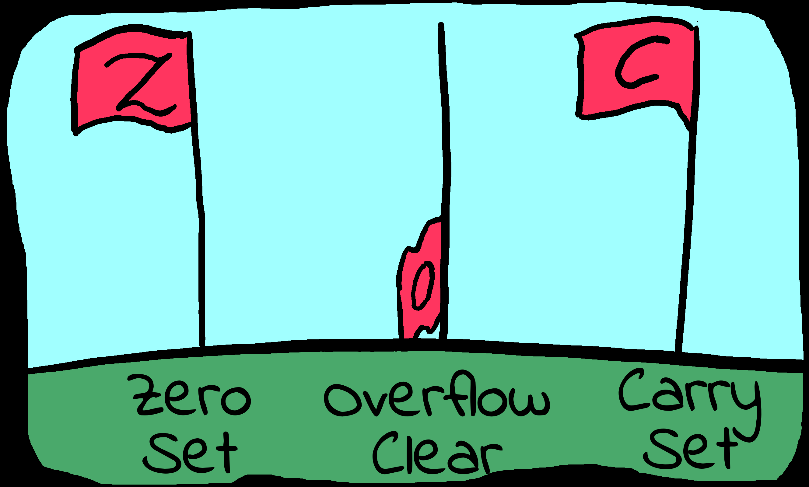 Flags can be set (1) or Clear (0). |
Flags are called Condition Codes on some CPUs and are held in the 'Condition Code Register' (CCR).
Not all commands set the flags, you will need to check the instruction documentation to know if they do. Also some commands may leave a flag in an 'undetermined state', meaning it's changed but not predictable or useful.
We can take advantage of unchanged flags. On the Z80, "DEC A" changes the z flag, but "LD" does not. We can take advantage of this in our program code.
For Example: Consider the code "DEC A LD A,10 jr z,AccZero". This takes advantage of the fact "LD A,#" does not change the z flag. If DEC A sets the zero flag, the jump will occur, and the Accumulator will equal 10 after the jump.
In the instruction references of this book, the 'Flags Affected' section will show a minus '-' when an instruction leaves a flag unchanged, an uppercase letter when a flag is correctly updated (for example 'C'), and a lowercase letter when a flag is changed to an undetermined state (for example 'c').
The Carry Flag
| The Carry flag is quite important on 8 bit
systems, as it allows us to combine registers together to store
larger values than the resister can contain. It works in a
similar way to 'carrying' if you do long addition or
multiplication on paper.
For Example: On the 8 bit 6502, suppose there is a 16 bit pair in $01,$02 and we want to add the pair at $03,$04. We do this by adding the two low bytes together ($01 and $03) then adding with the carry the high bytes ($02,$04). Because the 6502 is a Little Endian CPU, $01 and $03 are the Low byte and $02 and $04 are the High byte. If the first addition goes over 255, the carry will be set to 1, and this will be added to the high byte. |
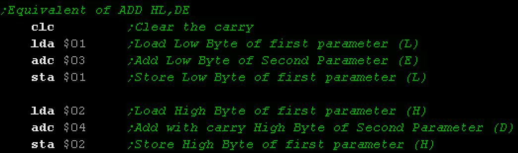 The 6502 uses 8 bit registers, but we can use the 'Carry flag' to transfer the 'carry' during addition between two or more bytes to allow us to support 16 or more bit values. |
I/O Ports � Input/Output Ports
| There will be times we need to transfer data
to a device other than RAM memory. For Example: We may want to read the status of the Joysticks, or make a sound, and we use I/O ports to do this. On the Z80 and 8086 system we have special commands to do
this. Things can be very different depending on the computer. On the Z80 based CPC the VRAM (Video Ram) is part of the normal memory, but on the Z80 based MSX it is separate and we have to use I/O ports to access it.
|
 The RAM addresses and I/O ports are separate. |
Stack
| The stack is a temporary store for data. We
don't have very many registers, and there will be times (like in
a subroutine) where we need to put all the current data to one
side and do another job for a while, then bring all the old data
back. This is what the Stack is for. When we have some data we need later, but need to do something else first, we put it on the stack. Later we'll take it off and use it again. You can think of the stack like your office in-tray. We can put jobs in our 'in tray' when we want to do them later, and pull them out when we want to work on them again. We can put as many items into our in-tray as we want, but we have to take them off the top of the in-tray, not from the middle. The same is true of the stack. We can put many items onto the stack, but they always go on top of the last one, and we have to remove them in the reverse order, taking out first the last item put in. This is called a Last In First Out stack. This means we put items 1,2,3 onto the stack and we'll take them back in order 3,2,1. The current position in the stack (the top of our in-tray) is marked by the Stack Pointer (SP). Technically speaking, the stack actually goes DOWN in memory. If the Stack Pointer starts at $C000 and we put (PUSH) two bytes onto the stack, the Stack Pointer will point to $BFFE. When we take the bytes off (PULL/POP) the Stack Pointer will point to $C000. The Stack Pointer always points to the first empty byte of the stack.
|
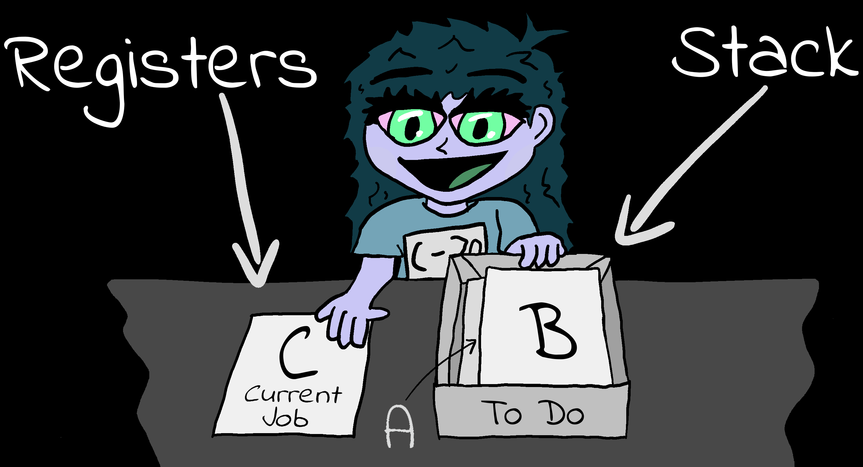 Items we'll look at later go on the top of the stack. |
Interrupts
| Interrupts are exactly what they sound like!
Sometimes a device, Like a disk or mouse, will want to send some
data to be processed RIGHT NOW!
The CPU will have to stop whatever it was doing and deal with the data. The current running program will be interrupted, and a 'sub program' will run (usually in system ROM) to deal with the interrupt. When the interrupt is done, the original running program will resume as if nothing happened. On 8 bit systems we can turn interrupts off in many cases. On most systems we can create our own interrupt handlers to do clever things, like make the screen wobble by moving things as the screen is drawing. There are two kinds of interrupt: |
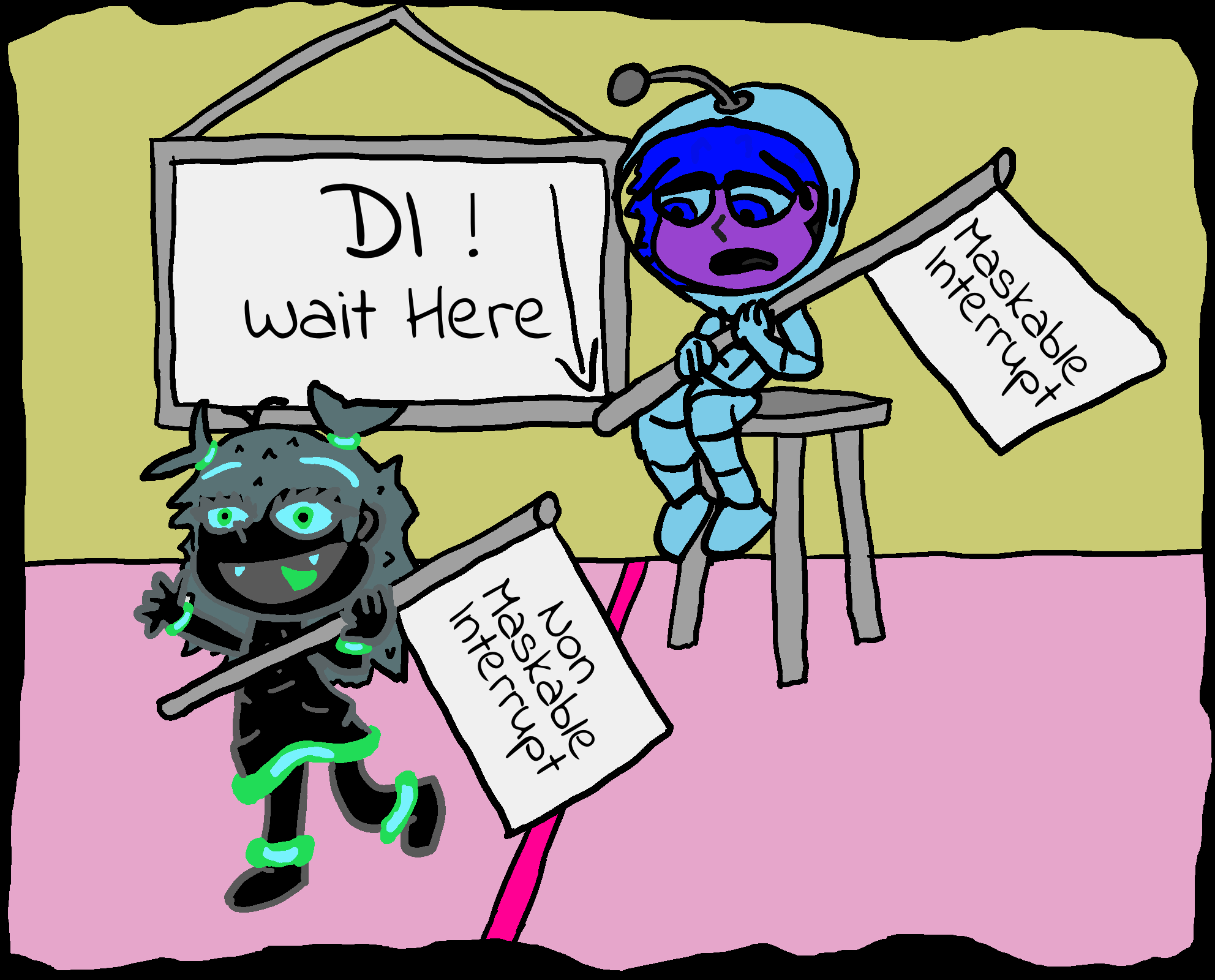 NMI can't be stopped by Disabled Interrupts (DI). |
Endian, Big Endian and Little Endian
| Even on an 8 bit system there will be times
when we need to store a 16 bit or more number, and whether our
CPU is 8,16 or 32 bits, each memory address in RAM will only
store 1 byte, so we'll need to split larger numbers up into
individual bytes for storage.
Let's imagine we have 32 bits to store, this will take four bytes of RAM. But in what order should these four bytes be stored? It may be surprising to hear that there are two options. 'Big Endian' stores the highest byte first and the lowest
byte last. It's not really up to us what 'Endian' to use, as our CPU
will have its 'Endian' built into its memory addressing. |
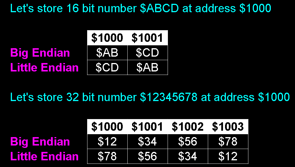 Big and Little Endian compared. |
The ISO9660 CD format uses a format known as �Both Endian�, where a value is stored as Little Endian, followed by Big Endian. This means a 16 bit value takes 32 bits of storage space, and is intended to allow easy portability with systems using either type of CPU.
| Fun Fact: The terms 'Big Endian' and 'Little Endian' actually come from the fictional nation of "Lilliput" in "Gulliver's Travels" which split in two factions over from which 'end' an egg should be eaten! Take a look at this link for more details: |  |
RST / Traps
RST (ReSeT) commands on the Z80, Traps on the 68000, and Interrupts on the 8086 and ARM are special 'commands' which cause a special subroutine to run, What these do depends on the machine.These can sometimes be caused by hardware events, but Traps are also used for debugging, error handling and operating system calls.
On many Z80 systems RST7 occurs when the screen starts drawing.
On the 68000 Traps are also used for errors (like Divide by zero) and even help with debugging! There is a special "Step" trap which will occur after each command so we can check what's happening.
Interrupts on systems like DOS using the 'INT' command on the 8086, and Software Interrupts on RiscOS using the 'SWI' command on the ARM are used to perform system actions, like changing screen mode.
Privilege Modes
In the 8 bit days, CPUs were pretty basic, and user applications and the operating system both had the same power and abilities, but the later CPUs like the 68000 had 'Privilege' modes.
On 16 and 32 bit CPUs Privilege would often be split into 'User' and 'Supervisor'
User mode would be for the running program.
Supervisor would be for the Interrupts and other system tasks. There are often 'alternate' registers and commands available only to supervisor mode. It's quite probable there will be many more levels of privilege on more modern CPUs.
Zero Page / Direct Page
| On 8 bit CPUs with few registers, like the
6502 or 6809, the lack of registers is compensated for by the
'Zero page'.
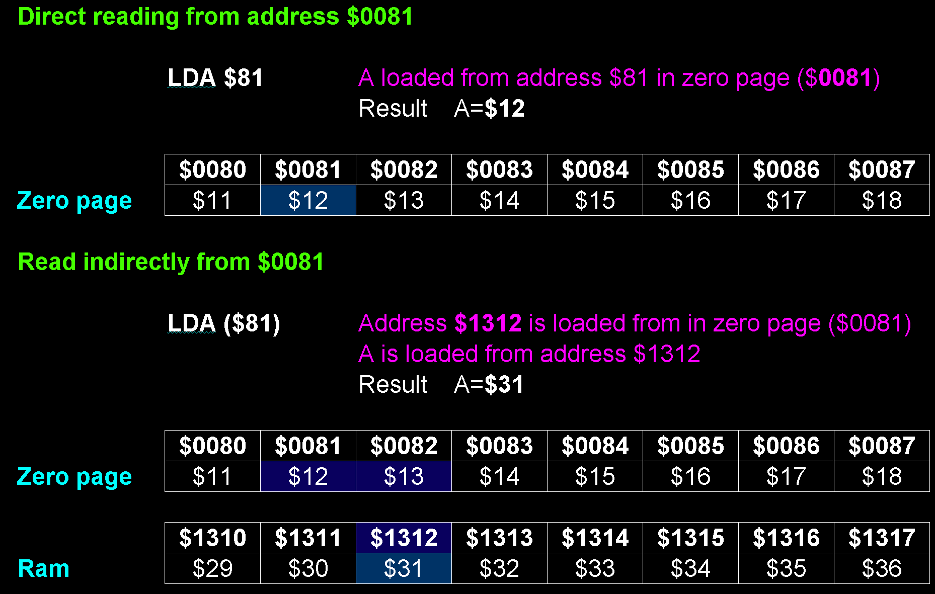
This uses a block of 256 bytes for quick storage of values. Reading and writing to this range is faster than regular memory. The Zero Page uses the memory range $0000-$00FF. Rather than specifying a full address we just specify a single byte, so a command like "LDA $66" will load A from address $0066. The top byte is always Zero, hence the name! On later systems like, the 65816, the top byte of the resulting address was configured by a one byte 'Direct Page Register', so the 'Zero Page' is referred to as the 'Direct Page' on these systems, though its function is basically the same. |
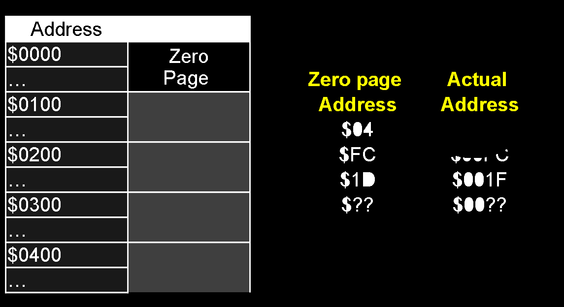 The Zero Page uses the first 256 bytes of RAM. Zero page addresses are specified with a single byte. |
Segment Registers / Bank Registers
| These only exist in CPUs with a 20/24 bit address bus,
like the eZ80, 65816 or 8086. These have a 24 bit address bus,
but keep their original 16 bit registers. This leaves a
'shortfall' of 8 bits for address calculation.
The solution to
this is often an 8 bit register defining the top byte. This
register is known as a 'Segment Register' on the 8086, or
'Bank register' on the 65816 and 'Mbase' on the eZ80. Segment Registers allow extra memory to be used, while retaining compatibility with the old programming methods. However they are more limited than a true 24 bit addressing system like the 68000 CPU. |
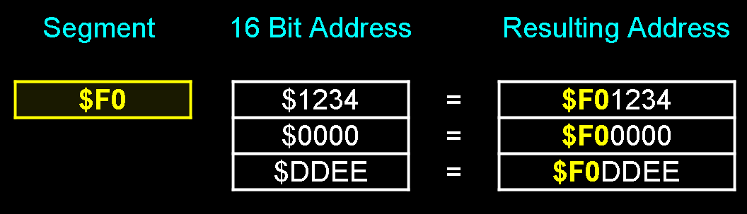 An 8 bit segment register is added to the top of a specified 16 bit address to make a 24 bit one. |
Segments also relate to Logical and
Physical addresses. On a CPU like the 65816, Our 64K program may
only be able to see a 16 bit, 64K of memory with memory addresses
$0000-$FFFF. In this case this would be referred to as the programs
'Logical Address'.
However, that range will be part of a much larger range of the actual resources the system offers. For Example: The true 24 bit address of that memory could be $7F0000-$7FFFFF. This 'True Address' is the 'Physical Address'.
Base Pointer + Offset
| There are many times
where the source or destination address for a command will
be calculated from two separate
values.
The terminology may vary depending on CPU, but for this
example we'll call them
a Base
and an Offset.
This is where the destination address will be calculated from two parts. The first may be a register (the base), and the second may be a fixed immediate number (the offset). The actual address used by the command will be the base plus the offset. The advantage of this is improved efficiency. If we have 20 commands that use addresses in the range $200000-$200010, we can set a register to the 24 bit base address $200000, and specify the 8 bit offsets in the 20 commands, saving memory and time. Also, if we later need to use the same offsets in the range $300000-$300010, we can just change the base register and reuse the code. The above example is just an example. The concept of Base+Offset could be done by the processor with Index Registers on the Z80, the 6502 Zero page, or in software by our code. |
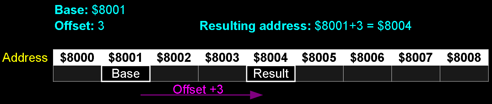 Using a Base plus an Offset, the resulting address used in the operation will be the sum of the two. |
Index Registers on 8 bit systems
8 bit systems frequently offer this 'Base Pointer + Offset'
addressing via special 'Index Registers', these allow us more
flexibility for specifying the source or destination of our
parameters.
For Example: The Z80 has IX as an Index register. Let's look at the Z80 command "LD A,(IX+7)" which sets the Accumulator. If IX=10 then the Accumulator will be read from address 17.
The advantage of this is that code using index registers can be 'reused' easily. If we have a 'ShowSprite' function that uses IX, we can point IX to each of our objects we want to show, and the code can be designed to find the relevant settings for that object as relative offsets.
The 6502 also has registers for this purpose. X and Y are used for similar purposes.
Absolute Addresses and Relative Addresses
In our code there will be many times we will need to specify addresses, either for reading or writing data, calling subroutines, or branching on conditions. In 8 bit code, these will tend to be Absolute Addresses - addresses at a fixed location.
Relative addresses are specified as an offset to the current position in code (the PC register). These are only really used for jumps and branches in 8 bit code (not subroutines). 16 bit systems use relative code more often, as their programs are often 'relocatable' in memory.
Examples of Absolute addressing are:
|
Function |
Z80 Version |
6502 Version |
|---|---|---|
|
Load a value from address $1000 |
LD A,($1000) |
LDA $1000 |
|
Save it to $2000 |
LD ($2000),A |
STA $2000 |
|
Jump to address $3000 |
JMP $3000 |
JMP $3000 |
Examples of Relative addressing are:
|
Function |
Z80 Version |
6502 Version |
|---|---|---|
|
Jump to the address 16 bytes away if Z flag is set |
JR Z,16 |
BEQ 16 |
RISC and CISC CPUs
RISC stands for "Reduced Instruction Set Computer", CISC stands for "Complex Instruction Set Computer".
RISC processors tend to need more commands to do a single job than their CISC counterparts, but those commands will tend to occur faster, and the processor will be relatively simpler, meaning it's probably more power efficient.
Examples of RISC are the ARM,
RISC-V, MIPS and POWER PC.
Examples of CISC are the Z80, 68000 and 8086.
These terms aren't particularly helpful to the programmer, especially as the "RISC ARM" instruction set is more advanced than the "CISC Z80", they are just included in here to explain the term.
If you find yourself looking at ARM or RISC-V asking yourself "why isn't it as easy to do X as on the 68000?" then the answer is probably "Because it's a RISC CPU!"
Load and Store Architecture
'Load and Store' architecture is a
common feature of RISC processors like MIPS and RISC-V.
This refers to the fact that many of the data processing commands
only work between registers, so we need to load the values into
registers in one command, do our operation in a second, and if
needed store the result back to memory in the third.
This can feel a bit frustrating if we're used to 'Register and
Memory' systems like the 68000 or 8086, which allow memory
operations to be combined with calculations, as it is likely to make
our programs longer. However RISC systems are designed to gain
efficiency from this simplified range of addressing modes.
The Instruction Pipeline
| While not relevant to 8 bit and most 16 bit processors, Later 16
and 32 bit processors, like the ARM, 386 and 68040 introduced a
concept of Instruction Pipelining. This is where the processor loads future instructions while the current ones are still being processed, Generally this increases the speed, but it does cause some issues. |
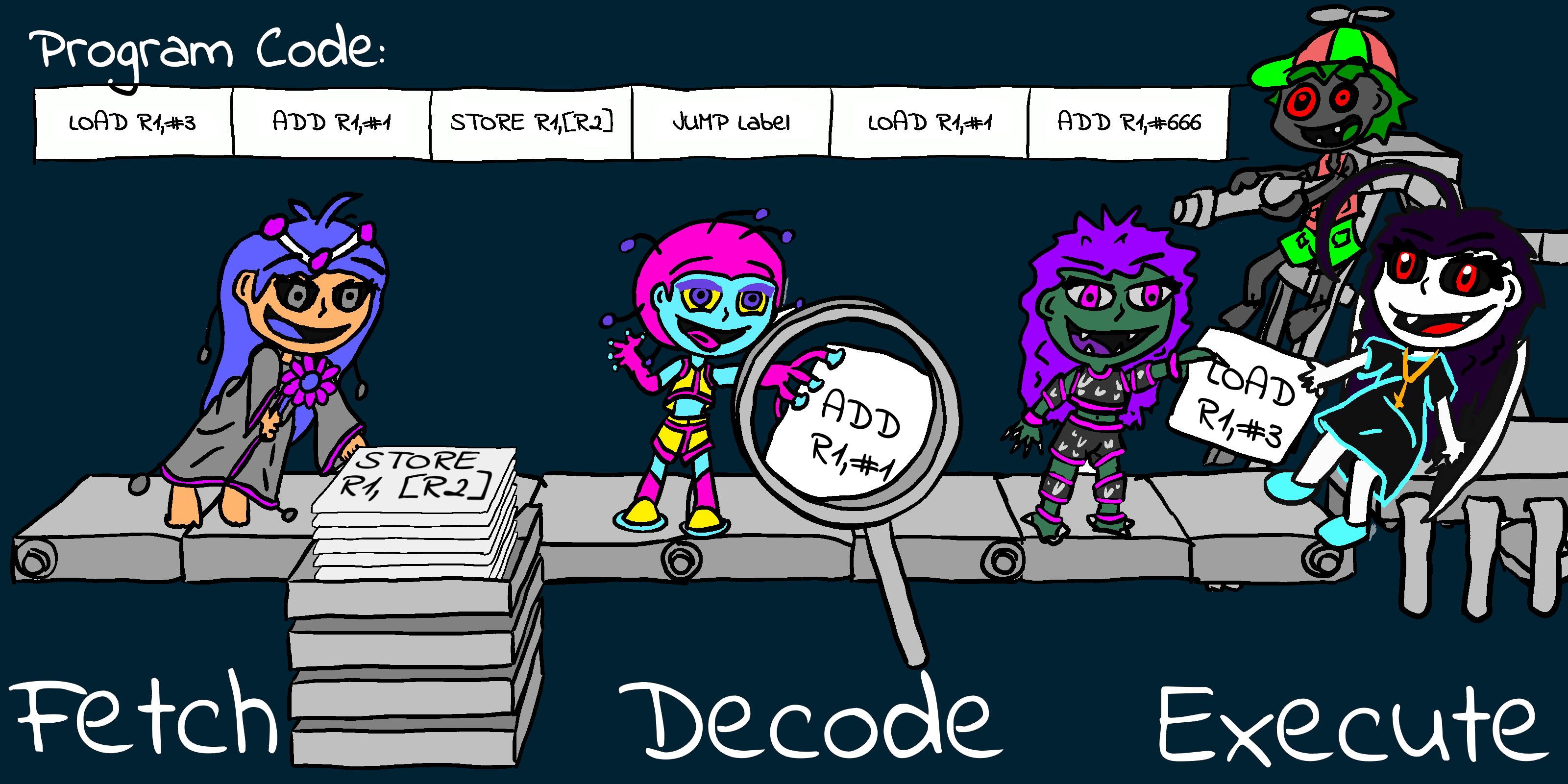 An imaginary processor with three stages: Fetch, Decode and Execute |
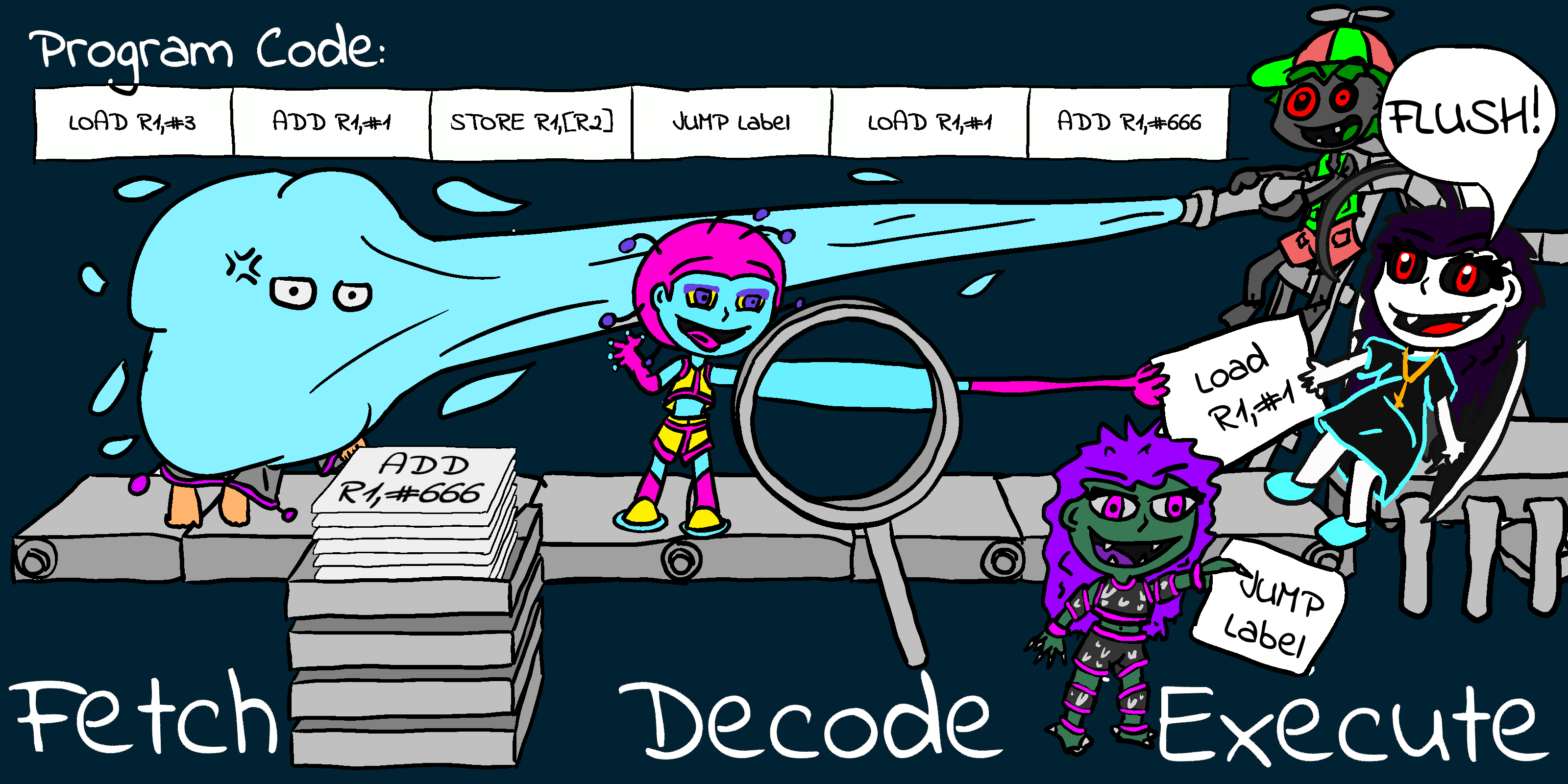
| Lets suppose we have an an imaginary processor that loads 3 instructions in advance before decoding. If the first instruction upon decoding is found to be a 'Jump' then the next two commands in the pipeline will not be correct. The processor will need to 'Flush' the pipeline of the not needed commands and refill the pipeline with commands from the address jumped to, slowing down execution. A technique known as 'Branch Prediction' can be used to reduce this). | 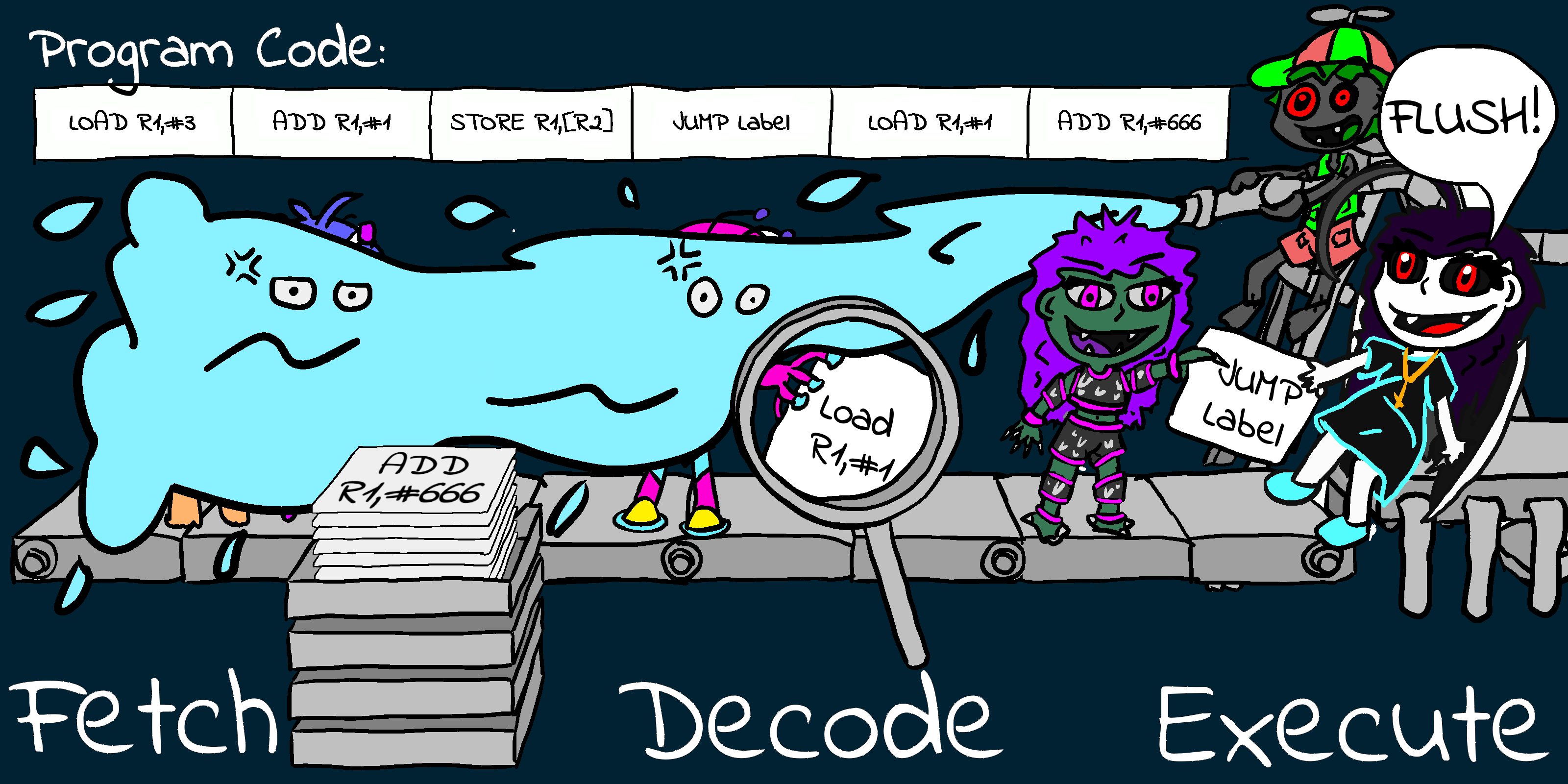 If the executed command causes a branch to somewhere else, the other commands which are in the pipeline should not be executed, as they are after the jump. The pipeline must be 'flushed' clearing out these commands, but wasting time in the process! |
| The ARM allows individual commands to be conditionally
executed, reducing the number of branches needed, and therefore
reducing the number of pipeline flushes. On the MIPS processor this causes a different problem, the concept of Delay Slots! Commands like Jump command should flush the pipeline, but it does not, and instead the command AFTER the jump is actually executed before the jump occurs. The jump is �Delayed� by one command to reduce the commands flushed from the pipeline. This is sometimes referred to as a Control Hazard. If we don�t want this to happen we can put a 'No Operation' (NOP) command after the jump. Another MIPS side effect is Delayed Loads, where the command after a load cannot use the register that was loaded, as the load may not have actually occurred yet! This is sometimes referred to as a Data Hazard. |
 Processors like the SH2 and MIPS use a 'Delay
Slot' after a jump. When the code branches somewhere else, the
command immediately after the command causing the jump is
executed anyway! While this makes the code a little difficult
for us to read, it increases the efficiency of the processor,
as less loaded commands are wasted by the flush. Processors like the SH2 and MIPS use a 'Delay
Slot' after a jump. When the code branches somewhere else, the
command immediately after the command causing the jump is
executed anyway! While this makes the code a little difficult
for us to read, it increases the efficiency of the processor,
as less loaded commands are wasted by the flush. |
This is all rather confusing, but fortunately delay slots only affect a few CPUs such as MIPS and SuperH (SH2/SH3), you don�t really need to worry about the Instruction Pipeline on other systems.
Decimal
Decimal is what we're used to - the 0-9 numbers on our clock, our
receipts, and our normal calculator.
It's known as 'Base 10', as each 'digit' has a value of 0-9.
Binary
Binary is Base 2. Each digit can only be 1 or 0.
"01" in binary is 1 in decimal, "10" in binary is 2 in decimal, "100"
is 4, "101" is 5 and so on.
This works better for computers, which tend to work in only 'Off' or
'On'.
In Assembly, Binary is often shown starting % . You may see 2 in binary shown as "%00000010", though other assemblers used different terminology, so you may see the same value as "00000010b" or "0b00000010".
Hexadecimal
As computers work in Binary all our registers and memory values
will contain values made up of a number of bits. 8 bits would have a
decimal range of 0-255, and 16 bits would have a decimal range of
0-65536.
These may not always be the most 'clear' way to represent these
numbers, which is where Hexadecimal comes in!.
Hexadecimal is 'Base 16', and this is the way
computers combine binary bits into digits we can easily use in our
source code, it effectively represents 4 bits as a single 'digit'.
It uses the normal digits from 0-9, then uses letters 'ABCDEF'
as 'digits' for 10-15. '&10' in hexadecimal is "16" in decimal!
Depending on the Assembler syntax, the way we identify a Hexadecimal number will vary. Hexadecimal is often shown starting with a '$' or '&', or sometimes '0x', or ending in 'h'. You may see the Decimal value 31 shown in hex as '$1F', '&1F', '0x1F', or even '01Fh'.
Octal
Octal is Base 8. It's not really used any more, but it's worth
remembering the name as you'll hear it from time to time.
If you�re learning PDP-11, however, then it becomes pretty essential,
as the hardware and instruction set is entirely oriented around Octal,
so you�ll pretty much have to use it.
'255' in decimal is '377' in Octal. 65535 in decimal is '177777' in octal.
On the PDP-11 the instruction set is structured around 3 bit
'clusters' which makes using Octal very logical. Apparently it was
also convenient as it allowed bit representation of values on old LED
displays that could only display digits 0-9, and therefore couldn't
show Hexadecimal.
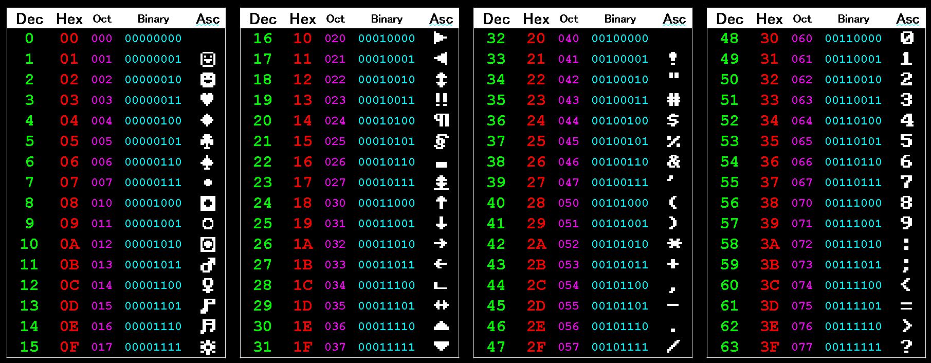
ASCII
ASCII stands for "American Standard Code for Information Interchange".This is what you're reading right now! It's just regular letters, numbers and symbols.ASCII defines the first 128 characters in the character set, but many computers allow 256. The second 128 are different on each system.
Note: some systems, like the C64, do not use ASCII, they have a different character set.
As our assembler will probably convert letters to ASCII bytes, this may mean strings of text we put in our ASM code do not appear correctly on screen. We will either need to use an assembler that can work with this, or to write our code to convert ASCII to the matching letters on the system.
Byte (Bytes)
A byte is 8 bits. An unsigned byte can represent a value from 0
to 255 in Decimal, which is $00 to $FF in Hexadecimal, or %00000000 to
%11111111 in Binary.
A signed byte will have a value from -128 to +127 in Decimal.
A byte is the smallest unit of memory in a system. Registers on an 8 bit system work in bytes, and each CPU memory address refers to a byte of data. Address $0000 is the first byte of memory, and $0001 is the second, and so on.
Bit
| A bit is a single binary number 1 or 0, there are 8 per
byte. Bits in a byte or word are numbered backwards from right to left. In a byte, Bit 0 is the least significant (with a value of one), Bit 7 is the most significant (with a value of 128). |
 Numbered Bits in a Word and their respective value. You'll need to know the position numbers for bit testing commands, and reading hardware documentation. |
Nibble (Nybble)
| A Nibble is half a byte, that's 4 bits. A nibble can
therefore have a value of 0-15, or $0-$F in hexadecimal. Note: There are always two in a byte, there is no such thing as a system that has a 1 nibble register, or 1 nibble per memory address. The unit 'Nibble' is of course a pun on Bite and Bit, disappointingly there is no such unit as a 'Munch'! |
 Nibbles in a byte. Nibbles are always 4 bits, so there are two per byte. |
Kilobyte
A Kilobyte
is 1024 bytes.
You may ask why isn't it 1000 bits? Well, because numbers in computing are made up binary, decimal 1000 wouldn't be very convenient for representing the numbers we'll frequently need to use. 1000 in hexadecimal is $3E8, but 1024 is a much more tidy $400!
Our 8 bit machine with its 16 bit address bus has a memory limit of65536, 64 Kilobytes (64K).
The abbreviation for Kilobyte is KB.
Kb (lowercase
'b') is kilobit (1024 bits - 128 bytes). This is sometimes used in
documentation relating to data transfer speeds or memory capacity and
can make things rather misleading!
Even more annoyingly, sometimes 1 Kb is referred to as 1000 bits,
not1024. When referring to speeds 1 Kb is usually 1000 bits, when
referring to memory 1 Kb is usually 1024 bits.
Strictly speaking 1024 bits is referred to a 'Kibibit' (1 Kibit) � though personally I've never seen this term actually used!
|
Unit |
Bytes |
|
Unit |
Bytes |
|---|---|---|---|---|
|
1 KB (kilobyte) |
1,024 |
|
1 Kb (kilobit) |
128 |
|
1 MB (megabyte) |
1,048,576 |
|
1 Mb (megabit) |
131,072 |
|
1 GB (gigabyte) |
107,374,1824 |
|
1 Gb (gigabit) |
134,217,728 |
Word
The size of a word depends on the system. On 8 and 16 bit systems
(Z80/6502/68000) it's 2 bytes, but on 32 bit systems, like ARM, it's 4
bytes.
A word on an 8 or 16 bit system goes from 0 to 65535, or $0000 to
$FFFF in Hexadecimal.
A signed word on an 8 or 16 bit system goes from -32768 to +32767.
A word on a 32 bit system goes from 0 to 4,294,967,290, or $00000000 to $FFFFFFFF in Hexadecimal.
Long / Double Word
A Long is two words. On 8 and 16 bit systems this is 4 bytes. On
systems like ARM it's 8 bytes.
A Long on an 8 bit system goes from 0 to 4,294,967,295, or $00000000
to $FFFFFFFF in Hexadecimal.
A signed Long goes from -2147483648 to +2147483647 .
Signed Number
A Signed number is a number that can be positive or negative.An Unsigned 8 bit number can go from 0 to 255 but a signed number can go from -128 to +127.
The way signed numbers work in assembly is odd, and exploits a 'quirk' of the way the processor registers work.
A byte value in an 8 bit register can only go from 0 to 255. If we add a large number to a byte register (for example adding 255 to 128), the register will 'Overflow'.
This 'Overflow' does not cause any kind of 'error' as the value in the register simply goes back to zero, then 'carries on' counting up.
This means when we add a large value to a register, we will actually end up with a smaller number, and in this way adding 255 to an 8 bit register is actually the same as subtracting 1!
So 255 is effectively -1, 254 is effectively -2 and so on.
The processor doesn't 'know' whether the 255 in a byte register is -1 or +255, and it doesn't need to, as we use different condition statements for signed and unsigned numbers, and we code according to whether our byte is signed or not.
Don't worry if that sounds odd, it will make more sense later!
Converting a positive to a negative is easy. In code we flip all the bits via an XOR / EOR or other special command (like CPL), and add one to the result with an INC or ADDQ (or equivalent). This is known as Two's Complement.
For Example: Let's look at converting 1 to -1. Our register starts with a decimal value 1. After the bits are flipped and one is added this will result in a decimal value of 255 ($01 converted to $FF in hexadecimal).
If we want to calculate the byte or word value a for a negative number on our calculator we take the maximum value plus 1 (256 for a byte, 65536 for a word) and subtract the number we want to negate.
For example to get the value of -10 we would calculate 256-10 = 246 ($F6 in hexadecimal).
Binary Coded Decimal
Working in hexadecimal is great for mathematics and calculating memory addresses, but it's difficult for showing decimal numbers on screen.Suppose we use a 16 bit number for our 4 digit game score, how can we easily split the score 65535 into 4 decimal digits quickly for display? Unfortunately we can't! It would be slow and take lots of divide commands, something very difficult on 8 bit processors.
This is where Binary Coded Decimal (BCD) comes in!
With normal register values, if a byte has the value $73 in hexadecimal, it's decimal value will be 115.
In Binary Coded Decimal each 4 bit nibble is a single decimal digit, so the value $73 in a byte is actually the value 73 in decimal! This makes it very easy to convert numbers for display.
We've effectively ignored the A-F part of the hexadecimal numbers. As a result Binary Coded Decimal 'wastes' some memory, as now a byte can only store 0-99, but it's a much easier way to store data which we need to convert to decimal digits to ASCII for display.
There are two Binary Coded Decimal formats:
Packed format stores two digits per byte. In this format the decimal value '1234' would would take 2 bytes, and would be stored '$12 $34'. This is the most common BCD format.
Unpacked format stores just one digit per byte. In this format the decimal value '1234' would take 4 bytes, and would be stored '$01 $02 $03 $04'.
Assembly Source file
| The source file is a text file which contains
the commands that make up our program, usually with an ASM file
extension. We can't run an ASM file on an emulator or computer,
we'll need to convert it to a binary file with an Assembler.
We can edit the file with whatever we prefer, Notepad, Notepad++ or Visual Studio Code, it's the Assembler that does the 'real work' of making a runnable program. |
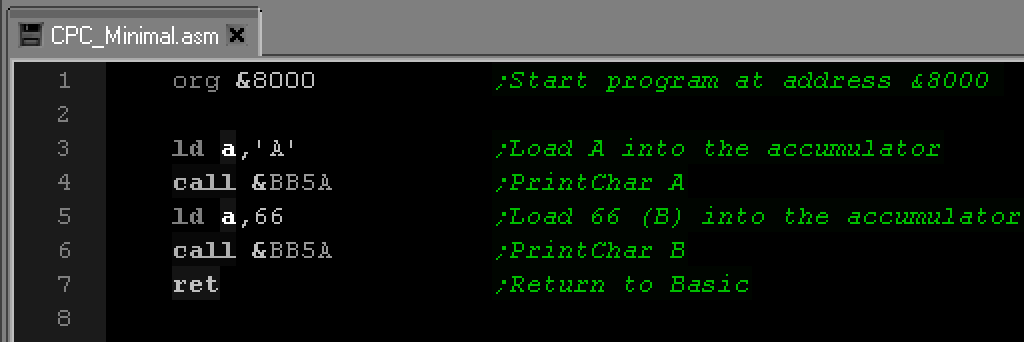 An ASM source file being edited with Notepad++ |
Binary file
| A binary file is pure data, the content could be any kind of data. Binary files could be an image, some sound or even a program our retro computer can run. We'll need to know what to do with it to make use of it, a sound file copied to video RAM won't help much! | 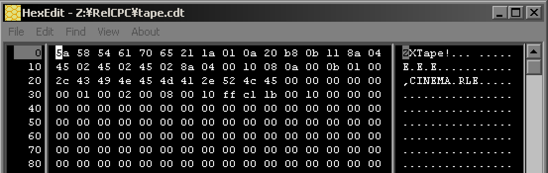 This hex editor shows bytes as Hexadecimal and their ASCII equivalent. |
Assembler
| The Assembler will take a source file
(usually with an ASM file extension) and convert it to binary
data.
On a cartridge based system we may end up with a usable game once it's assembled, but on home computers we may need to do more work, like add it to a disk or tape image for our emulator to run. |
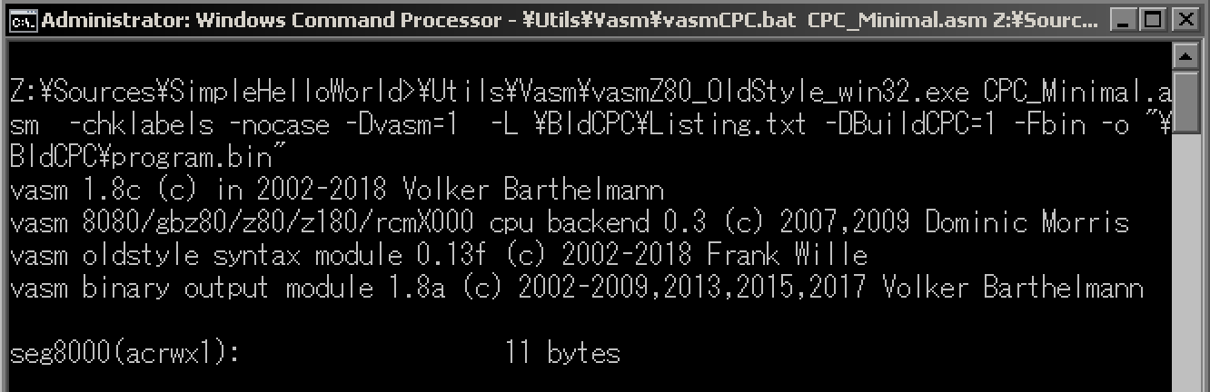 VASM and most other assemblers are command line tools. |
Compiler
Compilers often make up part of a �high level language� toolchain (Like Basic or C++).
They will take the high level
language source code, and convert it to Assembly source code (a low
level language), which an assembler will then covert to Assembly.
Linker
Depending on your destination file format and Assembler, assembly may not be enough to produce a runnable program.
A linker can take multiple files, combine them together and produce a runnable file.
Debugger / Monitor
| A Debugger is a tool which helps us figure
out what is happening in our program, typically when there's a
'Bug' (something going wrong).
They will often show the contents of the CPU registers, the running code (via disassembly) and allow us to see parts of the memory. They may also allow us to 'step' through the code, running just one line at a time to see what's really happening. Debuggers are also sometimes called 'Monitors', in the sense they monitor the running state of the code. |
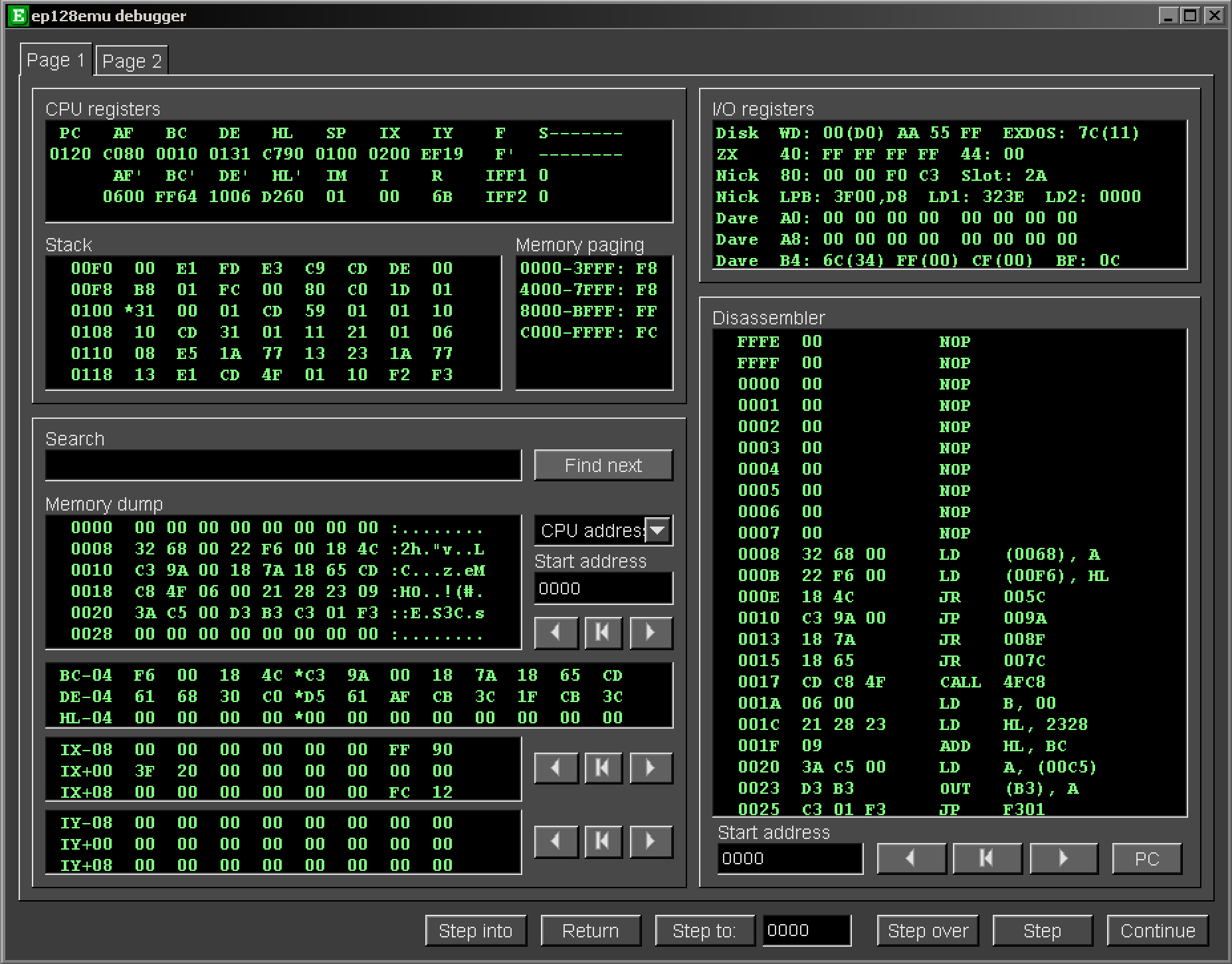 The very comprehensive debugger of ep128emu. Not all emulators have such good functionality! |
Listing File
| A listing file is a summary of how the ASM
source converted to output bytes, it also typically includes the
symbols like a symbol file.
Assemblers don't usually output these by default, but they can be essential to figure out what's going wrong when things don't happen how you expect. |
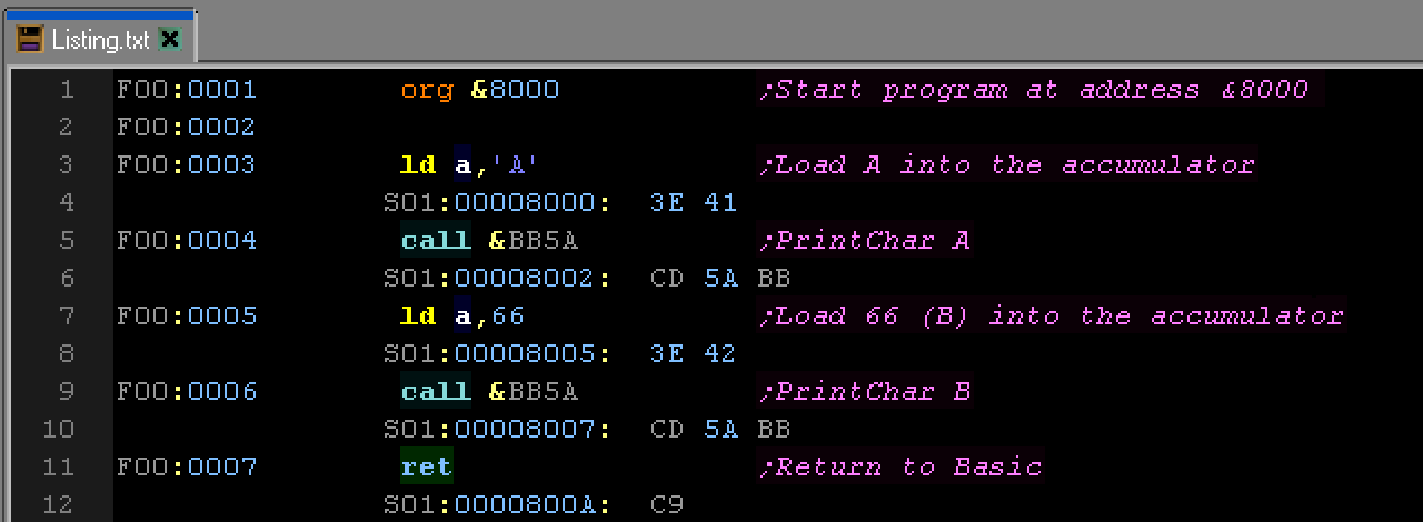 A Listing file, the source code and the resulting bytes are shown. |
Symbol file
|
A symbol file contains the names of Labels and Symbols, with the text name and resulting byte value. A symbol file can be used with a Disassembler or debugger to keep the label names in disassembled code. You don't need symbol files to build your program, however if things don't work as expected, they can help you identify what's going wrong, and also help you learn more about how the assembler compiles the source to resulting bytes. |
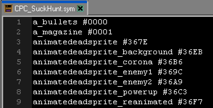 The optional Symbol file. This tracks all the values that the symbols and labels ended up with. |
Disassembler
| The Assembler converts a source file to a binary so we can
run it, Binary files don't make much sense to humans though and
we may want to see how a program works that we don't have the
source for. That's what a Disassembler does!
The Disassembler takes a binary file and converts it to a Source File. Unfortunately it doesn't do a perfect job. Label names, Symbols and Comments are not included in the binary, so these are all lost. Also it can be hard for the Disassembler to work out what parts of the binary are program code and what parts are images, sound or other data, and it may mix the two up. If you have a "Symbol File" from the assembly stage, the Disassembler will be able to recover these label and symbol names, which can help for real time disassembly of a program while it's running. |
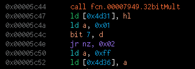 A disassembled file - but the labels have been lost for the addresses |
Disk Images and Tape Images
|
Our home computers probably can't run a binary 'as is', we'll need to make it into something the computer can use. We'll need to put our binary onto a 'Tape' or 'Disk'. We won't use a real one though, we'll use a fake 'Disk' or 'Tape' image. We'll need special software to make this Disk or Tape image. Unfortunately, Disk, Tape and Cartridge formats are platform dependent, there's not 'one solution', so you'll need to check the documentation relating to the system you're interested in. |
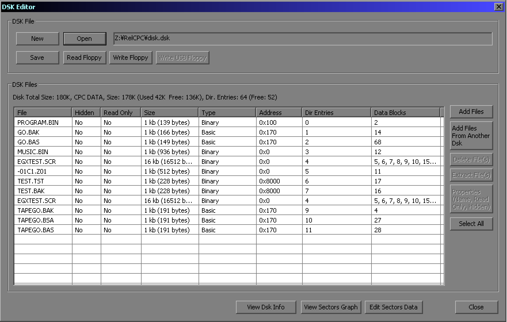 Amstrad CPC Disk Image Editor: CpcDiskXP. Unfortunately you typically need a different disk image editor for each system. |
Immediate Value
An 'Immediate' is a fixed number parameter specified in the
assembler source after the command.
For Example: Let's look at the commands "LD A,3" (Z80) or "LDA #3"
(6502).
In these examples the value 3 is an 'Immediate'.
Other commands like the commands, "LD A,(3)" or "LDA 3", are loading from the address '3', so these are not Immediate values.
Don't worry if you can't tell Immediate values from values loaded from addresses at this stage, as the syntax varies depending on the assembly language you're using.
You'll notice on the 6502 and 68000, Immediate values start with a "#", and if you forget that symbol the value will be be treated as an address. This is a common mistake you're likely to make, so it's worth double checking when things go wrong!
Label
| A label marks part of the code which we will refer to
later, it's like a line number in Basic. Usually it's a
destination for a jump (a command like GOTO in Basic) or some
data we'll read or write elsewhere in our code (like sprites or
variables).
Typically (unlike command opcodes) labels have to be at the far left with no tab indent, and have a colon after the label. |
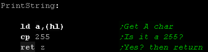 A label called "PrintString" - we'll CALL this later in our program. Note the label is at the far left, but the code is indented by at least one tab. |
Operator
| An operator is a 'command' like ADD or SUB. The
abbreviated commands used in Assembly are called 'OP Codes'. Commands in Assembly typically need to be 'indented' with a tab to identify them as not being labels, though this can vary depending on your assembler. Note: You may see �Opcodes� referred to as the �Byte data� that the command assembles to, and the human readable command referred to as an �mnemonic� For example, the Z80 mnemonic �NOP� assembles to the byte opcode �&00� |
 LD, INC and OUT are operators. |
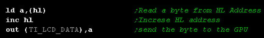
Operand
| An operand is a parameter, often a Register or an Immediate value. | A, HL and TI_LCD_DATA are operands - the parameters of the operator. |
Assembler Directives
| Assembler directives are commands which instruct the
Assembler to do something. These are not converted directly to
command bytes for the CPU, instead they change the function of
the Assembler and tell it how to assemble
the code.
There are a wide range of assembler directives, and their format will vary depending on the Assembler, but some examples are: "EQU" (Symbols) "IFDEF" (Conditional Compilation) "ORG" (tells the Assembler the address the code will run from) ".186" (tells the Assembler what version CPU we're compiling for) and "DB" (Defined Bytes of data).
|
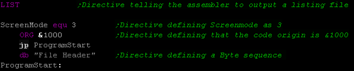 There's a huge range of Assembler directives, depending on your CPU, Assembler and syntax choice. The only thing you can do is check your Assembler's manual. |
Symbol
| A symbol is a fixed value (it doesn't change during our
code). "PI EQU 3.1415926" sets the symbol "PI" to the number
3.1415926. We can now use PI in our code, rather than typing all
those numbers again.
It's the assembler that converts the symbol, the binary file will not change whether we use the number or the symbol in our code. EQU stands for 'EQUate' or 'EQUivalence', it tells the assembler the symbol has the same value as the number which follows. The exact syntax of the command varies depending on your assembler. In VASM, EQU statements have to be at the far left like labels. |
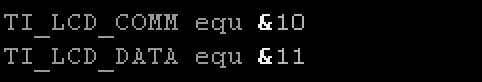 Two Symbols defined for the TI graphics ports. |
Code Comments
| There will be times we will want to put notes within our
code so we can remember how it works. These are known as
'Comments' or 'Remarks' (REM statements).
While the syntax varies depending on your assembler, comments in assembly usually start with a semicolon (;). They can be on a line on their own, or at the end of a line of code. After the semicolon, the assembler will ignore the rest of the line, so adding a semicolon to a line of code will quickly disable it. These are totally optional, they make no difference to the resulting program, but you will probably find them essential to help make the function of the code you're writing clearer, as when you're debugging it in a few weeks, or trying to reuse part of your old code many months later, you'll benefit from having spent the extra time to add at least a few comments to your code. |
 Code comments can be a whole line, or after a command. On most assemblers a comment starts with a semicolon (;). |
Conditional Assembly
|
There may be times when we want to build multiple
versions of our program from the same source. We don't want to keep two separate copies of the source files, as this would increase our developing and maintenance time, instead what we do is use 'Conditional Compilation'. By using assembler directives, such as "IFDEF mysymbol" (IFD on 68000) and ENDIF, we can define blocks of code which will only assemble if a symbol is defined. By defining only certain symbols, we can enable and disable these blocks, changing the code that is assembled, and the resulting program. Enabling and disabling symbols can be done by simply putting a semicolon (;) at the start of the line, turning them into comments, or symbols can often be defined on the assembler command line, meaning we can run different scripts to build different versions of our code. |
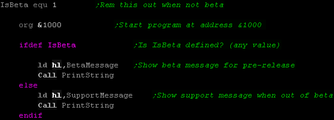 Conditional assembly allows us to make it possible to have one source file that can have different build versions. |
Macro
| A Macro is a bit like a symbol. It defines a set of
commands that are given a 'name'.
We can then use that name in our code and the assembler will replace it with all the commands we defined. For Example: We could create a macro that automatically prints a letter and call it PRINTCHAR. We can then use PRINTCHAR 'A' or PRINTCHAR 'B' in our code. The Assembler will use our definition to produce the resulting program with the contents of the macro replacing this. It's a bit like making our own commands. It saves us copying the same code over and over and it saves a bit of time, rather than writing a subroutine. The syntax of a macro definition depends on the assembler. You'll need to check the documentation of your Assembler. |
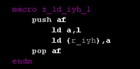 We've defined a macro "z_ld_iyh_l". When we use this name the assembler will 'put in' all the commands we specified here. |
Defined Data
There will be times when we want to put sections with byte data in our code. These could be values for lookup tables, addresses for indirect jumps, or bitmap data.
The assembler directives we use to do this will vary depending on our assembler, but 8 bit assemblers often use DB and DW for Define Byte and Define Word.
DS (Define Storage) will define a block of data (usually initialized to zero). For example to define a block of 512 bytes DS 512 could be used.
On 16 bit systems the syntax is often DC.B, DC.W and DC.L for Define Constant Byte, Word or Long.
DS.B, DS.W and DS.L can be used to define a block of 8, 16 or 32 bit data.
For example: "DS.W 100" will define 100*16 bit words, 200 bytes total (the same as "DC.B 200" would).
A similar concept on 68000 systems is the BSS Section. This stands for 'Block Started by Symbol', though that doesn't really make its purpose clear. The BSS section is an area of memory which is allocated to our program but starts with zero values, so we can use it to store our sprites or level data, but we could use it for a screen buffer.
Indirection / Pointers / Vector Tables
| Indirection is a common way of using
registers for 'lookups'. This is where a register contains an
address to look at for the source or destination value for a
command.
It's kind of like going to the cupboard, and finding a note saying 'The pickles are in the fridge'! Pointers (like those used in C and C++) are a form of
indirection, and this kind of functionality is frequently used
in assembly as well. 'Vector Tables' are used by interrupt handlers on some
CPUs like the 6502, they are effectively a list of address
pointers. |
 Indirection on the 65c02. The data is read from the address at an address. |
Jumps and Branches
| Normally after each command the CPU will run
the next command, but there will be times we need to jump
elsewhere. Unconditional jumps will ALWAYS jump to a different place, this is like a 'GOTO' command in Basic. Conditional jumps will SOMETIMES jump, depending usually on one of the flags registers. This is like the 'IF THEN GOTO' commands in Basic. Depending on the processor and command, There are two kinds of Address that you may come across, 'Absolute' and 'Relative'. On an 8 bit system, 'Absolute jumps' use a full 16 bit address, meaning the destination can be anywhere in memory, but 'Relative jumps' use a signed 8 bit offset, and are relative to the current line of code. This result in smaller files and code is relocatable, but can't jump very 'far' forward or backward in code (-128 bytes to +127 bytes). On processors like the 6502, 'Jumps' use an absolute address, meaning a full 16 bit address is used, but 'Branches' are relative jumps, and use a signed 8 bit offset, limiting the possible range of the branch. |
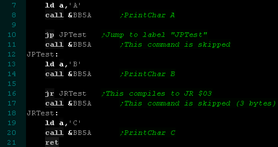 Absolute and Relative jumps in Z80 code. The Assembler converts the labels to numeric Addresses and relative offsets. |
Subroutines
| Subroutines are a bit like a JUMP � however
these will run part of the code, and then come back when return
occurs. This is like GOSUB / RETURN in Basic.
Subroutines are completely essential! When we write our program, we'll need to break up the problem. Suppose we want to show the message 'Hello'. We'll probably run a 'PrintString' subroutine, that will probably make multiple calls to a 'PrintChar' subroutine which may call a 'DrawPixel' subroutine! We write and test each subroutine separately. Once we get 'PrintChar' working right, it's no harder to use than the PRINT command in Basic. |
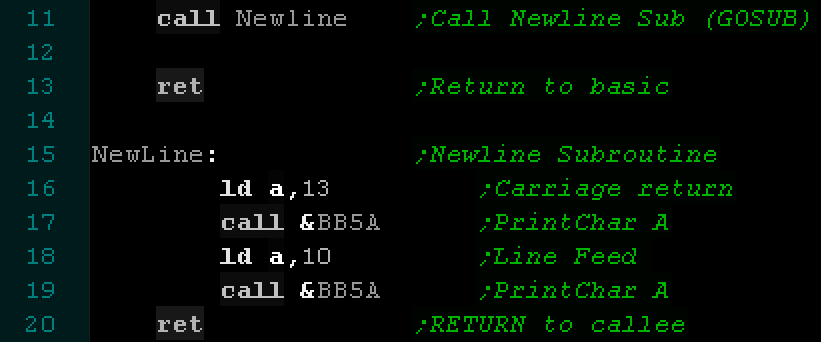 This example calls a subroutine called Newline. |
Self Modifying Code
| Self Modifying Code is code which changes
itself. This is usually done to improve speed, but also saves
memory.
For Example: Suppose during our game we have to check either the keys or joystick, depending on the option selected. We could read the 'controller' byte, and call the Key routine, or the Joystick routine, but it would be quicker to call the Key routine and rewrite the call if the player enables joystick. This will save a few bytes, and a little CPU power, but it makes the code harder to read. |
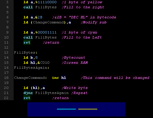 Here we've got a routine that draws 8 bytes of pixels to the right. The "INC HL" is changed to a "DEC HL" via self modifying code, and 8 bytes are drawn to the left |
Aligned Code
| There may be times when we want to specify
our code to be aligned on a certain byte boundary. For Example: We may want the bottom byte of our data to be a $00. So $1100 or $1200 is OK for our purposes, but $1180 is no good. We can do this with a command like 'ALIGN 8' which will align the data to an 8 bit boundary, meaning the bottom 8 bits of the new address will be zero. This is useful for times we're reading data from lookup tables, and when we want to only increase the low byte of a 16 bit address ("INC L" is faster than "INC HL"). The 68000 can only read words (including commands) on even boundaries (where the bottom bit is 0). This has a special EVEN command to do this (equivalent of ALIGN 2). Note: Other assemblers may use other syntax. For Example: VASM uses ALIGN 8, but WinApe uses ALIGN 256. |
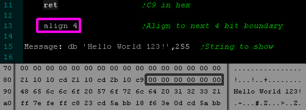 An example Align statement and resulting assembled binary. The "Align 4" has caused the 'Hello World' to start at $90. |
Bitwise Operations / Logical Operations
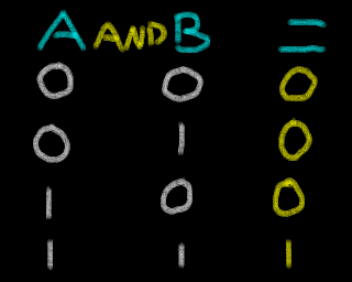
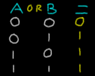
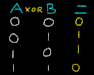
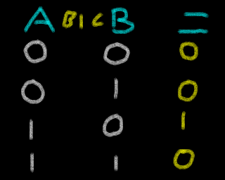
Bitwise Operations (also known as Logical Operations) are commands performed on all the bits of a parameter. Each logical Operation will take two parameters and the bits in the result will be the logical result of the two having the operation applied to it.
Different CPU's have a different operations available (Many don't have BIC), and sometimes the names may differ (XOR is often called EOR).
Here is how the result of common operations are calculated based on different source values
| AND | OR | Exclusive Or | Bit Clear |
| AND | OR | XOR / EOR | BIC |
 |
 |
 |
 |
| Lesson
8 - Programming Techniques Assembly programming has some common programming techniques and methods it's worth pointing out, as they may help you design your programs. |
|
Lookup Table
| A Lookup table is a table of pre-calculated values for some
purpose. They are used to save time where the calculation job
would be too slow.
Common uses for a lookup table would include Sine values, Multiplication calculations or transparency masking colors of sprite data, though there are any number of possible practical uses for lookup tables. For Example: Suppose we want to divide numbers between 0 and 279 by 7, and get a whole number (quotient) and remainder result. On an 8 bit CPU this will be very slow. If we can spare 280*2 bytes then we can pre-calculate the whole number and remainder for each value 0-279, and store them in pairs in the lookup table. When we need the answer, we just look at the correct offset, and the two values are there. |
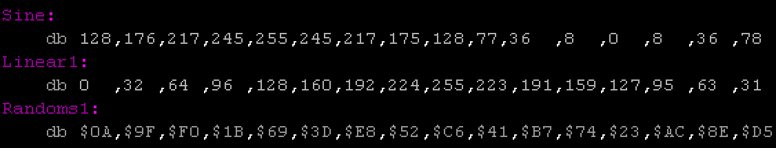 16 Byte Look up tables for generated movements. |
Jump Block
| A Jump block is a set of Jump commands at a specific
location. These jumps will have a defined 'purpose'.
For example: If we had a jump block at address $3000, we could have a jump to a ClearScreen function at $3000, and a Jump to DrawCharacter at $3003. Our code would call these addresses to perform the task required. The advantage of this is a later revision of the program could have completely different internal structure, but, provided the address and defined purpose of the jumps was unchanged, anything that uses the jump block would still work the same. For this reason Jump blocks are often used in system ROM, but we may want to use them in our own programs as part of our 'Game Engine', especially if we're making a 'Multi Load' game that loads each level separately, as it means we can make improvements later without changing (and recompiling) all our levels. |
 The ChibiAkumas Jump block with functions provided by the game core. |
Relocatable Code
When we assemble our program, often it will have 'Absolute addresses'. This means it must be loaded and executed at the address the code was assembled for (defined by an ORG statement or similar). If the code is loaded to a different address, then the Jumps will go to memory addresses which do not contain the commands they should.
For Example: Let's suppose our program starts at $1000, and there is a jump to absolute address $1010 ("JMP $1010" in 6502).
If we load this program to address $2000 then the "JMP $1010" command will still go to address $1010, and the code will not be there. (it would be at address $2020).
Sometimes we'll want our code to be able to move, and be run at any address in memory. This is known as 'Relocatable code'. To achieve this we need to ensure we only use 'Relative addresses' in our code *.
If our example program starts at address $1000, with a relative jump to +$10 ("JR $10 in 6502), but we load the program to $2000 the JR command will now go to the correct $2010. The program is 'Relocatable' and will work from any address.
The assembler can't help us with this, we need to only use relative commands in our code. If we always use commands like JR instead of JMP on the Z80, and BRA instead of JMP on the 65c02, then we can create a relocatable program.
* Note: Technically speaking some 68000 based systems CAN relocate absolute addresses, they have a 'Relocation' table which contains pointers to the bytes of code which are absolute addresses, and these are modified by the operating system before the program is executed.
| Lesson
9 - Graphics Terminology Lets look at some of the terminology we'll come across when it comes to graphics and video hardware. |
|
Sprite
| A sprite is an small moving image used in our
game. There are two types:
Hardware sprites are shown by the hardware. They are very
fast, and removing them is very easy, we just turn it 'off',
but there's a limit to how many are on the screen. Most
consoles 8 and 16 bit consoles use hardware sprites. 'Software sprites' are drawn to the bitmap video memory
by 'us'. We have to basically plot each pixel to the screen to
draw the image to the screen. When we want to remove them we
have to redraw the background where the sprite was. This is
slower, but there are no limits. Many 8 bit home computers
like the Amstrad CPC and ZX spectrum were not capable of
hardware sprites, so could only use software sprites.
|
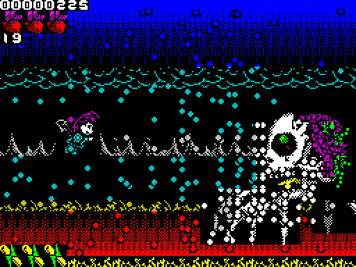
An imaginary platform game screen with tiles and sprites. Right: The final image is made up of 2 layers. The top layer is hardware sprites, The second is the tile map. |
Tiles, Patterns and Tile maps
| Hardware Tile maps are very common on console
and arcade hardware.
The Tile map is a grid type 'layer' of square 'tiles', usually 8x8 pixel squares. Each entry in the tile map is not a picture, it's a number which refers to a Pattern which is the tile bitmap itself. This saves a lot of memory, as a 32x32 tile map will take 1024 or 2048 bytes, but means there's often a limit to how many 'unique' tiles the screen can have. For Example: The Sega Master System would require 768 tile patterns to have a completely unique 256x192 pixel screen, but the master system only supports 512 tiles. This means any 'full screen image' will have to have duplicated squares (probably blank). 8 bit systems usually have just one tile layer, but 16 bit systems often have 2 or more. This allows for 'Parallax' where there's a foreground and a background that move at different speeds. You may think you've seen this on 8 bit systems, as many games with just one layer do clever tricks to simulate this effect! Just like with sprites, bitmap based computers can also use 'tile maps' but these will be software based, and therefore much slower than the hardware based ones. |
An imaginary platformer game screen. The tile map uses repeating objects, a star, a grass pattern, and a block - these are repeats of the same pattern. A 1 byte tile number can define this large area. |
Bitmap screens
A bitmap screen is an image where the visible contents of the screen are defined by a block of byte data in memory, and each pixel can be independently altered. This gives more flexibility than tilemap based systems allowing for vector 3d graphics and other complex and varied screens, but uses more memory than a tilemap.
Depending on the pixel depth, the number of pixels per byte will
differ.
A 256 color system will have 1 pixel per byte.
A 16 color system will have 2 pixels per byte.
A 4 color system will have 4 pixels per byte.
A 2 color system will have 8 pixels per byte.
This is only a general rule, some systems like the spectrum have 'color attributes' and there's a few bytes of 'wasted space' in the CPC screen memory area.
Let's compare different system memory usage:
The 320x200 4 color screen of the CPC takes about
16k.
The 256x192 16 color screen of the MSX2 and SAM Coupe takes 24k.
The Spectrum's 256x192 screen takes 6k.
This is part of the reason MSX2 games tend to be slow, and Spectrum
games are much faster than the CPC!
Color Attributes
|
Color attributes are a way of 'saving' memory but giving a more colorful screen. The Spectrum's black and white screen uses 6k of bitmap data and 768 bytes of color attributes. The extra 768 bytes turn a black and white screen into a color screen with 2 colors per 8x8 square. |
 Color attributes on ChibiAkumas on the ZX Spectrum, each 8x8 square only has 2 colors. |
Palettes
A Palette is a set of colors.
Typically our screen will be limited to 4 or 16 colors, but we can choose those colors
from a wider range (27 on the CPC).
Palettes are also relevant to consoles. A console like the SNES uses 16 color sprites, but each sprite can choose its 16 color palette from a wider range, giving 256 on screen colors! Doing so saves memory, as a 16 color per pixel image takes half the memory of a 256 color one.
Raster Beam
| Cathode ray tubes (old non flat-screen TVs) use a 'Raster beam' that scans the screen in a zigzag from top left, to top right and down the screen. |  The raster beam scans the screen from left to right, top to bottom - it happens so fast the eye cannot see the redraw. |
Many old games took advantage of this to perform 'clever tricks', changing things as the screen was redrawing. For Example: ChibiAkumas used this to get 16 colors on a 4 color screen. Other games use it to make the screen 'wavy' and systems like the C64, which has an 8 sprite limit, move those sprites the line after they've drawn to a new position, overcoming the sprite limit (ChibiAkumas also did this on the CPC+). |
 ChibiAkumas Ep2 Title screen. The screen uses 4 color mode, but 2 colors are changed 4 times during the raster redraw to make 12 colors appear. |
VBlank
| Vertical blank is the time after the screen
has finished drawing, but the next screen hasn't started yet.
On many systems this is the only time we can alter Video RAM, but 'waiting for VBlank' is also an easy way to limit the maximum speed of our game and stop it running too fast. There is also a 'HBlank' (Horizontal blank) between lines, however it is very short so not as useful.
|
VBlank and HBlank. |
CRTC
VDP
| Video Display Processor. This term is used by
some systems to refer to the 'graphics card' of the machine.
The VDP will often have separate memory from the main CPU, which cannot be accessed in the same way.
|
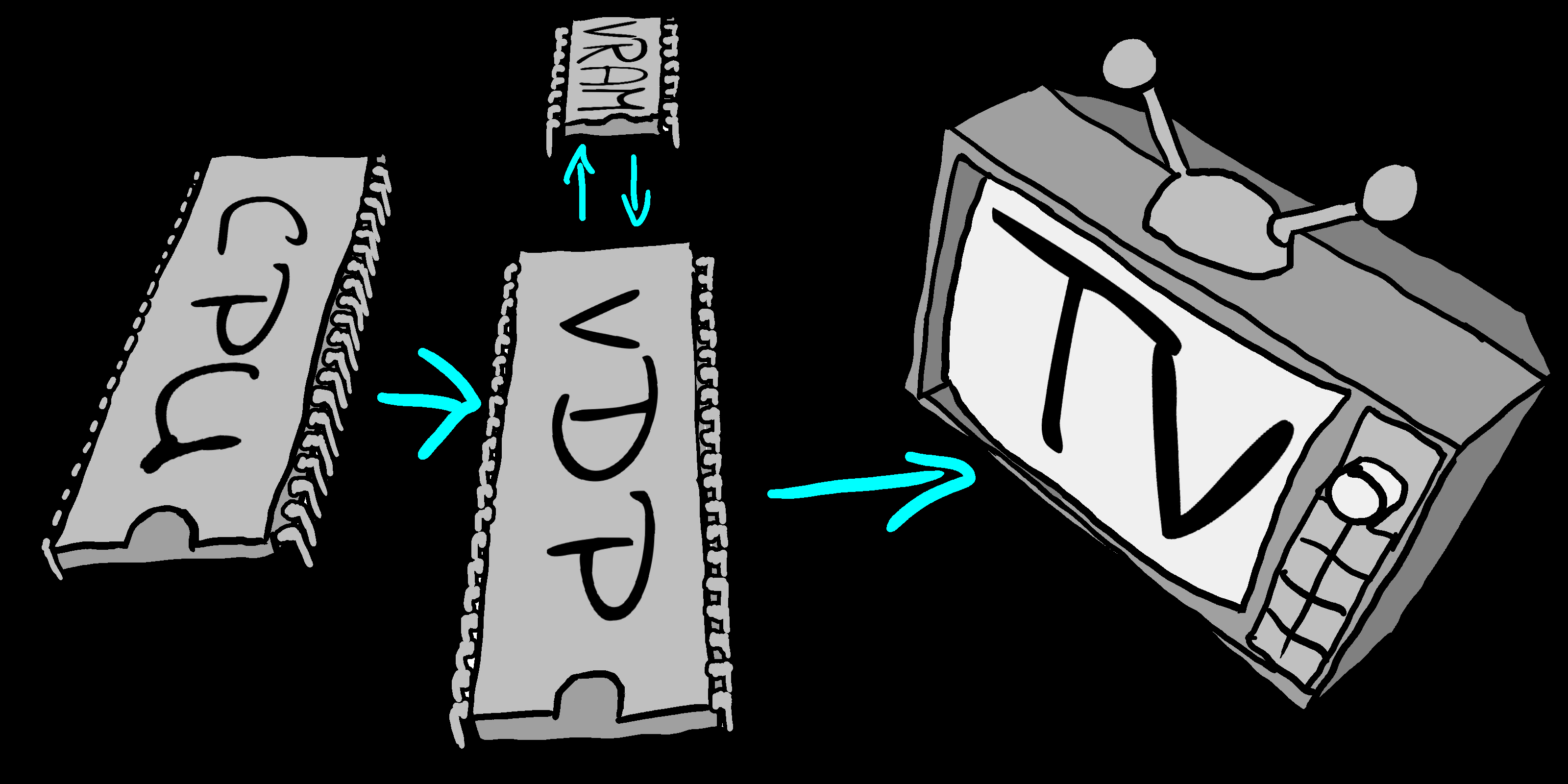 The CPU talks to the VDP which has its own memory, and generates the image for display. |
Bitplanes and Linear data.
| These are two different ways of storing image
data.
Let's suppose we have a system with 4
color sprites, 4 colors requires 2 bits per pixel (2bpp). 1. Store the two pixels for each byte together. This could be called 'Linear' data. 2. Store all the bit 0s for each of the 8 pixels in one byte, store all the bit 1s in a second byte. This is known as storing in 'Bitplanes'.
|
 Example of 2bpp as bitplanes or 'linear' data. Note: Some non-bitplane bitmap screens use other orders for pixel bits (Like Mode 0 of the CPC). |
Screen Buffer
A Screen buffer is the memory that makes up the bitmap screen. If we write data into this, the visible screen will change.
Double Buffering is where we use a pair of bitmap screens. One is the 'Visible screen' we show to the player, the other is the 'Drawing screen' which we update. Once the Drawing screen is completed, we flip the two buffers, showing the newly drawn screen, and using the previously visible screen as the new drawing screen.
Sound and Waveforms
|
Sounds are waveforms created by our speakers, and these are created by a Digital to Analog converter (DAC). If we have an oscilloscope we can 'see' these waveforms. The vertical axis of an oscilloscope view will be the 'Volume Level' and the horizontal axis is 'Time'.
|
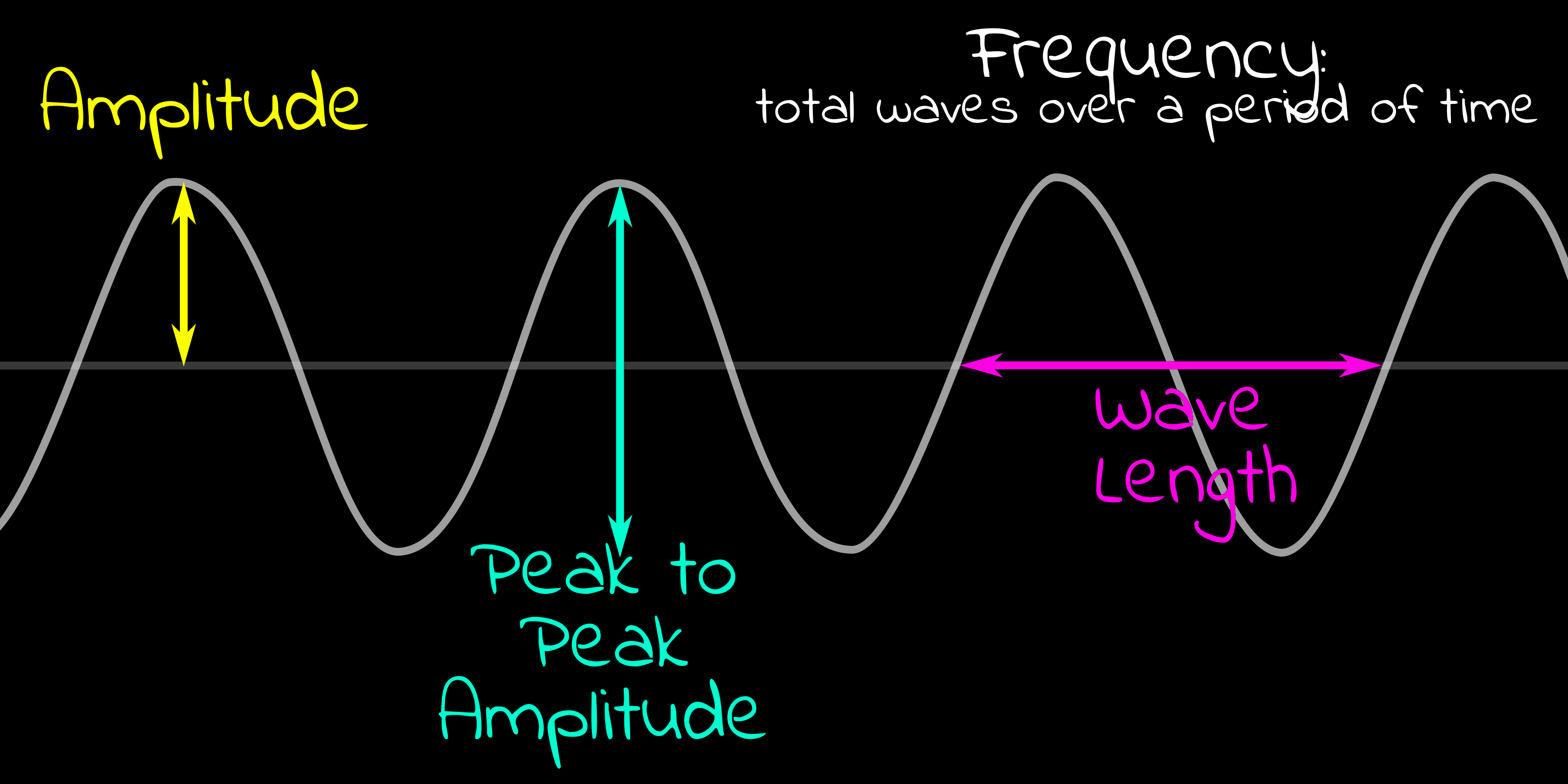 Figure 56: The 'Height' of a wave is known as the Amplitude (Volume to you and I!). The 'Distance between peaks' is the 'Wavelength', and the number of waves in a given period of time is the 'Frequency'. High frequency/Short wavelength is high pitch (treble) Low frequency/Long wave length is low frequency (Bass) 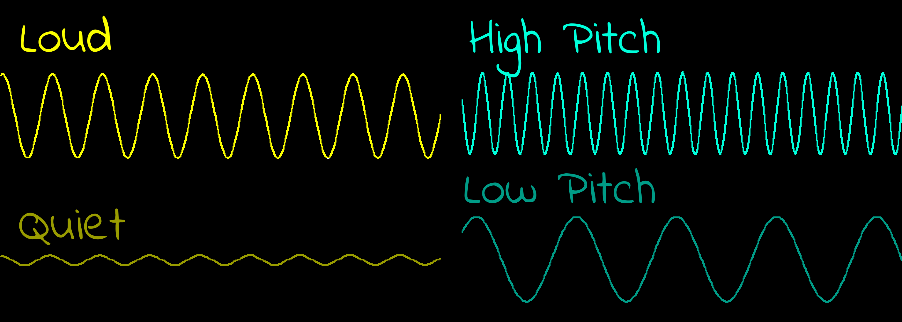 Figure 57: If we look at a fraction of a second, we'll see the shape of the tones. The 'Taller' the wave (Amplitude), the louder the volume. The 'Shorter' the wave, the higher the pitch of the wave |
Retro Sound Waves!
| Retro computers and their sound processors often create a
variety of simple 'instruments' which have very distinctive
waveforms. Most of these waves are 'named after' the shape they
appear!
The first of these is a 'Sine Wave'. This is the simplest wave used by FM synthesis, it gives a nice 'smooth' sounding note. 'Square Wave' is more artificial sounding and can sound a little harsh, it's the staple of sound chips like the AY-3-8910. It just repeatedly switches between 'Off' and 'On' at even times, so is easily created on systems with no dedicated sound chip like the ZX Spectrum. 'Triangle Wave' is used by sound chips like the C64 SID, it sounds a little less harsh than the Square wave. The 'Saw Tooth Wave' has a more 'buzzing' sound, these are also used by the SID. A 'Pulse Wave' is also similar to the Square wave, though the length of the peak of the wave, and time between waves differs, giving it a different sound. An honourable mention goes to 'Noise'! A noise wave will have apparently random amplitudes. Many sound chips will have some kind of noise generator which will create noise.Example sound samples: Sine , Square , Triangle , SawTooth , Pulse , Noise |
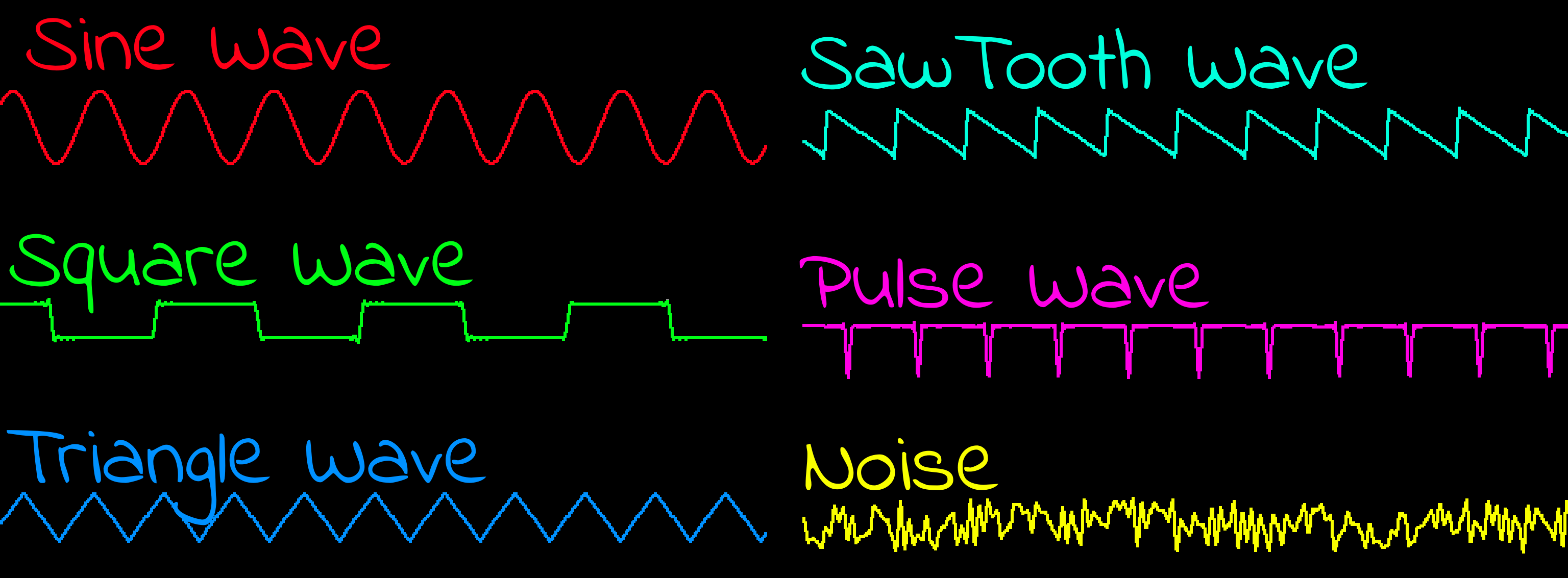 Figure 58: Various waves generated by the AY, ADLIB and SID, viewed using a software oscilloscope |
Beeper sound
The term 'Beeper' is often used to refer to computers which do not have a dedicated sound chip, and are only capable of simple sound, which is dependant on using the main CPU to build a wave form.
On the spectrum, we can only turn the sound 'on' or 'off' via a single bit. by switching the wave at timed intervals we can build a square wave in this way. The shorter the time between the switches, the higher pitched the sound, but as sound can only be on or off we can't really control the volume. Also unfortunately, as building the wave form requires constant CPU control, it's not really possible to play music during gameplay on these systems.
Some systems (like the Dragon 32/ Tandy Coco) have slightly more advanced sound� these have a Digital to Analog converter (DAC) which can take an output level (6 bits on the Dragon 0-63), these can be used to form more complex sounds and clear volume levels, however it still requires CPU power to play sounds.
Programmable Sound Generators (PSG)
Programmable Sound Generators refer to the more simple sound generators which produce sound with simple wave patterns like Square waves. Examples include the AY-3-8910 sound of the CPC & Vectrex, the SMS & BBC SN76489 and the C64 SID chip� these sound chips were also used on many other systems, and many later sound chips are backwards compatible with them...The NeoGeo is backwards compatible with the AY, and the Genesis is backwards comaptible with the SN76489.
As a dedicated sound chip is keeping the wave playing, the CPU can do
other things meaning the sound can play during gameplay!
Frequency Modulation (FM)
Frequency Modulation is the generation of sound by using oscillators to modulate a waveform making complex sounds far more 'realistic' than simple sine or square waves.
FM Synthesis was popular in home and arcade systems in the early 90's, before Wavetable synthesis became available in home computers.
MOD tracks and Wavetable synthesis
With the introduction of the Amiga and it's digital sound capabilities MOD trackers (Module Trackers) were born!� rather than using FM synthesis, these used a wave sample of an instrument (often sneakily ripped-off a music CD or LP!), To keep the tone when a key is held down part of the sample can be repeated, To make the pitch higher or lower, the speed the sample was played back was increased or decreased. However these relatively crude techniques often gave the notes an 'unnatural' sound.
Wavetable synthesis is a more advanced, but similar concept which uses a large bank of different sound samples, When playing a tone various samples are combined along with other techniques (usually in hardware) to produce more natural instruments. A simple example would be storing a different sample of an instrument at each octave, and pitch bending the sample within an octave, this would mitigate the artificial sound that would be caused when this is done in a simple MOD file.
Total level (Volume by another name!)
Volume is pretty fundamental to making sounds, but this is often referred to as 'Total Level' in sound documentation. This may also be called Amplitude.
Channels
Channels can refer to 'Left Speaker' and 'Right Speaker', but they also often refer to the number of 'Playing sounds' the hardware can manage at the same time. On some systems we can assign different Left and Right volumes to set the Left-Right Panning position, but on others like the CPC AY chip it's fixed with Channel A being 'Left', B being 'Center' and C being 'Right'.
Envelope
| In this case Envelopes have nothing to do with letters! In
music an Envelope affects how the sound changes over time. In many
cases, the Envelope will define how the volume fades, or ripples
after the tone starts, but it's also possible for envelopes to
relate to the pitch.
What options and capabilities for envelopes that are available will vary depending on your sound processor � If they are available at all!
|
 Figure 59: The AY-3-8910 Envelopes that can be applied to the channel volume, these can make a note fade in, fade out or 'wave' over time. |
Attack, Delay, Sustain, Release and K-On
| More advanced sound processors, such as FM synthesis, will
attempt to simulate the realistic sound an instrument will make by
adjusting the sound effect over time. For Example, Lets consider a real piano keyboard. The sound will start when you press the key. In programmable sound synthesis this is often referred to as K-ON. When you press a key, a hammer will hit a string in the piano causing a sound to occur quickly. This is known as the 'Attack' phase. Immediately after the key was pressed, the sound will quickly change for a short period. This is known as the 'Decay' phase. After a while, if the key is held down, the sound will 'level off', but the string will continue to vibrate. This is the 'sustain' phase. The point the key on the piano is released is known as K-OFF in sound programming. On our Piano when the key is released, the damper will stop the string vibrating, causing the sound to quickly silence. This is known as the 'Release' phase. To allow sound processors to create realistic sounds, it's common to see these stages represented, and configurable, on our sound processor. |
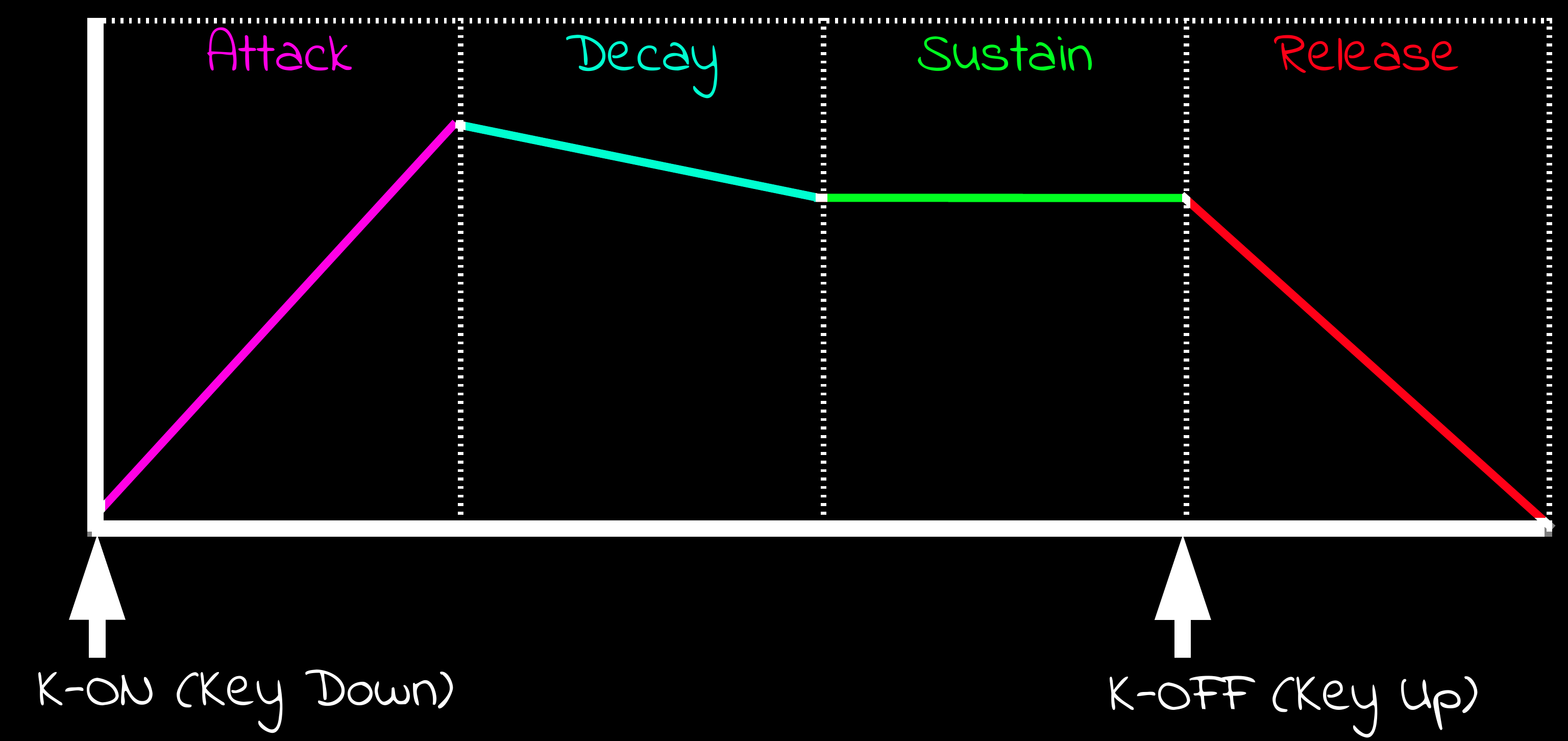 Figure 60: Typical stages of a sound across time as a key is pressed, and after it is released. |
Frequency Generators, Noise Generators, Envelope Generators
Many Sound processors will 'Build' a sound out of a combination of 'Generators'. These can be configured, and enabled and disabled as required based on the sound channel. Sometimes different channels on the sound chip will have different capabilities, if you look at the documentation of the sound processor you may see a block chart showing how the generators and channels link and combine to produce the sound.
LFO
A Low Frequency Oscillator is a low frequency signal generator which can be used to add a relatively 'slow' oscillating effect to sound. This can be affect the Pitch, Volume or even panning position
Tone and sweep
On some PSG based sound processors certain channels may offer a 'Sweep' function.
This allows the channel to affect the pitch of the tone over time, making it bend up or down.
Examples of systems that offer this function are the NES and Gameboy.
Octaves, Notes and key fractions
| Many sound chips allow use to produce sounds just with a numeric
'frequency' � we often just specify a number of 12-16 bits to
create a range of sounds from low to high pitch. However some
processors require us to work in notes and Octaves, and for the
musically challenged (like me) this can be a bit of a shock!
The Octave refers to the fact there are 8 notes between two notes of the same letter for example two 'C notes'.
It's easiest to think of the Octave when looking at a piano keyboard. Many of the notes have a black key 'Sharp' (♯) or 'Flat' (♭) key which is an 'In-between' note, which is a half 'step' up or down to the next note. C♯ and D♭ Of course, we may not want to make a sound that matches a clearly defined note, so it's likely that our hardware will offer some kind of 'Key fraction' to allow finely granular tones between two notes. You'll need to check the hardware documentation to see what options are available. |
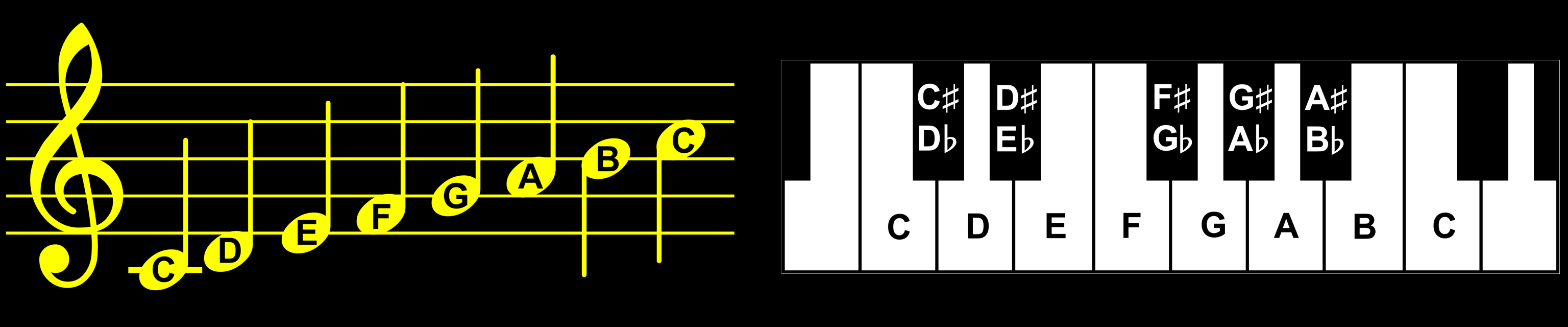 Figure 60: The Octave as shown in sheet music and a piano keyboard |
Operators and connections
| Fundamental to FM Sound generation is the concept of Operators
and Connectors. An Operator is typically the combination of an Oscillator, an Envelope and an Amplifier. We can configure an operator's frequency and volume to change the sound generated. Multiple operators are 'Connected' to form more complex � and hopefully more 'realistic' sounds. FM Processors will offer a variety of options for how the Operators are Connected to form the final sound |
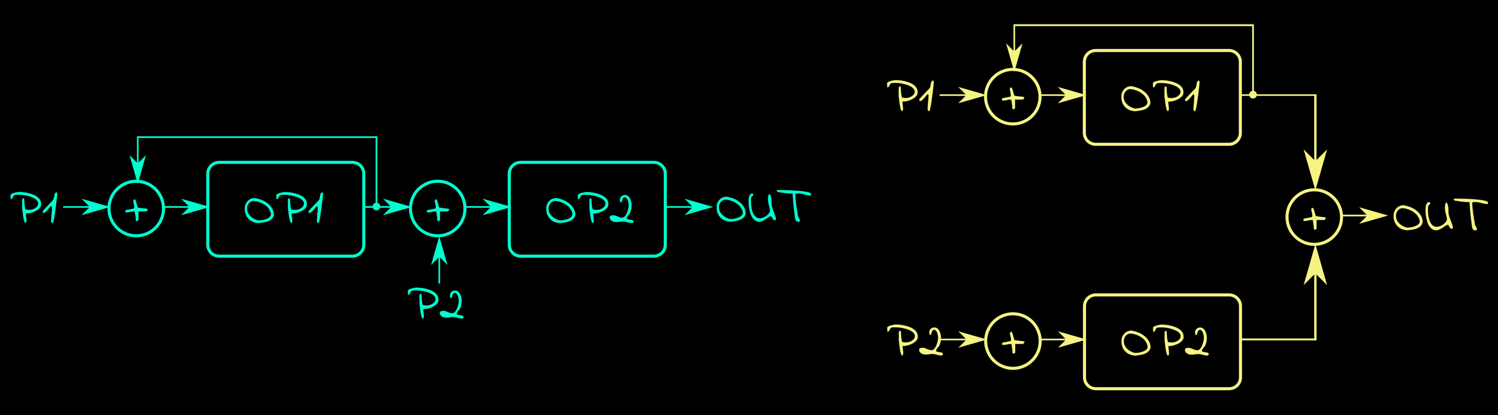 Figure 61: Two Connection options on the ADLIB Soundcard showing how the Operators are combined. |
Digital Samples � PCM Waves, Signed and unsigned
| On modern machines Playing digital sound of speech and other
digital sound is commonplace, but it's actually surprisingly easy
to get almost all these old retro machines to achieve the same
thing.
Actually, the biggest challenge is converting our source file (Which is likely to be a 16 bit signed wave) to the range required by the volume level of our system - often unsigned 4 bit is best as it gives us two samples per source byte, but on a system like the ZX spectrum who's sound can be only 'on' or 'off' we need a 1 bit per sample sound file! For most systems we just need to set the volume level of the channel, but on a small number this alone will make no sound, and we'll need to set the frequency of the channel to some high pitch to form the wave. |
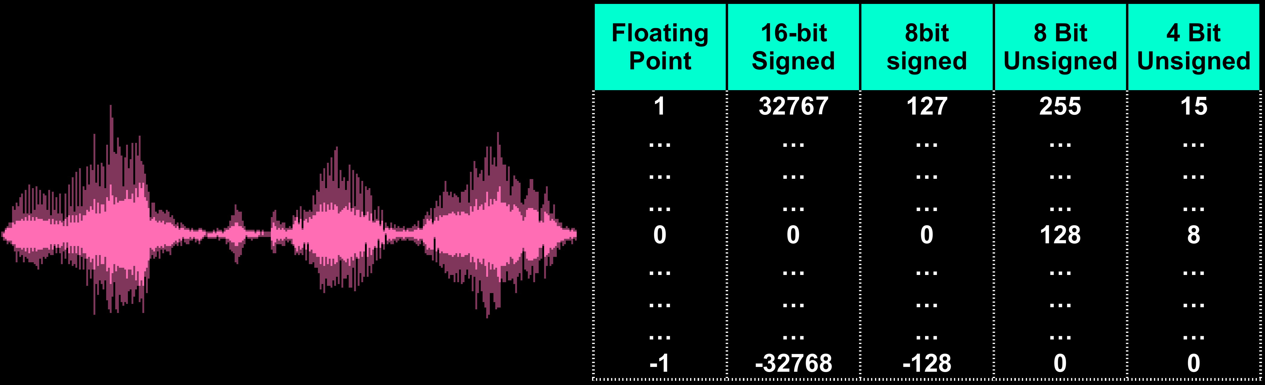 Figure 62: We will need to convert the range of values in our wave file into a range of unsigned values suitable for our classic computers sound system. |
ADPCM � Adaptive Differential Pulse Code Modulation
| 16 bit Sound samples can get pretty big pretty quickly, so some
kind of compression may be desired! Advanced codecs like MP3 would
be great, but these would be too complex for early hardware,
fortunately ADPCM comes to the rescue, offering a 75% reduction in
file size, minimal sound quality loss, and a simple codec!
Suppose we have a 16 bit wave form we want to compress, the wave will go up and down over time. Rather than storing each sample, we could store the 'Difference' between the two samples. In theory we coud reduce this to just 4 bits per per sample, and have a 'look up table' of 16 difference values, using the nearest to attempt to recreate the waveform.
The trouble is, using just 16 possible differences between
samples wouldn't allow for much subtlety, and this is where
'Adaptive Differential PCM' comes in! |
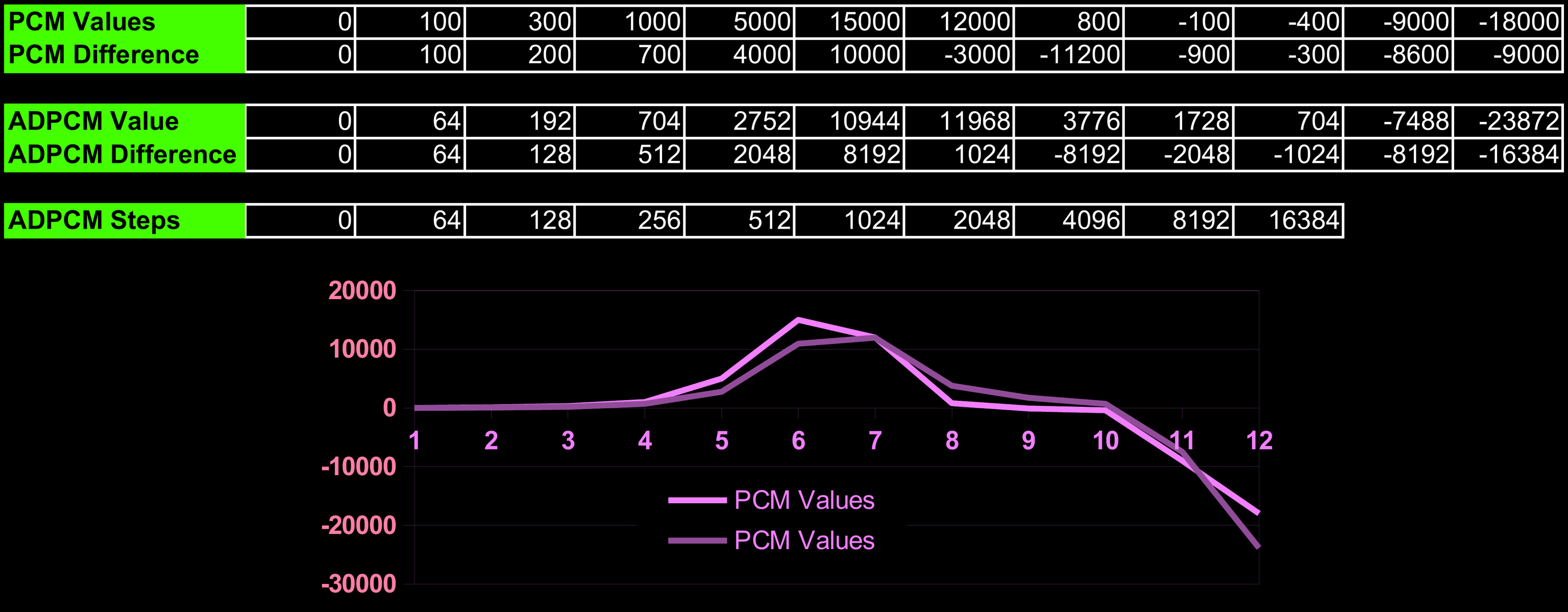 Figure 63: An imaginary ADPCM implementation. Although numerically the stored values look very different, overall the shape of the waveform is not that different. |
I/O Port and Joysticks
It may seem odd to mention Joysticks on the topic of sound, however in some cases the Joysticks are connected to the sound chip, so do not be surprised if you find yourself referring to sound hardware documentation when it comes to reading the Joystick or controlling other devices.
The AY-3-8910 compatible sound chips had a built in I/O port, which was
used for the Joysticks on many systems (Like the CPC,MSX and FM7), and
on the Tandy COCO the DAC that handles sound is also used to read the
analog Joystick.
| Lesson
11 - Other Hardware Terminology There's a few other weird and (somewhat) wonderful terminology we may come across, that it's worth discussing at some point.... and that point is right here! |
|
Analog Joystick
| An Analog Joystick is one that is not just
'On or Off', it will give a range of values depending on the
precise position of the joystick.
If the range was 8 bit, the centre would be a value like 128, full left would be 0 and 'a bit left' would be 100. They give smooth movement, but unfortunately they're often harder to read than a digital joystick, which is only On or Off. This is partially because reading the numeric position is often more complex, and because our imaginary example is unrealistic. An Analog joystick will be slightly 'unreliable', so on a joystick with a centre of 128, you will find it won't actually return to this value every time. The 'centre' would probably be a range of values, and we may consider any value in the range 112-144 to be treated as the 'center', this is known as a Joystick "Dead Zone". |
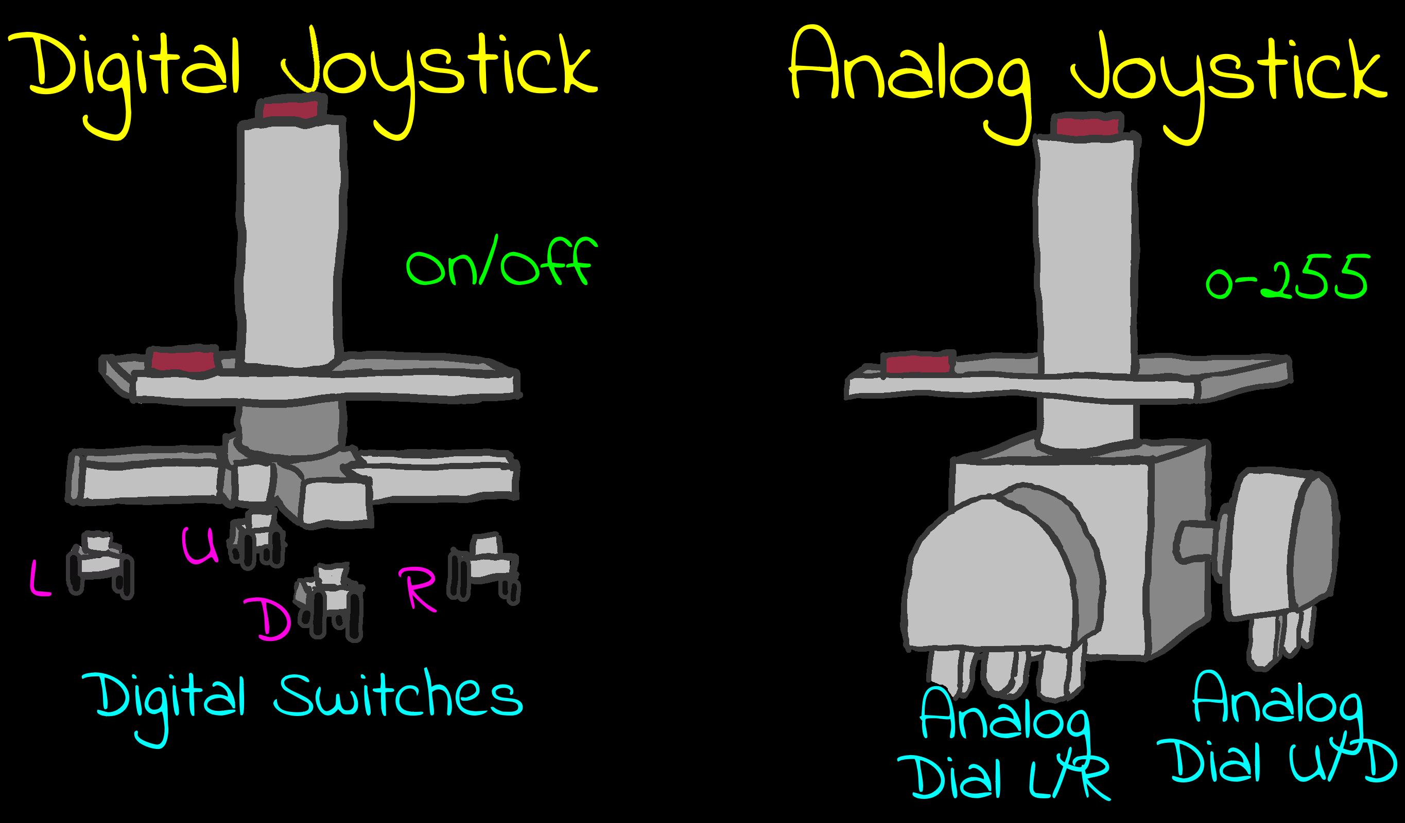 Analog and Digital Joysticks. |
Strobe
A sequence sent to a data port (or single bit of a port) to signal to a device. This is often done to initialize a device and prepare it to start sending data.
For Example: We may strobe a joypad port to tell it to start sending the data for the first of four joypads, subsequent reads will get joypads 2 3 and so on.
DAC / ADC
A Digital to Analog Converter converts a digital signal to an Analog one, for example taking bytes and converting them to sound. ADC is the reverse, taking Analog and converting it to Digital.
Converting between Analog and Digital is needed for sound, non digital joysticks and other such tasks.
Multiplexer
| A device which allows for multiple devices to
share a single line. For Example: On the Tandy COCO, the multiplexer shares the sound DAC between the joystick, speaker and cassette. |
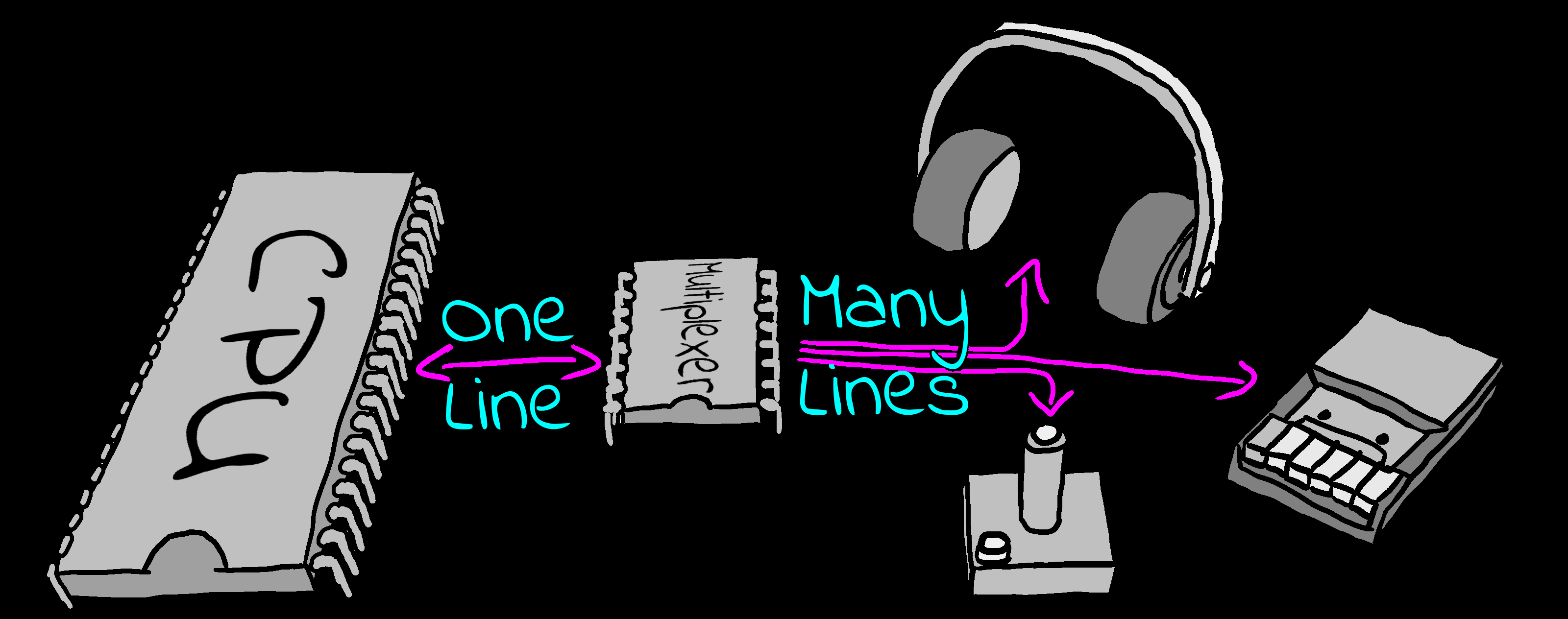 A multiplexer allows multiple devices to connect to one line. |
| View Options |
| Default Dark |
| Simple (Hide this menu) |
| Print Mode (white background) |
| Top Menu |
| ***Main Menu*** |
| Youtube channel |
| Patreon |
| Introduction to Assembly (Basics for absolute beginners) |
| Amazon Affiliate Link |
| AkuSprite Editor |
| ChibiTracker |
| Dec/Bin/Hex/Oct/Ascii Table |
| Alt Tech |
| Archive.org |
| Bitchute |
| Odysee |
| Rumble |
| DailyMotion |
| Please note: I wlll upload more content to these alt platforms based on the views they bring in |
| 68000 Content |
| ***68000 Tutorial List*** |
Learn 68000 Assembly  |
| Hello World Series |
| Platform Specific Series |
| Simple Samples |
| Grime 68000 |
| 68000 Downloads |
| 68000 Cheatsheet |
| Sources.7z |
| DevTools kit |
| 68000 Platforms |
| Amiga 500 |
| Atari ST |
| Neo Geo |
| Sega Genesis / Mega Drive |
| Sinclair QL |
| X68000 (Sharp x68k) |
| 8086 Content |
| Learn 8086 Assembly |
| Platform Specific Series |
| Hello World Series |
| Simple Samples |
| 8086 Downloads |
| 8086 Cheatsheet |
| Sources.7z |
| DevTools kit |
| 8086 Platforms |
| Wonderswan |
| MsDos |
| ARM Content |
| Learn ARM Assembly |
| Learn ARM Thumb Assembly |
| Platform Specific Series |
| Hello World |
| Simple Samples |
| ARM Downloads |
| ARM Cheatsheet |
| Sources.7z |
| DevTools kit |
| ARM Platforms |
| Gameboy Advance |
| Nintendo DS |
| Risc Os |
| Risc-V Content |
| Learn Risc-V Assembly |
| Risc-V Downloads |
| Risc-V Cheatsheet |
| Sources.7z |
| DevTools kit |
| MIPS Content |
| Learn Risc-V Assembly |
| Platform Specific Series |
| Hello World |
| Simple Samples |
| MIPS Downloads |
| MIPS Cheatsheet |
| Sources.7z |
| DevTools kit |
| MIPS Platforms |
| Playstation |
| N64 |
| PDP-11 Content |
| Learn PDP-11 Assembly |
| Platform Specific Series |
| Simple Samples |
| PDP-11 Downloads |
| PDP-11 Cheatsheet |
| Sources.7z |
| DevTools kit |
| PDP-11 Platforms |
| PDP-11 |
| UKNC |
| TMS9900 Content |
| Learn TMS9900 Assembly |
| Platform Specific Series |
| Hello World |
| TMS9900 Downloads |
| TMS9900 Cheatsheet |
| Sources.7z |
| DevTools kit |
| TMS9900 Platforms |
| Ti 99 |
| 6809 Content |
| Learn 6809 Assembly |
| Learn 6309 Assembly |
| Platform Specific Series |
| Hello World Series |
| Simple Samples |
| 6809 Downloads |
| 6809/6309 Cheatsheet |
| Sources.7z |
| DevTools kit |
| 6809 Platforms |
| Dragon 32/Tandy Coco |
| Fujitsu FM7 |
| TRS-80 Coco 3 |
| Vectrex |
| 65816 Content |
| Learn 65816 Assembly |
| Hello World |
| Simple Samples |
| 65816 Downloads |
| 65816 Cheatsheet |
| Sources.7z |
| DevTools kit |
| 65816 Platforms |
| SNES |
| eZ80 Content |
| Learn eZ80 Assembly |
| Platform Specific Series |
| eZ80 Downloads |
| eZ80 Cheatsheet |
| Sources.7z |
| DevTools kit |
| eZ80 Platforms |
| Ti84 PCE |
| IBM370 Content |
| Learn IBM370 Assembly |
| Simple Samples |
| IBM370 Downloads |
| IBM370 Cheatsheet |
| Sources.7z |
| DevTools kit |
| Super-H Content |
| Learn SH2 Assembly |
| Hello World Series |
| Simple Samples |
| SH2 Downloads |
| SH2 Cheatsheet |
| Sources.7z |
| DevTools kit |
| SH2 Platforms |
| 32x |
| Saturn |
| PowerPC Content |
| Learn PowerPC Assembly |
| Hello World Series |
| Simple Samples |
| PowerPC Downloads |
| PowerPC Cheatsheet |
| Sources.7z |
| DevTools kit |
| PowerPC Platforms |
| Gamecube |
| Work in Progress |
| ChibiAndroids |
| Misc bits |
| Ruby programming |
Buy my Assembly programming book
on Amazon in Print or Kindle!


Available worldwide!
Search 'ChibiAkumas' on
your local Amazon website!
Click here for more info!


Buy my Assembly programming book
on Amazon in Print or Kindle!
Available worldwide!
Search 'ChibiAkumas' on
your local Amazon website!
Click here for more info!
Buy my Assembly programming book
on Amazon in Print or Kindle!
Available worldwide!
Search 'ChibiAkumas' on
your local Amazon website!
Click here for more info!
Buy my Assembly programming book
on Amazon in Print or Kindle!
Available worldwide!
Search 'ChibiAkumas' on
your local Amazon website!
Click here for more info!
Buy my Assembly programming book
on Amazon in Print or Kindle!
Available worldwide!
Search 'ChibiAkumas' on
your local Amazon website!
Click here for more info!
Buy my Assembly programming book
on Amazon in Print or Kindle!
Available worldwide!
Search 'ChibiAkumas' on
your local Amazon website!
Click here for more info!
Buy my Assembly programming book
on Amazon in Print or Kindle!
Available worldwide!
Search 'ChibiAkumas' on
your local Amazon website!
Click here for more info!
Buy my Assembly programming book
on Amazon in Print or Kindle!
Available worldwide!
Search 'ChibiAkumas' on
your local Amazon website!
Click here for more info!
Buy my Assembly programming book
on Amazon in Print or Kindle!
Available worldwide!
Search 'ChibiAkumas' on
your local Amazon website!
Click here for more info!
Buy my Assembly programming book
on Amazon in Print or Kindle!
Available worldwide!
Search 'ChibiAkumas' on
your local Amazon website!
Click here for more info!
Buy my Assembly programming book
on Amazon in Print or Kindle!
Available worldwide!
Search 'ChibiAkumas' on
your local Amazon website!
Click here for more info!