

Platform Specific Lessons


Setting up our layers
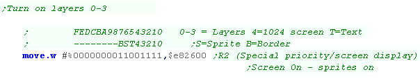
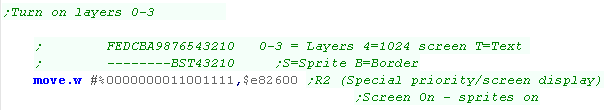
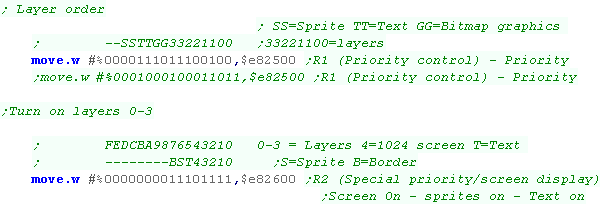
| To make our layers work, we
need to turn them on. We do this with register $E82600 bits 0-3 control the visibility of the 4 bitmap layers |
 |
| We'll also want to decide on the order of our 4 layers. We can set each of the 4 layers to a priority 0-3 |
 |
Drawing to our 4 layers
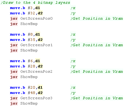
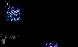
| We're going to show 4 Chibiko's - each on a different layer, then
we'll scroll those layers in different directions. We'll even show a hardware sprite for good measure (The crosshair)... why? because we can! |
 |
| Transferring out bitmap to a layer is easy! we just need to select
the correct VRAM address We'll define 4 versions of 'GetScreenPos' - one for each layer! |
 |
| Here are our 4 calculation routines... each layer has a VRram address $C00000+, separated $80000 apart | 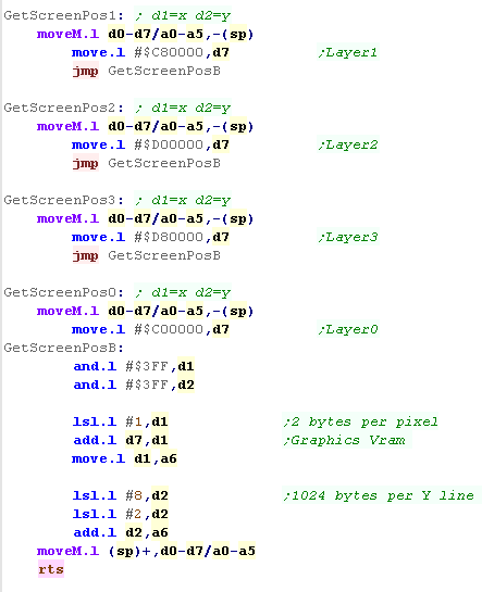 |
Scrolling!
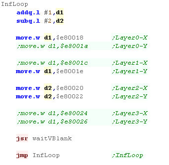
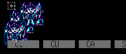
| We can scroll all these layers independently! Although our screen is 256x256, Each layer is 512x512! The scroll positions are defined by registers $E80018+... Each pair of words controls the X and Y scroll for one of the 4 layers |
 |
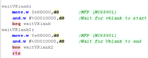
| We've also used a 'WaitVblank' Function to slow down the action. Here it is! We test bit 16 of $e88000 to detect VBLANK. |
 |
Vram Address summary
Here are the addresses you need to write to for each layer!... Don't forget to turn the layers on with $e82600, and set the priority with $e82500!!!
| Layer |
VRAM base |
Scroll-X |
Scroll-Y |
| 0 |
$c00000 | $e80018 | $e8001a |
| 1 |
$c80000 | $e8001c | $e8001e |
| 2 |
$d00000 | $e80020 | $e80022 |
| 3 |
$d80000 | $e80024 | $e80026 |
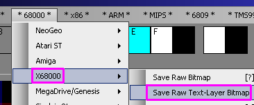
| We've looked at
lots of amazing layers... but the X68000 has more tricks up its
sleeve! Next time we'll check out the 'Text Layer' - a single 16 color layer in a different format! |
 |
The Text Layer VRAM addresses
| Each pixel can be color 0-15... 4 bits per pixel... This data is
split into bitplanes, meaning all the 'bit 0's of the pixels are
stored together, as are bit 1's , 2's and 3's
Bit 0's are at $E00000, Bit 1's are at $E20000 and so on. |
Bitplanes:
|
Palette: $E82200-$E8221E (%GGGGGRRRRRBBBBBT T=Transparent) (Same as Sprite Palette 0)
Scroll-X: $E80014
Scroll-Y: $E80016
Don't forget to turn the layers on with $E82600, and set the priority with $E82500!!!
Preparing the Text Layer.
| Before we can use the Text layer, we need to turn it on. We also need to position it in the layer stack. |
 |
| The system is still drawing to the text layer! If we use the system calls to print a character, it shows to the text layer, Also the Function key display is showing! We need to turn these off! |
  |
| We're going to use 3 functions of the firmware $FF23 DOS commands to Clear the screen, turn off the cursor and the function keys display | 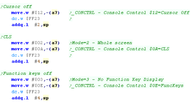 |
| We need to define our palette using address $E82200+ | 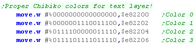 |
Drawing to the screen
| We need to calculate our destination address in VRAM, and transfer the bytes of our graphic to it, but we cannot use the same calculations as for the bitmap screens, as the screen layout is different. | 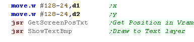 |
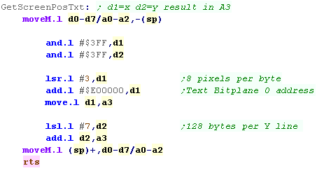
| Each line of the text screen is 1024 pixels, and in a bitplane
there are 8 pixels per byte. Therefore each horizontal line is 128 bytes. Here we calculate the Vram address of the first Bitplane in A3 (Bitplane 0) We'll use this to calculate bitplane 1,2 and 3 addresses later. |
 |
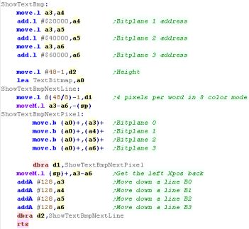
| We need to calculate the addresses for bitplanes 1-3... we do this
by adding $20000,$40000 and $60000, and storing the addresses in
A4-A6 We then transfer the bytes of our source sprite to these bitplanes. Our file is formatted so 4 consecutive bytes are the data for the 4 bitplanes of 8 pixels. This format was used because it's the same format as used by the example on the Amiga and Atari ST. Another alternative would be to have all the data for Bitplane 0 first, then Bitplane 1, then 2 and finally 3... |
 |
| Here's the bitmap! Note... The colors were darker by design to separate the text layer from the bitmaps. |
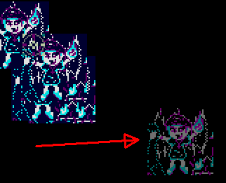 |
| You can export a bitmap in this format with my AkuSprite
Editor, It's free and open source. |
 |
 |
The
X68000 has some impressive graphics, and there's still more to
come! Next time we'll take a look at 256 color, 64k color and high res modes! |
 |
Warning!...
these examples have been only tested on an emulator, and the
author cannot guarantee their effect on real hardware. If you use these on your X68k and they cause the monitor to implode, causing a black hole which sucks your hamster into a dimension of pure evil.... well, you're going to have to clean up the mess yourself! |
The Modes!
There are a wide range of modes available to us!... here's the ones we'll be trying out!
256x256 16 color - 4 layers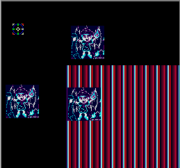 |
256x256 256 color - 2 layers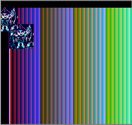 |
256x256 64k color - 1 layer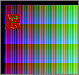 |
512x512 16 color - 4
layers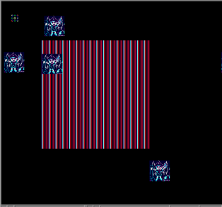 |
768x512 Hires 16 color 1 layer only (1024x1024 layer) 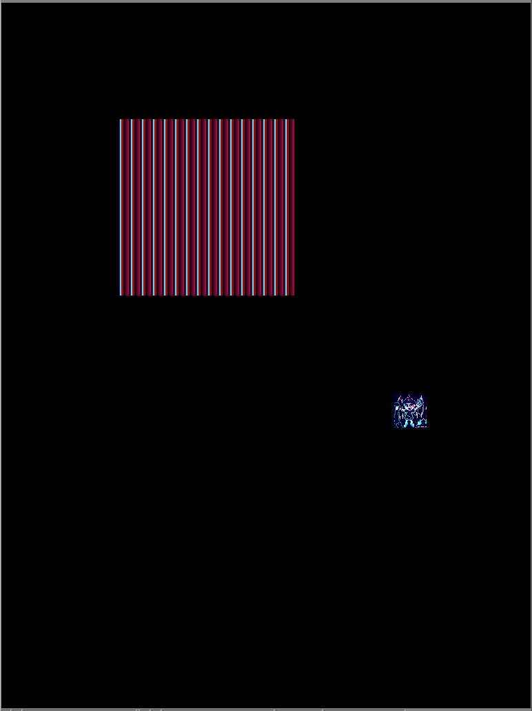 |
| 16 and 256 color
mode use palettes - but 16 bit color mode does not - hence why the
bitmap is messed up! The bits in 64k color mode are in the format %GGGGGRRRRRBBBBBT - 5 bits per channel and one transparent bit!? |
 |
Setting Graphics modes.
Rather than using system calls, We can select a graphics mode by writing
the correct values to registers $e80000-$e8002e
Here are some sample values for a 16 color screen ... you will need to
change the values in the dark section if you want 256 colors.
| High Resolution | Low Resolution | |||||||
| RegNum | 768x512 | 512x512 | 512x256 | 256x256 | 512x512 | 512x256 | 256x256 | Register Purpose |
| E80000 | $89 | $5B | $5B | $2B | $4B | $4B | $25 | R00 Horizontal total |
| E80002 | $0E | $09 | $09 | $04 | $03 | $03 | $01 | R01 Horizontal synchronization end position timing |
| E80004 | $1C | $11 | $11 | $06 | $04 | $05 | $00 | R02 Horizontal display start position |
| E80006 | $7C | $51 | $51 | $26 | $45 | $45 | $20 | R03 Horizontal display end position |
| E80008 | $237 | $237 | $237 | $237 | $103 | $103 | $103 | R04 Vertical total |
| E8000A | $05 | $05 | $05 | $05 | $02 | $02 | $02 | R05 Vertical synchronization end position timing |
| E8000C | $28 | $28 | $28 | $28 | $10 | $10 | $10 | R06 Vertical display start position |
| E8000E | $228 | $228 | $228 | $228 | $100 | $100 | $100 | R07 Vertical display end position |
| E80010 | $1B | $1B | $1B | $1B | $44 | $44 | $24 | R08 External synchronization horizontal adjust: Horizontal position tuning |
| E80028 | $406 |
$405 |
$05 | $01 | $00 | R20 Memory mode/Display mode control |
||
| E82400 | $04 |
$04 | $00 | $00 | $00 | R0 (Screen mode initialization) - Detail | ||
| E82500 | $2E4 | $2E4 | $2E4 | $2E4 | $2E4 | $2E4 | $2E4 | R1 (Priority control) - Priority (Sprites foreground) |
| E82600 | $DF |
$DF | $C1 | $C1 | $C1 | R2 (Special priority/screen display) - Screen On / Sprites On | ||
| EB0808 | $200 | $200 | $200 | $200 | $200 | $200 | $200 | BG Control (Sprites Visible, slow writing) |
| EB080A | $FF | $FF | $FF | $FF | $FF | $25 | Sprite H Total | |
| EB080C | $15 | $15 | $0A | $09 | $09 | $04 | Sprite H Disp | |
| EB080E | $28 | $28 | $28 | $10 | $10 | $10 | Sprite V Disp | |
| EB0810 | $15 | $11 | $10 | $05 | $01 | $00 | Sprite Res %---FVVHH | |
Layers
Whatever screen mode we use, we need to set up our layers
accordingly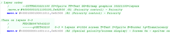 |
Screen Modes
Depending on our screen mode, we need to set the registers accordingly:
256x256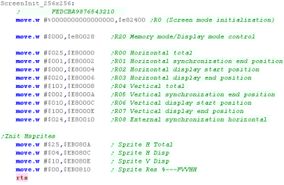 |
512x256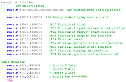 |
512x512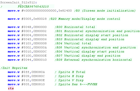 |
Highres Screen Modes
These use the four 512x512 layers as one large 1024x1024 screen - allowing for larger resolutions. this is done by setting bit 2 of $e82400 to 1
512x512 Hires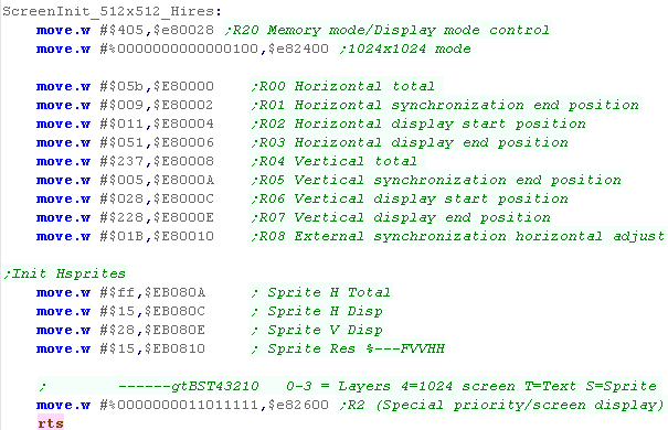 |
768x512 Hires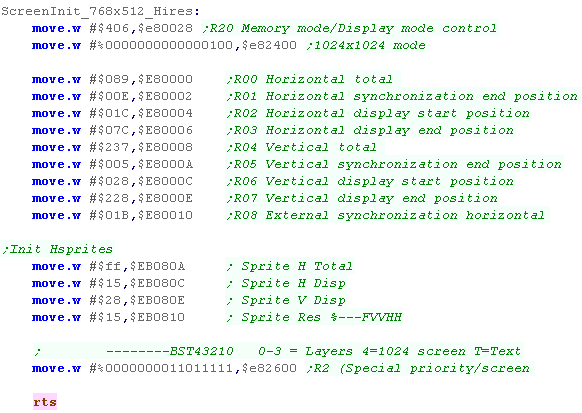 |
Color depth
| We can set the colordepth to 256 color, or 64k color. To do this we need to set bits 0+1 of $e82400, and 16+17 of $e80028 |
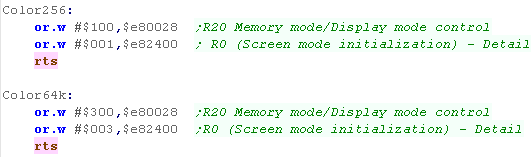 |

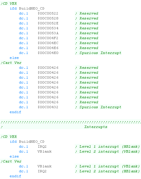
Changes to our rom header
| There's a few trivial changes we need to make to our rom header if
we want to support CD. some of the traps have now changed... and two of the interrupts have swapped round just to keep us on our toes! |
 |
The NeoGeo CD ISO
| A neogeo CD is just a standard ISO. The important thing is the files on it. |
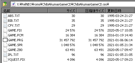 |
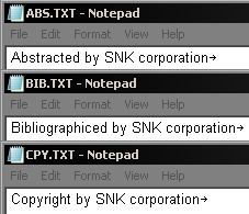
| We need to create 3 files with fixed content... ABS.TXT BIB.TXT
and CPY.TXT - they should have the text shown (They're all in the updated DevTools download) |
 |
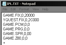
| The most important file is the IPL.TXT! This defines the files
that need to be moved to RAM which make up our game - They also
include the destination addresses. These are the ROM files we would have loaded in our MAME XML. |
 |
IPL.TXT - our game memory and files
Each line of the IPL.TXT contains 3 comma separated entries... there can be up to 32 in total
1. The filename in 8.3 format (Short filename)
2. The Bank number (One digit - typically 0)
3. The Offset in RAM to load the file into - this will affect the
resulting 'Pattern number' of our sprites or Fix layer.
We probably want one PRG, one Z80, and at least one FIX and SPR file - all others are not needed for a simple game.
There are several types of file which will be loaded into different areas of RAM.
| File Type |
Summary |
Details |
| PRG |
Our Program | The main 68000 Program code |
| FIX |
Fix Layer patterns | This is our font and any other graphics for the FIX layer |
| SPR |
Sprite patterns | Graphics for our Sprites - in MAME these we split into two files - on the NEOGEO CD they are a single file - My Akusprite editor has been updated to support this. |
| Z80 |
Z80 sound CPU code | The Z80 program code. |
| OBJ |
RLE compressed Sprites | Compressed Sprites |
| PCM |
ADPCM comressed sound | Compressed digital sounds |
| PAT |
Z80 Patches | Extra code to be loaded into the Z80 ram |
Building our CD file
We can create a valid ISO on the command line with MKISOFS: Here are the parameters we're using -iso-level 1 - Define the CD format we want to use. -pad - Pad the output file to a multiple of 32k -N - omit version number from filenames in ISO -V - set Volume ID The Destination ISO Source files |
| Ok! We have a good ISO, but we need to prep it for MAME which
needs it converting to a CHD We use chdman createcd to convert it... But things get worse! Once again we need to create an XML with a valid hash, but this isn't a sha1 of the file, but the contents of the file.... To calculate the hash we use info -i Which outputs the hash to a text file, then my MakeNeoGeHash program will patch the hash into a template from that exported text file - We now have a valid XML file that the NeoGeo will use! Phew, what a pain! 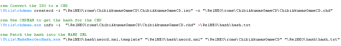 |
Sprites!
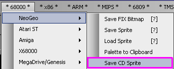
| The way sprites work on the NeoGeo CD is the same, but the file
format is different. Akusprite Editor has been upgraded with a new export option for the correct format. |
 |
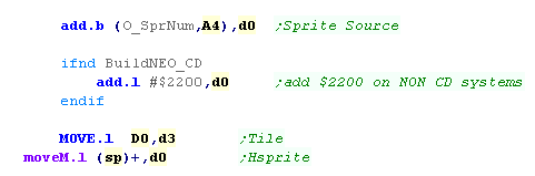
| Depending on the address we load our sprites to, the pattern
numbers may have changed. In Yquest, on the regular NeoGeo Our first Sprite Pattern was #$2200 (due to firmware sprites), but on the NeoGeo CD we start from #0. We will either need to ensure our SPR and FIX data are loaded into the same address in RAM as they were in ROM, or alter our code. |
 |

Mega-CD Rom format
| The Mega CD format uses a 'Boot
Sector' which appears at the very start (Byte 0+) of the ISO
image... the first 16 sectors (32k) of a CD image is usually unused,
so this area is available.
The first $200 bytes ($0000-$01FF) are the header, with the program name and more. The next $584 bytes ($0200-$0783) are a 'Copy Protection block'... this shows the sega logo, and must be correct for the bios of the system you're using... Note: The Japanese version actually only needs a smaller area, but for simplicity it can be padded to $583 bytes with NOP commands approx $200-$7FFF from the start of the CD are copied to genesis RAM $FF0000-$FF7DFF AND $020000-$FF7DFF Execution starts on the Genesis at $FF0000, which will show the Logo, then run your program - Your program would effectively start at $0784 on the CD ($FF0584 in RAM) |
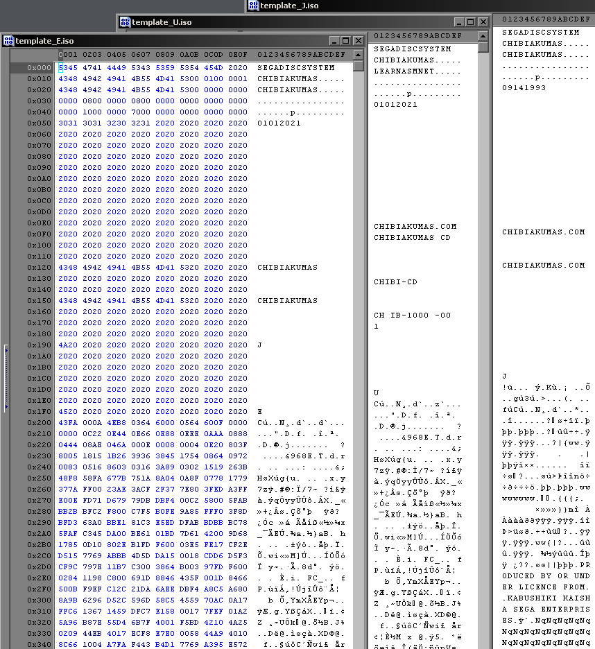 |
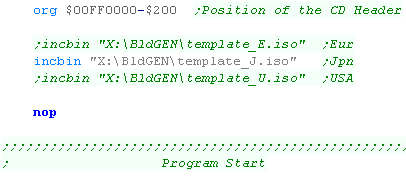
| I've created a 'generic CD header' (Borrowed from some real game
isos!) which we can include at the start of our ASM file. This will ensure the CD has the header that our countries firmware will demand. |
 |
| This will only
work for small programs of a few kilobytes. Really it's just
intended for a 'Bootstrap' If we wanted a bigger program, we'd need to get the CD drive to load it from a file and transfer it to ram, but that's outside of the scope of what we're looking at here. |
 |
Building a CD file
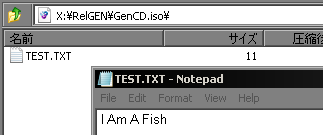
| We're going to build a valid ISO which will have the potential to
store files for future use. The more important thing is the header - which will be our program. |
 |
We compile our ASM file to a binary "\BldGen\Boot.bin"
using VASM (or another 68000 assembler) in the ususal way - but we
now need to insert this as the header to an ISO file. Here are the parameters we're using -iso-level 1 - Define the CD format we want to use. -pad - Pad the output file to a multiple of 32k -G - Specify a 'Generic' boot image -V - set Volume ID The Destination ISO Source files |
|

32 color graphics!
| We've looked at getting a 16 color sprite onscreen, this time we'll upgrade to a 32 color sprite! |  |
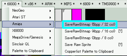
| AkuSprite editor has been upgraded with output options for 5 and 3
bitplane export options! You'll need 5 bitplanes for 32 colors! |
 |
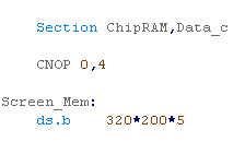
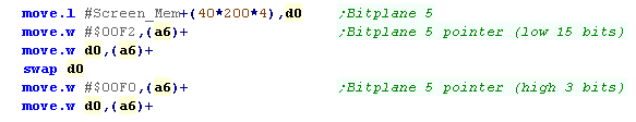
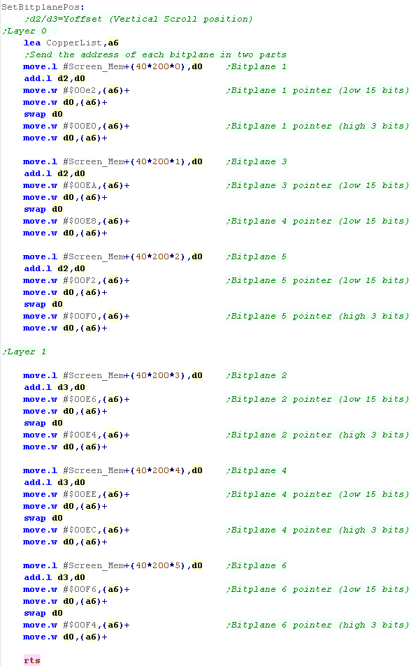
| We need to allocate extra VRAM memory for the 5th bitplane We need to set the copperlist commands to set the fifth bitplane's VRAM address |
  |
| We have to select the screen with BPLCON0 ($dff100) bit 12-14 define the bitdepth - we set these bits to %101 (5) | 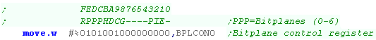 |
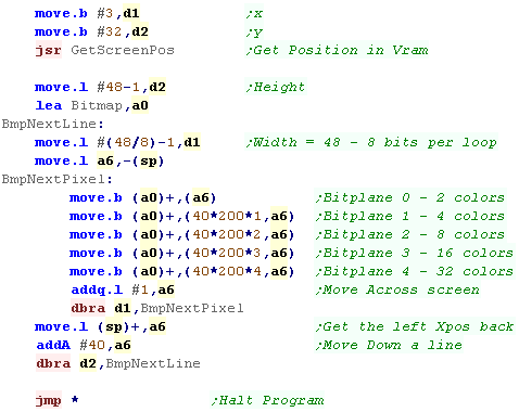
| We also need to 'upgrade' the sprite routine to output the bitmap
data to the extra bitplane (VRAM offset 40*200*4) |
 |
2x 8 color layers
| The Amiga is capable of up to 6 bitplanes... but rather than 64
color these are used to give 2x 8 color Layers (Called Playfields) These have their own VRAM addresses, and can be offset/delayed to effect scrolling Playfield 1 uses Odd bitplanes - and colors 1-7 Playfield 2 uses Even bitplanes - and colors 9-15 |
 |
| We need ram for 6 bitplanes this time! | 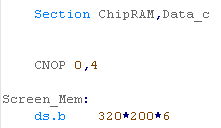 |
| We need to allocate the 6 bitplanes... note we're splitting up the
odd and even bitplanes to make things easier to work with the two
layers. If we add an 'offset' we can effect a hardware scroll.... adding &40 will move down Vertically a single line... adding 2 will move across horizontally one word. |
 |
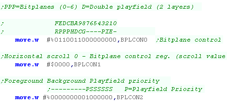
| We set the screen wmode with BPLCON0 ($dff100) bit 12-14 define
the bitdepth - we set these bits to %110 (6)... we also set bit 10
to one... this defines 'Dual playfields' (2 layers) We set the priority of the layers with BPLCON2 ($dff104) Bit 6 can be used to 'swap' the order of the layers |
 |
| We need an alternate sprite drawing to use 3 bitplanes. |
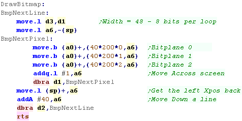 |
| The way we've configured our bitplanes, we can draw to the second layer by adding 40*200*3 to the VRAM destination | 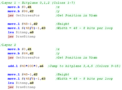 |
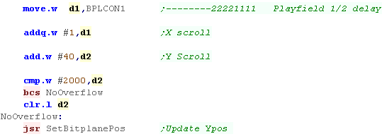
| We can scroll our screen in single pixel increments with the
'Delay function' - defined by BPLCON1 ($dff102) Bits 0-3 set the offset of layer 1 Bits 4-6 set the offset of layer 2. A 'word offset' can be set by changing the VRAM address in the copperlist |
 |
| If you want to use a
large logical screen (with the physical screen showing just a
small square of the logical area) you need to increase the VRAM
allocation. Of course you can allocate more vertical lines without issue, but if you want to allocate horizontal space, you need to set the bytes to 'skip' after each line . This is done with BPL1MOD ($DFF108) and BPL2MOD ($DFF10A)... These default to 0 (no skipped bytes... but setting them to $28 will effectively double the logical screen width. |
|
Interleaved bitplanes
| In the past our screen has been set up with each bitplane in a
separate block... so the VRAM first contaned the data for all the
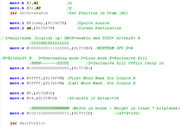
pixels of bitplane 0, then all bitplane 1, followed by 2 and 3. This time, rather than splitting the screen into 'blocks' by bitplane, we'll split by 'lines'... This time the VRAM will contain a line of 40 bytes containing that line pixel's bitplane 0, followed by Bitplane 1,2 and 3... the following data will be the next line. Each line is 320 bytes pixels - 16 colors, so each bitplane will be 40 bytes, and 4 consecutive bitplanes will be 160 bytes. The advantage of this is we can use the BLIT to fill all the bitplanes in one go... so if we want to draw a 48*48 4 bitplane sprite, we just copy an area 192 lines tall to copy all the bitplanes (48*4=192 |
|
|||||||||||||||||||||||||||||||||||||||||||
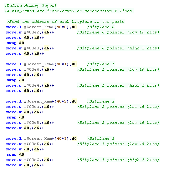
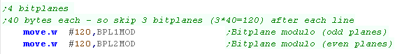
| We don't need to do anything different defining our ram, it's
still defined with "ds.b 320*200*4" But we do need to change our screen definition, we need to set the screen memory pointers to the interleaved addresses, We also need to set BPL1MOD/BPL2MOD to 120, to skip the 3 other bitplanes after each line (160-40=120) |
  |
|||||||||||||||||||||||||||||||||||||||||||
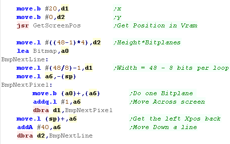
| We can still draw sprites in software, we just need to change our
code. Effectively we draw 4x the height of the sprite, as there are 4 bitplanes vertically interleaved per visible line of pixels. |
 |
|||||||||||||||||||||||||||||||||||||||||||
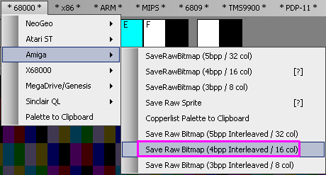
| We'll need our sprite to be in a different format, but AkuSprite
Editor has been upgraded for the Job! There are new Interleaved export options for this example! |
 |
Bring on the BLIT!
The blitter can be used to combine bits from multiple sources and write the result to the destination (in our example VRAM), Remember A and B can be bitshifted, and A can be masked. The MinTerm we use will define the resulting data we write to D. the Sources A,B and C can be bitmap sprites, Masks or the current screen data (for XOR or masked sprites). ABCD must be in CHIP RAM.
Surprisingly Bitshifting does not affect speed, however unsurprisingly the more DMA channels we use, the slower the transfer will be.
Below are the ports we'll need to use to control the blitter... See the Amiga Hardware Manual for more Blitting details
| Name | Address | Function | Bits | Details |
| BLTCON0 | $DFF040 | Blitter control register 0 | SSSSABCD LLLLLLLL | L=miniterms
(Logical op) ABCD=enable dmas SSSS= bitshift A |
| BLTCON1 | $DFF042 | Blitter control register 1 | BBBB---- ---EICDL | B=Bitshift B
D=Descending mode L=Line mode E=Exclusive fill I=Inclusive fill C=fill Carry in |
| BLTAFWM | $DFF044 | Blitter first word mask for source A | MMMMMMMM MMMMMMMM | |
| BLTALWM | $DFF046 | Blitter last word mask for source A | MMMMMMMM MMMMMMMM | |
| BLTCPTH | $DFF048 | Blitter pointer to source C (high 3 bits) | -------- -----HHH | |
| BLTCPTL | $DFF04A | Blitter pointer to source C (low 15 bits) | LLLLLLLL LLLLLLL- | |
| BLTBPTH | $DFF04C | Blitter pointer to source B (high 3 bits) | -------- -----HHH | |
| BLTBPTL | $DFF04E | Blitter pointer to source B (low 15 bits) | LLLLLLLL LLLLLLL- | |
| BLTAPTH | $DFF050 | Blitter pointer to source A (high 3 bits) | -------- -----HHH | |
| BLTAPTL | $DFF052 | Blitter pointer to source A (low 15 bits) | LLLLLLLL LLLLLLL- | |
| BLTDPTH | $DFF054 | Blitter pointer to dest D (high 3 bits) | -------- -----HHH | |
| BLTDPTL | $DFF056 | Blitter pointer to dest D (low 15 bits) | LLLLLLLL LLLLLLL- | |
| BLTSIZE | $DFF058 | Blitter size (window width,height) + START! | HHHHHHHH HHWWWWWW | |
| BLTCON0L | $DFF05A | Blitter control 0, lower 8 bits (minterms) | ||
| BLTSIZV | $DFF05C | Blitter V size (for 15 bit vertical size) | ||
| BLTSIZH | $DFF05E | Blitter H size and start (for 11 bit H size) | ||
| BLTCMOD | $DFF060 | Blitter modulo for source C | MMMMMMMM MMMMMMMM | |
| BLTBMOD | $DFF062 | Blitter modulo for source B | MMMMMMMM MMMMMMMM | |
| BLTAMOD | $DFF064 | Blitter modulo for source A | MMMMMMMM MMMMMMMM | |
| BLTDMOD | $DFF066 | Blitter modulo for destination D | MMMMMMMM MMMMMMMM |
Minterms
'MinTerms' are Logical operations used by BLIT function - these are selected by the bottom 8 bits of BLTCON0 ($DFF040)
In the charts below, ! means NOT (Bits flipped)... in bit logic terms * is effectively AND ... + is effectively OR
| $F0 |
D=A |
| $0F |
D=!A |
| $CC |
D=B |
| $33 |
D=!B |
| $AA |
D=C |
| $55 |
D=!C |
| $A0 |
D=A*C |
$C0 |
D=A*B | $88 |
D=B*C |
| $50 |
D=A*!C |
$30 | D=A*!B | $44 | D=B*!C |
| $0A |
D=!A*C |
$0C | D=!A*B | $22 | D=!B*C |
| $05 |
D=!A*!C | $03 | D=!A*!B | $11 | D=!B*!C |
| $FC |
D=A+B | $EE |
D=B+C | |
| $FA |
D=A+C | $BB |
D=!B+C | |
| $F3 |
D=A+!B | $DD |
D=B+!C | |
| $F5 |
D=A+!C | $77 |
D=B+!C | |
| $CF |
D=!A+B | $FE |
D=A+B+C | |
| $AF |
D=!A+C | $80 |
D=A*B*C | |
| $3F |
D=!A+!B | |||
| $5F |
D=!A+!C |
| $F0 | D=A | PSET | A=Sprite D=ScreenRam |
| $CA |
D=A*B+!A*C |
MASK |
A=SpriteMask B=Sprite C=CurrentScreenRam D=ScreenRam |
| $5A |
D=!A*C+A*!C |
XOR |
A=Sprite C=CurrentScreenRam D=ScreenRam |
The above examples can also be performed in other ways!
Combining Minterms
| Multiple Minterms can be added by ORing... for example:
D=A is $F0 |
Multiple minterms can be multiplied by ANDing... for example:
D=A is $F0 |
 |
'Minterms' are
a boolean algebra thing!... but you only need to know which number
code to use for your blitter. If you're feeling brainy, and want to become a super smarypants, you can learn more about Minterms here... Just be careful your head doesn't explode with all the maths! |
Blitting examples
| In this example we'll use the blitter to show a PSET sprite, an
XOR sprite Bitshift a sprite a few pixels, and show a sprite with transparency mask. We'll also show a CPU drawn sprite (The one with the odd colors) |
 |
| Before we can use the blitter, we need to ensure it's DMA is enabled with bit 6 of DMACON |  |
| First lets try a simple operation PSET! This will transfer our sprite, replacing anything in the background. We'll use Minterm "$F0 D=A" for this ... essentially setting the VRAM (D) to the Sprite (A) in all cases. To start with we need to calculate the VRAM address... we use GetScreenPos to covert an X,Y position into a VRAM pointer (A6) Next we need to set the source for A with BLTAPTH (Our Sprite) and the destination D with BLTDPTH (VRAM from A6) We need to enable the DMA for A+D, and set the Minterm with BLTCON0 We set BLTCON1 to 0 - we don't need any of it's options. If we're pixel shifting we may need to set BLTAFWM/BLTALWM to something strange, but we aren't so we set these to $FFFF After each screen draw we need to skip 34 bytes to get to the next line (40 byte screen - 6 byte wide sprite)... we need to skip nothing for our source sprite... we set BLTAMOD and BLTDMOD accordingly We need to set BLTSIZE to our sprite size... our sprite is 6 bytes wide (3 words) and 48 lines * 4 bitplanes (192 lines) Setting BLTSIZE starts the copy operation! |
 |
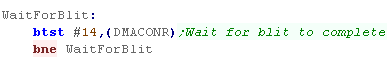
| The blitter works while we're doing other things, so we need to
check if it's done before we send another job, we can do this by
testing bit 14 of DMACONR |
 |
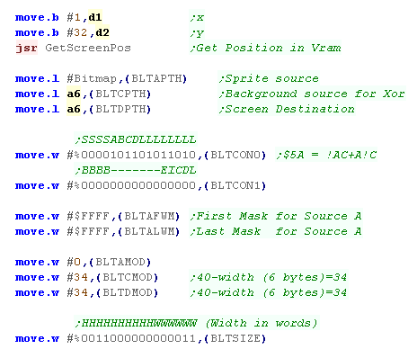
| We can use the blitter with XOR too - to do this we need to use
the current VRAM as a source too (C). We use this with the sprite, inverting the VRAM (C) where the sprite is set (A) and writing back to VRAM (D) The Minterm we're using is "$5A = !AC+A!C" - though there are other ways of getting this effect. |
 |
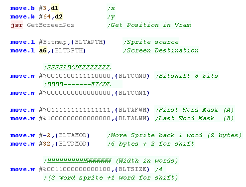
| Our sprites and destination addresses have to be specified in
words (16 pixels), We can get around this by bit shifting source A or B using the top 4 bits of BLTCON0/1 we also need to set an appropriate bit mask for the leftmost and rightmost word of each line of Source A with BLTAFWM/BLTALWM |
 |
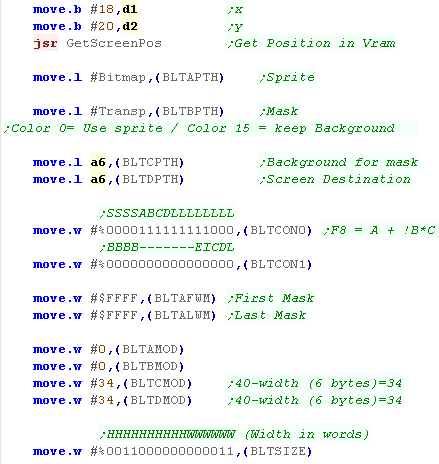
| This time we'll create a 'Transparent' image. This will use a 16 color image as usual, and a 'background mask' which will define the areas of the background which will be left unchanged by the sprite. |
 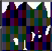 |
| This time we'll need all 3 sources A will be our Color sprite, B will the background mask (also 4 bitplanes) C will be the background VRAM (used for the mask) D will be the screen destination This time the Minterm we'll use is "F8 = A + !B*C " - once again there's many other ways we could achieve the same effect. |
 |
Mouse Reading
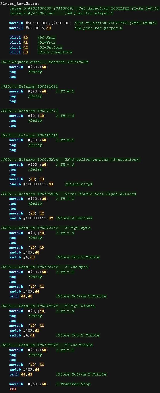
The Genesis mouse can be read from the standard joystick ports.
We need to write #%01100000 to $A10009 for Joy Port 1, or $A1000B for Joy
Port 2
We then send and receive bytes from port $A10003 for Joy Port 1, or
$A10005 for Joy Port 2
Here is the sequence of bytes we send, and bits we receive back:
| Sent Byte | Received Bits | ||||||||
| 7
|
6 | 5 | 4 | 3 | 2 | 1 |
0 |
||
| $60 | 0 | 1 | 1 | 1 | 0 | 0 | 0 | 0 | |
| $20 | 0 | 0 | 1 | 1 | 1 | 0 | 1 | 1 | |
| $00 | 0 | 0 | 0 | 1 | 1 | 1 | 1 | 1 | |
| $20 | 0 | 0 | 1 | 1 | 1 | 1 | 1 | 1 | |
| $00 | 0 | 0 | 0 | 1 | Y
Overflow |
X
Overflow |
Y Sign | X Sign | Overflow flag / Move direction |
| $20 | 0 | 0 | 1 | 0 | Start | Middle | Left | Right | Buttons |
| $00 | 0 | 0 | 0 | 1 | X axis High nibble | X | |||
| $20 | 0 | 0 | 1 | 0 | X axis Low nibble |
X | |||
| $00 | 0 | 0 | 0 | 1 | Y axis High nibble |
Y | |||
| $20 | 0 | 0 | 1 | 0 | Y axis Low nibble |
Y | |||
| $60 | ? | ? | ? | ? | ? | ? | ? | ? | Transfer Stop |
Sample code
| Here is an example program which will send the correct sequence,
and read in the response bits. The example here is set up to read in from Joystick port 2 It will merge the X and Y nibbles, returning the following 4 bytes:
|
 |
Converting to X,Y co-ordinates
| Lets convert the X and Y mouse movements into a 16 bit value we
could use in a game! We'll put a hardware sprite in the mouse position, so we can see what's happening |
 |
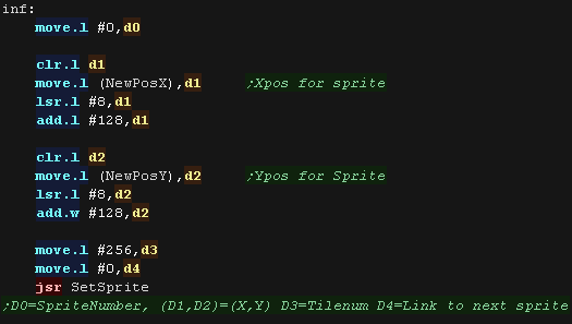
| We're going to put a hardware sprite on screen at the pixel
co-odinate of our sprite. The low byte of the x/y co-ordinate is a 'fractional move' - so we ignore this, For hardware sprites the top left screen pixel is (128,128) |
 |
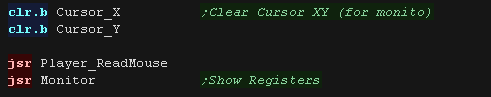
| We run our mouse reading routine... we're showing all the
registers to the screen too - so we can see what's going on. |
 |
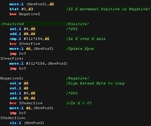
| We check the sign bit of the X axis - and either add or subtract
the X move from the current position. If we're subtracting we sign extend the byte to 32 bits. |
 |
| We do the same for the Y axis - Note, the axis goes the opposite way to the sprite co-ordinates, so we've reversed the way we process the Sign bit. | 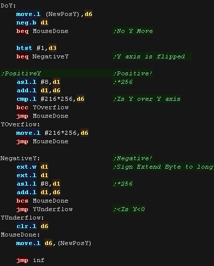 |
|
*** Public Service announcement *** Don't let this
disaster happen to you too! If you leave a mouse connected to port 2, Mega CD game "Mansion of Hidden Souls" will lock up at start up until you remove it!!! Who knows if this is the only game that misbehaves this way, but it caused the author of these tutorials a lot of annoyance, so maybe it's worth bearing in mind! |
ChibiSound PRO!
ChibiSound is the sound driver that handles the particularities of a system, there is typically one driver per system, though the CPC and MSX drivers are essentially identical except for the AY register setting routines.
The original 'ChibiSound' gave us one channel, one Volume bit, six pitch bits, and the ability to turn noise on. Pitches were not matched across systems, so sound 32 won't sound the same on all systems.
The updated 'ChibiSound Pro' gives us all the channels provided by the hardware, 8 volume bits, 16 pitch bits, and the ability to turn noise on. Pitches were not matched across systems, however the 'ChibiOctave' lookup table provides values which ARE matched across all systems.
ChibiSound PRO is essentially a reduced subset of AY functionality, and was designed on the Z80 - it's 'PRO' suffix is a parody of the 'SoundBlaster PRO' - which could only do 8 bit sound so wasn't up to professional standards! (neither is ChibiSound PRO)
ChibiSound PRO provides a standard interface to the underlying hardware, it allows the following features to be set for each channel on the underlying hardware:
| Function |
Register |
Notes: |
| Channel Number (bit 0-6) Noise On/Off (bit 7) |
D3 | Multiple channels can be supported, but on single channel systems
only Channel 0 will be sure to play. If possible Channel 0 will be a center channel, Channels 1+ may be left/right Noise bit turns the noise effect on (1) or off (0) - this can be set on any channel, if the underlying hardware only supports one noise channel, this will be resolved by the driver. |
| Volume | D6 | Set volume of the channel (0-255). Higher numbers are louder. O is off |
| Pitch | D2 | Set the pitch of the channel (0-65535). Higher numbers are higher
pitch. Using DE does not standardize the resulting pitch - however a 'Lookup table' of notes 'ChibiOctave' provides a standardized way of getting the correct DE value to get a pitch correct note on the platform. |
| The
new driver is a big improvement on the old one but doesn't really
deserve the PRO suffix! It's a parody of the early 'Soundblaster Pro' sound cards, which could only do 8 bit digital sound, so weren't really of 'pro spec' either! |
|
Sound Controller - SN76489
We can control the PSG with writes to $C00011 in the format below
| Bits | |||||||||
| Command | Bit Details | 7 | 6 | 5 | 4 | 3 | 2 | 1 | 0 |
| Format Template | L=Latch C=Channel T=Type XXXX=Data | L | C | C | T | D | D | D | D |
| Tone - Command 1/2 | C=Channel L=tone Low data | 1 | C | C | 0 | L | L | L | L |
| Tone - Command 2/2 | H= High tone data (Higher numbers = lower tone) | 0 | - | H | H | H | H | H | H |
| Volume | C=Channel (0-2) V=Volume (15=silent 0=max) | 1 | C | C | 1 | V | V | V | V |
| Noise Channel | (Channel 3) M=Noise mode (1=white) R=Rate (3=use tone 2) | 1 | 1 | 1 | 0 | - | M | R | R |
 |
Chibisound PRO
requires each channel to be capable of noise, but the SN76489
sound chip only has one noise channel. We'll have to track the noise state for each 'virtual noise channel' and update the actual noise channel accordingly |
The ChibiSound Pro driver
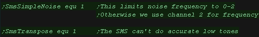
| The BBC/SMS/GEN PSG driver has two options which can be enabled. SmsSimpleNoise: The PSG has two noise options, a noise pitch of 0-2, or a noise pitch set by channel 2 (losing a tone channel). We can enable this option to avoid using tone channel 2, or sacrifice tone functionality for better noise. SmsTranspose: The PSG can't produce accurate low tones, we have two options, use 'off tone' ones, or transpose everything up an octave. |
 |
| We need some ram to keep track of the nose state, and a lookup table for the 3 channels available to the hardware. | 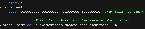 |
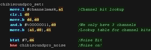
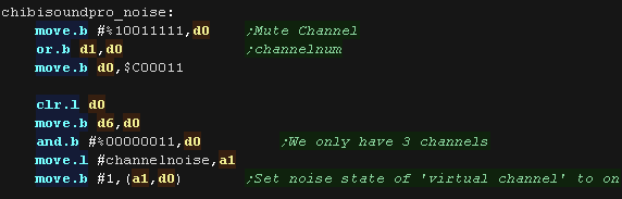
| Our first task is to set D1 to the bitmask for the channel we want
to change. We need to set bits 5-6 of our sound parameters to a channel number. We may be passed a channel 0-127, so we use a 4 bit lookup table to 'map' these to actual channels 0-2 Next we check the noise bit of our passed D6 parameter and branch if needed |
 |
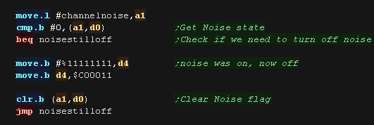
| The noise state may have changed, so we check the previous noise state, and see if we now need to
turn it off. If we do, we do so by setting the volume of channel 3 (noise) to 15 (silent) |
 |
| if noise is on, we silence the tone for that channel and set the
channels noise flag. |
 |
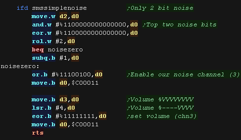
| If we're using simple noise, we need to set the volume of channel
3, and the bottom two bits of the frequency setting - which can only
take a value of 0-2 (3 sets it to use channel 2's frequency setting)
We're done, so we just return. |
 |
| If we're using advanced noise, we need to set the frequency of
channel 2, but the volume of channel 3 We set up the noise setting here - setting the rate to 3. The range of usable noise frequencies on the Genesis seems very narrow, so we have a correction here with D2 to allow usable noise frequencies |
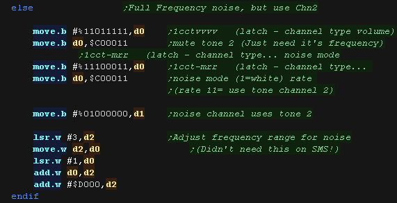 |
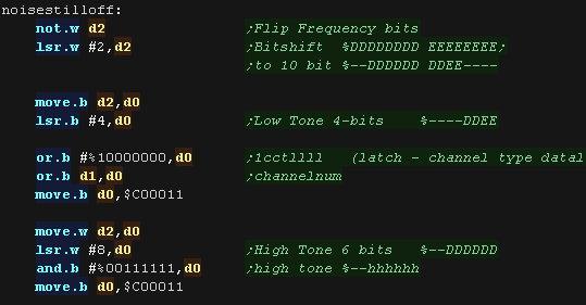
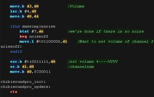
| First we set our frequency. The D2 register passes 16 bits, but we can only use 10, and we need to split those into 6 and 4 and send them to the hardware in two separate parts. |
 |
| We then shift the 8 volume bits into position to pass the 4 bits
to the hardware. If we're not using simple noise, we need to set the frequency of channel 2, but the volume of channel 3 We also flip those bits, as on the hardware 15 is silent, and 0 is loudest. |
 |
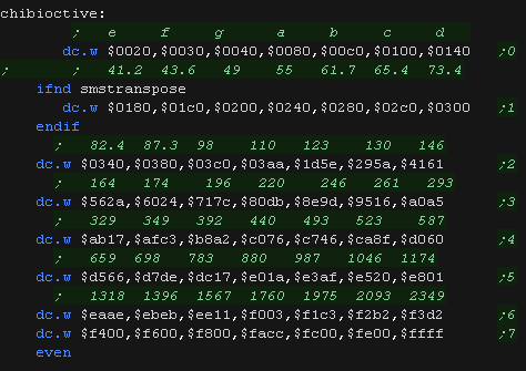
| The ChibiOctave lookup table provides matched notes which can be
loaded into D2 to give consistent tones across all systems. Sharps and flats can be calculated by adding two values and dividing them by two. |
 |
| The PSG is
simple to use, but doesn't offer a large range of tones, so isn't
great for music. Next time we'll look at FM synthesis for better music... but a pain in the arse! |
|
ChibiSound PRO!
ChibiSound is the sound driver that handles the particularities of a system, there is typically one driver per system, though the CPC and MSX drivers are essentially identical except for the AY register setting routines.
The original 'ChibiSound' gave us one channel, one Volume bit, six pitch bits, and the ability to turn noise on. Pitches were not matched across systems, so sound 32 won't sound the same on all systems.
The updated 'ChibiSound Pro' gives us all the channels provided by the hardware, 8 volume bits, 16 pitch bits, and the ability to turn noise on. Pitches were not matched across systems, however the 'ChibiOctave' lookup table provides values which ARE matched across all systems.
ChibiSound PRO is essentially a reduced subset of AY functionality, and was designed on the Z80 - it's 'PRO' suffix is a parody of the 'SoundBlaster PRO' - which could only do 8 bit sound so wasn't up to professional standards! (neither is ChibiSound PRO)
ChibiSound PRO provides a standard interface to the underlying hardware, it allows the following features to be set for each channel on the underlying hardware:
| Function |
Register |
Notes: |
| Channel Number (bit 0-6) Noise On/Off (bit 7) |
D3 | Multiple channels can be supported, but on single channel systems
only Channel 0 will be sure to play. If possible Channel 0 will be a center channel, Channels 1+ may be left/right Noise bit turns the noise effect on (1) or off (0) - this can be set on any channel, if the underlying hardware only supports one noise channel, this will be resolved by the driver. |
| Volume | D6 | Set volume of the channel (0-255). Higher numbers are louder. O is off |
| Pitch | D2 | Set the pitch of the channel (0-65535). Higher numbers are higher
pitch. Using DE does not standardize the resulting pitch - however a 'Lookup table' of notes 'ChibiOctave' provides a standardized way of getting the correct DE value to get a pitch correct note on the platform. |
| The
new driver is a big improvement on the old one but doesn't really
deserve the PRO suffix! It's a parody of the early 'Soundblaster Pro' sound cards, which could only do 8 bit digital sound, so weren't really of 'pro spec' either! |
|
FM Synthesis
The FM sound functionality has a large variety of registers you will need
to control, you can see them all here
|
The author of
these tutorials is a bit of a Thickie!... While todays example
works, it's not really using the FM chip to it's fullest, as the
auther doesn't really know much about FM sound generation! Hopefully we'll find a better author soon, or we'll beat him with sticks until he tries harder! |
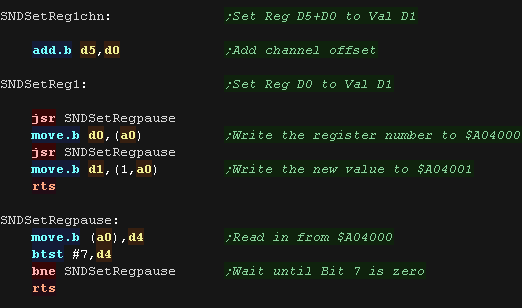
Sound Control functions
| We're going to create a few subroutines to help us out. SNDSetReg1 will set a single register, it will set register D0 on port A0 to value D1 We'll want to specify a sound channel, and a register offset in many cases, SNDSetReg1chn will set register D0+D5 on port A0 to value D1 Before we can write any data to the sound chip, we need to check if it's busy, SNDSetRegpause will read in from the sound port and check if the chip is ready. |
 |
| The Genesis sound channels are split into 2 banks. 1-3 use port $A04000 to select a register and $A04001 to write data. 4-6 use port $A04002 to select a register and $A04003 to write data. Each channel uses a different 'offset' for many of the register numbers. Also we need to use a different 'K-ON' byte (Key on - when the sound starts!) - The bottom three bits define the channel, however these are a bit irregular, as the channels 1,2,3,4,5,6 use K-ON numbers 0,1,2,4,5,6 (effectively %BCC where B=Bank and C=Channel 0-2) |
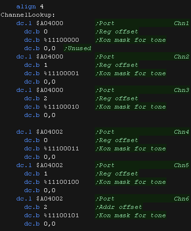 |
| We've created a subroutine ChibiSoundPro_GetChannelAddr to get the parameters for the current channel we want to work with. | 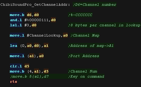 |
Initialization
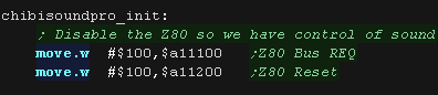
| Todays example only uses the 68000 CPU, but we need to stop the
Z80 from taking over the sound chip We write $100 to $A11100 and $A11200 to lock up the Z80. |
 |
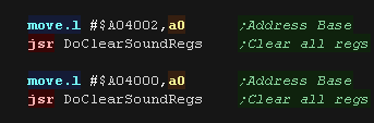
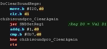
| So we can be in a 'clear' default state, we'll start by setting
all the registers to 0 we use DoClearSoundRegs to do this, and set all regs $20-B7 to zero |
  |
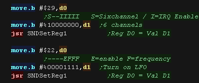
| We need to set some global registers. We set the 'Six channel' bit of $29 (bit 7) so we have access to all the sound channels. We also set up the LFO (Low frequency oscillator) |
 |
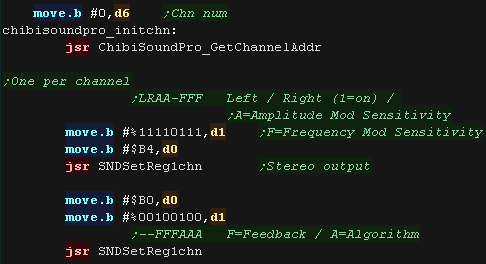
| We need to set up the registers of each channel one at a time. we
use D6 as a loop counter. ChibiSoundPro_GetChannelAddr will set us up to control the channel. We start by setting the stereo level, and set up the feedback (for noise) and algorithm (the sound operator layout) |
 |
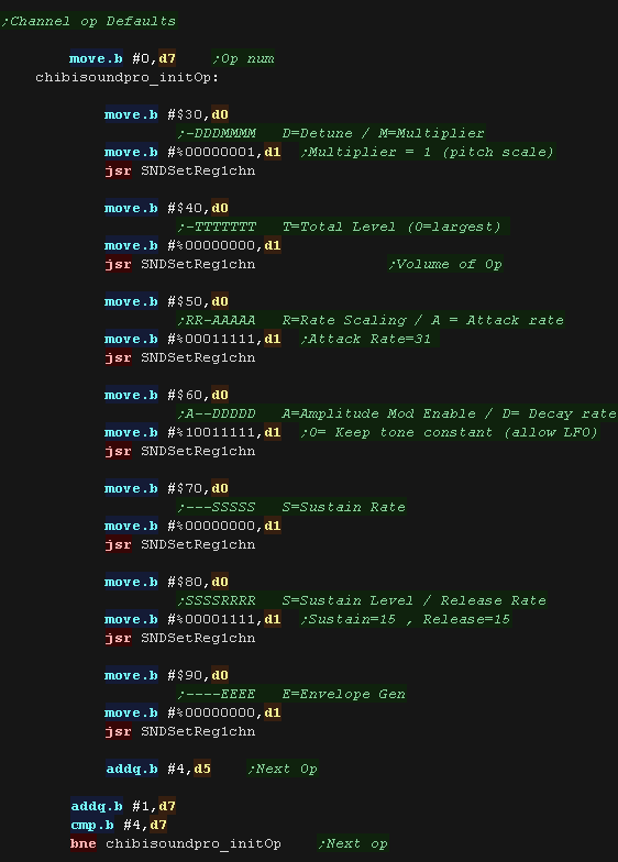
| Each channel has 4 operators... we'll use D7 as an operator count. We'll set up some generic settings for each of these 4 operators We're setting up a basic tone, which starts and stops quickly You can try changing these settings to get different tones! |
 |
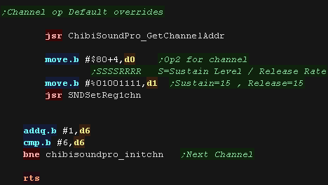
| We override the default sustain we set for OP2, this is to make a
nicer tone. We repeat the settings for the other channels |
 |
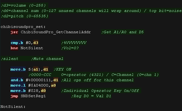
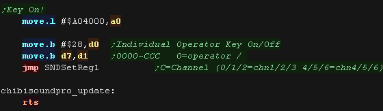
Activating the channel
| When we want to set a channel, we first use ChibiSoundPro_GetChannelAddr
to get the settings for the channel. We next check the volume, and if the sound is to be muted, we change the K-ON command to disable all the operators of the channel - silencing it. |
 |
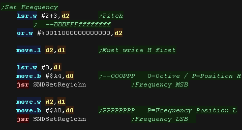
| Next we set the frequency, We use 14 bits to do this - although
the top 3 of these bits are technically a 'bank number' We use registers $A4 and $A0 to do this, we need to write the high byte $A4 first. |
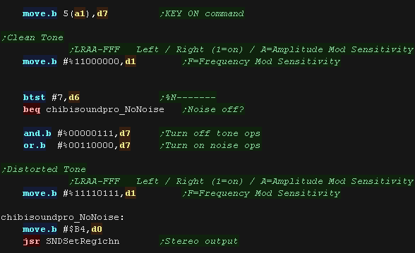
 |
| We're using different operators depending on if we want to make a
tone or a noise - defined by bit 7 of D6 We use 2,3,4 for a tone. We use 1,2 for noise. We also turn on the 'Frequency mod' to distort the tone. |
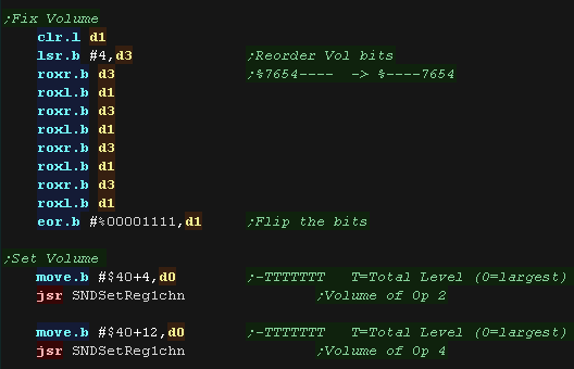
 |
| We need to set the volume, but it's a bit odd on the genesis. 0 is loudest, 1 is much quieter, 3 is extremely quiet, and anything over 15 is pretty much silent! Our loudest setting is 255, We'll flip and re order the bits, then set the volume of the final operator in the chain (Op2 and Op4) |
 |
| We're done. We need to turn on the operators for the channel to
make the sound... we do this with reg B4 (K-ON) |
 |
|
FM Synthesis is a bit of a pain! If you're just looking for simple sound like the odd beep, then the PSG can probably do what you need... take a look here! |
| View Options |
| Default Dark |
| Simple (Hide this menu) |
| Print Mode (white background) |
| Top Menu |
| ***Main Menu*** |
| Youtube channel |
| Patreon |
| Introduction to Assembly (Basics for absolute beginners) |
| Amazon Affiliate Link |
| AkuSprite Editor |
| ChibiTracker |
| Dec/Bin/Hex/Oct/Ascii Table |
| Alt Tech |
| Archive.org |
| Bitchute |
| Odysee |
| Rumble |
| DailyMotion |
| Please note: I wlll upload more content to these alt platforms based on the views they bring in |
| 68000 Content |
| ***68000 Tutorial List*** |
Learn 68000 Assembly  |
| Hello World Series |
| Platform Specific Series |
| Simple Samples |
| Grime 68000 |
| 68000 Downloads |
| 68000 Cheatsheet |
| Sources.7z |
| DevTools kit |
| 68000 Platforms |
| Amiga 500 |
| Atari ST |
| Neo Geo |
| Sega Genesis / Mega Drive |
| Sinclair QL |
| X68000 (Sharp x68k) |
| 8086 Content |
| Learn 8086 Assembly |
| Platform Specific Series |
| Hello World Series |
| Simple Samples |
| 8086 Downloads |
| 8086 Cheatsheet |
| Sources.7z |
| DevTools kit |
| 8086 Platforms |
| Wonderswan |
| MsDos |
| ARM Content |
| Learn ARM Assembly |
| Learn ARM Thumb Assembly |
| Platform Specific Series |
| Hello World |
| Simple Samples |
| ARM Downloads |
| ARM Cheatsheet |
| Sources.7z |
| DevTools kit |
| ARM Platforms |
| Gameboy Advance |
| Nintendo DS |
| Risc Os |
| Risc-V Content |
| Learn Risc-V Assembly |
| Risc-V Downloads |
| Risc-V Cheatsheet |
| Sources.7z |
| DevTools kit |
| MIPS Content |
| Learn Risc-V Assembly |
| Platform Specific Series |
| Hello World |
| Simple Samples |
| MIPS Downloads |
| MIPS Cheatsheet |
| Sources.7z |
| DevTools kit |
| MIPS Platforms |
| Playstation |
| N64 |
| PDP-11 Content |
| Learn PDP-11 Assembly |
| Platform Specific Series |
| Simple Samples |
| PDP-11 Downloads |
| PDP-11 Cheatsheet |
| Sources.7z |
| DevTools kit |
| PDP-11 Platforms |
| PDP-11 |
| UKNC |
| TMS9900 Content |
| Learn TMS9900 Assembly |
| Platform Specific Series |
| Hello World |
| TMS9900 Downloads |
| TMS9900 Cheatsheet |
| Sources.7z |
| DevTools kit |
| TMS9900 Platforms |
| Ti 99 |
| 6809 Content |
| Learn 6809 Assembly |
| Learn 6309 Assembly |
| Platform Specific Series |
| Hello World Series |
| Simple Samples |
| 6809 Downloads |
| 6809/6309 Cheatsheet |
| Sources.7z |
| DevTools kit |
| 6809 Platforms |
| Dragon 32/Tandy Coco |
| Fujitsu FM7 |
| TRS-80 Coco 3 |
| Vectrex |
| 65816 Content |
| Learn 65816 Assembly |
| Hello World |
| Simple Samples |
| 65816 Downloads |
| 65816 Cheatsheet |
| Sources.7z |
| DevTools kit |
| 65816 Platforms |
| SNES |
| eZ80 Content |
| Learn eZ80 Assembly |
| Platform Specific Series |
| eZ80 Downloads |
| eZ80 Cheatsheet |
| Sources.7z |
| DevTools kit |
| eZ80 Platforms |
| Ti84 PCE |
| IBM370 Content |
| Learn IBM370 Assembly |
| Simple Samples |
| IBM370 Downloads |
| IBM370 Cheatsheet |
| Sources.7z |
| DevTools kit |
| Super-H Content |
| Learn SH2 Assembly |
| Hello World Series |
| Simple Samples |
| SH2 Downloads |
| SH2 Cheatsheet |
| Sources.7z |
| DevTools kit |
| SH2 Platforms |
| 32x |
| Saturn |
| PowerPC Content |
| Learn PowerPC Assembly |
| Hello World Series |
| Simple Samples |
| PowerPC Downloads |
| PowerPC Cheatsheet |
| Sources.7z |
| DevTools kit |
| PowerPC Platforms |
| Gamecube |
| Work in Progress |
| ChibiAndroids |
| Misc bits |
| Ruby programming |
Buy my Assembly programming book
on Amazon in Print or Kindle!


Available worldwide!
Search 'ChibiAkumas' on
your local Amazon website!
Click here for more info!


Buy my Assembly programming book
on Amazon in Print or Kindle!
Available worldwide!
Search 'ChibiAkumas' on
your local Amazon website!
Click here for more info!
Buy my Assembly programming book
on Amazon in Print or Kindle!
Available worldwide!
Search 'ChibiAkumas' on
your local Amazon website!
Click here for more info!