

Platform Specific Lessons

ChibiSound PRO!
ChibiSound is the sound driver that handles the particularities of a system, there is typically one driver per system, though the CPC and MSX drivers are essentially identical except for the AY register setting routines.
The original 'ChibiSound' gave us one channel, one Volume bit, six pitch bits, and the ability to turn noise on. Pitches were not matched across systems, so sound 32 won't sound the same on all systems.
The updated 'ChibiSound Pro' gives us all the channels provided by the hardware, 8 volume bits, 16 pitch bits, and the ability to turn noise on. Pitches were not matched across systems, however the 'ChibiOctave' lookup table provides values which ARE matched across all systems.
ChibiSound PRO is essentially a reduced subset of AY functionality, and was designed on the Z80 - it's 'PRO' suffix is a parody of the 'SoundBlaster PRO' - which could only do 8 bit sound so wasn't up to professional standards! (neither is ChibiSound PRO)
ChibiSound PRO provides a standard interface to the underlying hardware, it allows the following features to be set for each channel on the underlying hardware:
| Function |
Register |
Notes: |
| Channel Number (bit 0-6) Noise On/Off (bit 7) |
D3 | Multiple channels can be supported, but on single channel systems
only Channel 0 will be sure to play. If possible Channel 0 will be a center channel, Channels 1+ may be left/right Noise bit turns the noise effect on (1) or off (0) - this can be set on any channel, if the underlying hardware only supports one noise channel, this will be resolved by the driver. |
| Volume | D6 | Set volume of the channel (0-255). Higher numbers are louder. O is off |
| Pitch | D2 | Set the pitch of the channel (0-65535). Higher numbers are higher
pitch. Using DE does not standardize the resulting pitch - however a 'Lookup table' of notes 'ChibiOctave' provides a standardized way of getting the correct DE value to get a pitch correct note on the platform. |
| The
new driver is a big improvement on the old one but doesn't really
deserve the PRO suffix! It's a parody of the early 'Soundblaster Pro' sound cards, which could only do 8 bit digital sound, so weren't really of 'pro spec' either! |
 |
AY Sound Chip
The AY uses a series of 8 bit registers to control the 3 sound channels.
To set a register, we must first select the register number by writing a byte to $FF8800, then send the byte of data to $FF8802
| Register | Meaning | Bit Meaning | Details |
| 0 | Tone Pitch L - Channel A | LLLLLLLL | Lower value = Higher pitch |
| 1 | Tone Pitch H - Channel A | ----HHHH | Lower value = Higher pitch |
| 2 | Tone Pitch L - Channel B | LLLLLLLL | Lower value = Higher pitch |
| 3 | Tone Pitch H - Channel B | ----HHHH | Lower value = Higher pitch |
| 4 | Tone Pitch L - Channel C | LLLLLLLL | Lower value = Higher pitch |
| 5 | Tone Pitch H - Channel C | ----HHHH | Lower value = Higher pitch |
| 6 | Noise Generator | ---NNNNN | Higer = Faster noise |
| 7 | Mixer | --NNNTTT | N=Noise T=Tone (Channel --CBACBA 1=mute 0=normal) |
| 8 | Amplitude - Channel A | ---EVVVV | E=Envelope (1=Enabled) VVVV=Volume |
| 9 | Amplitude - Channel B | ---EVVVV | E=Envelope (1=Enabled) VVVV=Volume |
| 10 | Amplitude - Channel C | ---EVVVV | E=Envelope (1=Enabled) VVVV=Volume |
| 11 | Envelope L (Volume over time) | LLLLLLLL | Lower=Faster Envelope |
| 12 | Envelope H (Volume over time) | HHHHHHHH | Lower=Faster Envelope |
| 13 | Envelope Selection | ----EEEE | Envelope number (See PDF) |
ChibiSound Pro!
| When we're passed a channel number it could be a value from 0-127 We want to map these to the actual channels we have, so we have a lookup table to do this. The Mixer uses 3 bits to enable the tone and noise of the channels, we have a lookup table to get the correct bits. Finally we have a cache in memory of the current AY register values |
 |
| dochannelmask will
load the bits for the selected Channel Mixer into D0+D2, A1 will
point to the Mixer's previous setting in the cache (Reg 7) |
 |
| ayregwrite will do the job of
setting an AY register D0 is the reg number we want to set D1 is the new value for the reg number |
 |
| chibisoundpro_set will set a
channels sound d3 is the channel volume (0-255) d6 is the channel number (0-127)... with bit 7 defining if noise is on d2 is the pitch (0-65535) Our first job is to remap the channel number from 0-127 to 0-2 |
 |
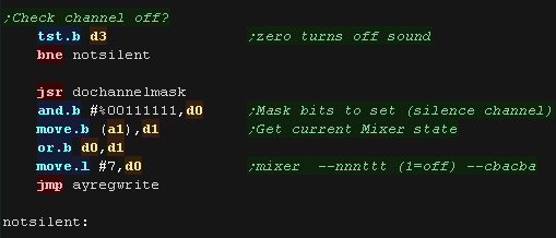
| Next we check the volume - if the channel volume is 0 we need to
mute the channel. We do this by setting the channels bits in the mixer (reg 7) to 1. |
 |
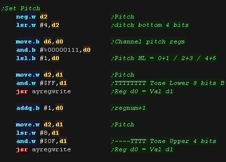
| Next we need to set the pitch! There are two registers that set the pitch, 0/1, 2/3 and 4/5 for channels 0/1/2 d2 has 16 bit value, but the AY only uses 12 bit pitches, so we do some bit shifting! |
 |
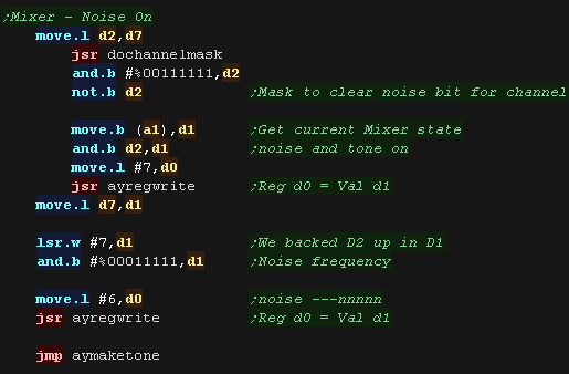
| We need to deal with the noise! If noise is on we need to set the correct bits in the mixer register to 0. We also need to set the noise frequency using reg 6... The noise frequency only uses a 5 bit setting. |
 |
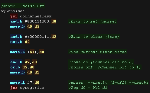
| If the noise is off, we need to disable it by setting the correct
bit in the mixer to 1 we then need to turn the tone on, by setting the correct bit to 0 |
 |
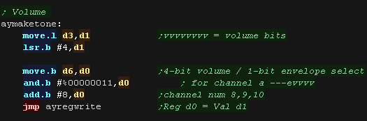
| The last thing to do is set the volume. There is one register per channel, reg 8/9/10 This register takes a 4 bit volume. That's it, we've set all the options for our sound! |
 |
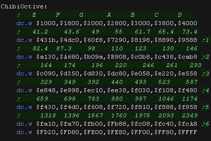
| The ChibiOctave lookup table provides matched notes which can be
loaded into D2 to give consistent tones across all systems. Sharps and flats can be calculated by adding two values and dividing them by two. |
 |
|
Chibisound Pro was
designed around the AY, it was ported from the CPC version! To allow for porting to other hardware, it does not currently take advantage of things like envelopes, as many systems would not support them. |

ChibiSound PRO!
ChibiSound is the sound driver that handles the particularities of a system, there is typically one driver per system, though the CPC and MSX drivers are essentially identical except for the AY register setting routines.
The original 'ChibiSound' gave us one channel, one Volume bit, six pitch bits, and the ability to turn noise on. Pitches were not matched across systems, so sound 32 won't sound the same on all systems.
The updated 'ChibiSound Pro' gives us all the channels provided by the hardware, 8 volume bits, 16 pitch bits, and the ability to turn noise on. Pitches were not matched across systems, however the 'ChibiOctave' lookup table provides values which ARE matched across all systems.
ChibiSound PRO is essentially a reduced subset of AY functionality, and was designed on the Z80 - it's 'PRO' suffix is a parody of the 'SoundBlaster PRO' - which could only do 8 bit sound so wasn't up to professional standards! (neither is ChibiSound PRO)
ChibiSound PRO provides a standard interface to the underlying hardware, it allows the following features to be set for each channel on the underlying hardware:
| Function |
Register |
Notes: |
| Channel Number (bit 0-6) Noise On/Off (bit 7) |
D3 | Multiple channels can be supported, but on single channel systems
only Channel 0 will be sure to play. If possible Channel 0 will be a center channel, Channels 1+ may be left/right Noise bit turns the noise effect on (1) or off (0) - this can be set on any channel, if the underlying hardware only supports one noise channel, this will be resolved by the driver. |
| Volume | D6 | Set volume of the channel (0-255). Higher numbers are louder. O is off |
| Pitch | D2 | Set the pitch of the channel (0-65535). Higher numbers are higher
pitch. Using DE does not standardize the resulting pitch - however a 'Lookup table' of notes 'ChibiOctave' provides a standardized way of getting the correct DE value to get a pitch correct note on the platform. |
| The
new driver is a big improvement on the old one but doesn't really
deserve the PRO suffix! It's a parody of the early 'Soundblaster Pro' sound cards, which could only do 8 bit digital sound, so weren't really of 'pro spec' either! |
|
Amiga Sound Registers
We'll need to use a range of memory mapped registers to control sound. These are mapped from address $DFF096+
Sound on the Amiga is digital, and plays a PCM wave sample, which must be in chip ram, and is driven by a DMA interrupt.
We must provide a valid sample, set up the settings, and start the DMA to make sound.
There are 4 channels in total, two on the left, and two on the right.
| NAME |
|
ADD | R/WD | Chip | Function |
| DMACON | $DFF096 | W | ADP | DMA control write (clear or set) | |
| ADKCON | $DFF09E | W | P | Audio, disk, UART control | |
| AUD0LCH | + | $DFF0A0 | W | A( E ) | Audio channel 0 (L) location (high 3 bits, 5 if ECS) |
| AUD0LCL | + | $DFF0A2 | W | A | Audio channel 0 (L) location (low 15 bits) |
| AUD0LEN | $DFF0A4 | W | P | Audio
channel
0 (L) length (in words) |
|
| AUD0PER | $DFF0A6 | W | P( E ) | Audio channel 0 (L) period | |
| AUD0VOL | $DFF0A8 | W | P | Audio channel 0 (L) volume | |
| AUD0DAT | & | $DFF0AA | W | P | Audio channel 0 (L) data |
| AUD1LCH | + | $DFF0B0 | W | A | Audio channel 1 (R) location (high 3 bits) |
| AUD1LCL | + | $DFF0B2 | W | A | Audio channel 1 (R) location (low 15 bits) |
| AUD1LEN | $DFF0B4 | W | P | Audio channel 1 (R) length (in words) | |
| AUD1PER | $DFF0B6 | W | P | Audio channel 1 (R) period | |
| AUD1VOL | $DFF0B8 | W | P | Audio channel 1 (R) volume | |
| AUD1DAT | & | $DFF0BA | W | P | Audio channel 1 (R) data |
| AUD2LCH | + | $DFF0C0 | W | A | Audio channel 2 (L) location (high 3 bits) |
| AUD2LCL | + | $DFF0C2 | W | A | Audio channel 2 (L) location (low 15 bits) |
| AUD2LEN | $DFF0C4 | W | P | Audio channel 2 (L) length (in words) | |
| AUD2PER | $DFF0C6 | W | P | Audio channel 2 (L) period | |
| AUD2VOL | $DFF0C8 | W | P | Audio channel 2 (L) volume | |
| AUD2DAT | & | $DFF0CA | W | P | Audio channel 2 (L) data |
| AUD3LCH | + | $DFF0D0 | W | A | Audio channel 3 (R) location (high 3 bits) |
| AUD3LCL | + | $DFF0D2 | W | A | Audio channel 3 (R) location (low 15 bits) |
| AUD3LEN | $DFF0D4 | W | P | Audio channel 3 (R) length (in words) | |
| AUD3PER | $DFF0D6 | W | P | Audio channel 3 (R) period | |
| AUD3VOL | $DFF0D8 | W | P | Audio channel 3 (R) volume | |
| AUD3DAT | & | $DFF0DA | W | P | Audio channel 3 (R) data |
ChibiSound Pro!
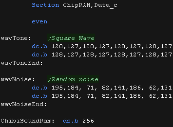
| We need to define some sound samples! These must be in ChipRAM
(the main Amiga memory - not upgrade ram) We need two - a square wave and a distortion sample. ChibisoundRam is used for the music player - we allocate 256 bytes for the players variable. |
 |
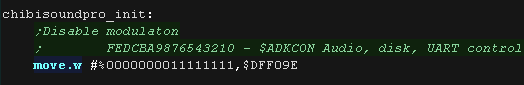
| Our Initialization routine sets things up. There are some sound channel modlulation options, volume and pitch are modulatable we'll disable them using register $DFF09E. Bit 15 defines if we're turning them on or off (0=off), with bit 15 as zero, bits 0-7 are one, which disables these functions |
 |
| We'll update the data in the noise sample each tick to keep the
'nose random' |
 |
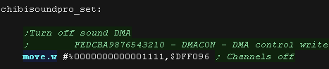
| Before we start messing with the sound registers, we'll turn off
the DMA with $DFF096 Bit 15 defines if we're turning them on or off (0=off), with bit 15 as zero, bits 0-3 are one, which disables the 4 sound channels |
 |
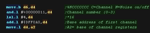
| We need to calculate the base address of the registers for the
channel we want to change. Bits 0-6 of register D6 define the channel number. Each channel has 16 bytes of registers, and the base for the first channel is $DFF0A0 We calculate the base address into A2 |
 |
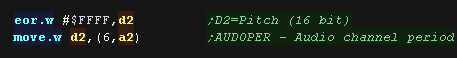
| Next we set the pitch (Period) Our parameter uses a low value for a low pitch, and a high value for a high pitch... but the period is the other way round, so we flip the bits! |
 |
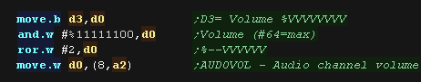
| Now we set the volume... The Amiga needs a value of 0-64, but our
volume byte is 0-255. We bitshift the volume in D3 to create a valid value. |
 |
| We need to select the sample for our tone. If bit 7 of
register D6 is 1 then noise is on. We select the address of the wave sample in A0, and the length in words in d0 |
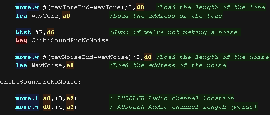 |
| Before we start messing with the sound registers, we'll turn off
the DMA with $DFF096 Bit 15 defines if we're turning them on or off (1=on), with bit 15 as one, bits 0-3 are one, which enables the 4 sound channels, we also need to turn on bit 9, which generally turns on the DMAs |
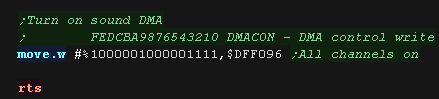 |
| The ChibiOctave lookup table provides matched notes which can be
loaded into D2 to give consistent tones across all systems. Sharps and flats can be calculated by adding two values and dividing them by two. |
 |
 |
If you want to
make different sounds, try changing the wave samples! Also if you want a mono channel, you'll have to use one of the L+R channels to play the same sample at the same time. |
ChibiSound PRO!
ChibiSound is the sound driver that handles the particularities of a system, there is typically one driver per system, though the CPC and MSX drivers are essentially identical except for the AY register setting routines.
The original 'ChibiSound' gave us one channel, one Volume bit, six pitch bits, and the ability to turn noise on. Pitches were not matched across systems, so sound 32 won't sound the same on all systems.
The updated 'ChibiSound Pro' gives us all the channels provided by the hardware, 8 volume bits, 16 pitch bits, and the ability to turn noise on. Pitches were not matched across systems, however the 'ChibiOctave' lookup table provides values which ARE matched across all systems.
ChibiSound PRO is essentially a reduced subset of AY functionality, and was designed on the Z80 - it's 'PRO' suffix is a parody of the 'SoundBlaster PRO' - which could only do 8 bit sound so wasn't up to professional standards! (neither is ChibiSound PRO)
ChibiSound PRO provides a standard interface to the underlying hardware, it allows the following features to be set for each channel on the underlying hardware:
| Function |
Register |
Notes: |
| Channel Number (bit 0-6) Noise On/Off (bit 7) |
D3 | Multiple channels can be supported, but on single channel systems
only Channel 0 will be sure to play. If possible Channel 0 will be a center channel, Channels 1+ may be left/right Noise bit turns the noise effect on (1) or off (0) - this can be set on any channel, if the underlying hardware only supports one noise channel, this will be resolved by the driver. |
| Volume | D6 | Set volume of the channel (0-255). Higher numbers are louder. O is off |
| Pitch | D2 | Set the pitch of the channel (0-65535). Higher numbers are higher
pitch. Using DE does not standardize the resulting pitch - however a 'Lookup table' of notes 'ChibiOctave' provides a standardized way of getting the correct DE value to get a pitch correct note on the platform. |
| The
new driver is a big improvement on the old one but doesn't really
deserve the PRO suffix! It's a parody of the early 'Soundblaster Pro' sound cards, which could only do 8 bit digital sound, so weren't really of 'pro spec' either! |
|
FM Sound - YM2151 Chip
| For full details of the YM2151 can be found in the YM2151
PDF The FM sound chip has 8 channels.... Each channel's sound can be built up with 4 different 'slots'... meaning there are a total of 32 slots... these slots are turned on or off when the sound is triggered Setting a register is easy, we write the register number to $E90001 , then we write the 8 bit value to $E90003 For registers with 32 slots (eg $60 - volume) we can calculate the address of a channels slot with the formula: Address = RegisterBase + 8*ChannelSlot + Channel So if RegisterBase=$60 , ChannelSlot=3 and Channel=7 then we get $60+24+7 |
Setting
a register on the X68000 move.b #$20,$E90001 move.b #%11000000,$E90003 |
YM2151 Registers
The YM2151 is controlled by 255 registers, that are summarized below:
| Address | 7 | 6 | 5 | 4 | 3 | 2 | 1 | 0 | Summary | Bit Meanings |
| $01 | T | T | T | T | T | T | T | T | Test | T=Test |
| $08 | - | S | S | S | S | C | C | C | Key On (Play Sound) | C=Channel S=Slot (C2 �EM2 �EC1 �EM1) |
| $0F | E | - | - | F | F | F | F | F | Noise | E=noise
enable F=Frequency (Noise only on Chn7 Slot32) |
| $10 | C | C | C | C | C | C | C | C | CLKA1 | |
| $11 | - | - | - | - | - | - | C | C | CLKA2 | |
| $12 | C | C | C | C | C | C | C | C | CLKB | |
| $14 | C | - | F | F | I | I | L | L | C=CSM F=F-Reset I=IRQEN L=LOAD | |
| $18 | L | L | L | L | L | L | L | L | LFREQ | |
| $19 | M | M | M | M | M | M | M | M | PMD/AMD | |
| $1B | D | C | - | - | - | - | W | W | D=Disk
state C=CT
(4mhz/8mhz) W=Waveform (0=Saw 1=Square,2=Tri, 3=Noise) |
|
| $20-$27 | L | R | F | F | F | C | C | C | Chn0-7�E/font> | F=Feedback, C=Connection |
| $28-$2F | - | O | O | O | N | N | N | N | Chn0-7�E KeyCode | O=Octave, N=Note |
| $30-$37 | F | F | F | F | F | F | - | - | Chn0-7�EKey Fraction | F=Fraction |
| $38-$3F | - | P | P | P | - | - | A | A | Chn0-7�EPMS / AMS | P=PMS , A=AMS |
| $40-$5F | - | D | D | D | M | M | M | M | Slot1-32. Decay/Mult | D=Decay D1T, M=Mult |
| $60-$7F | - | V | V | V | V | V | V | V | Slot1-32. Volume | V=Volume (TL)
(0=max) |
| $80-$9F | K | K | - | A | A | A | A | A | Slot1-32. Keyscale / Attack | K=Keycale, A=attack |
| $A0-$BF | A | - | - | D | D | D | D | D | Slot1-32. AMS / Decay | A=AMS-EN, D=Decay D1R |
| $C0-$DF | T | T | - | D | D | D | D | D | Slot1-32. DeTune / Decay | T=Detune DT2, D=Decay D2R |
| $E0-$FF | D | D | D | D | R | R | R | R | Slot1-32. Decay / Release | D=Decay D1L, R=Release Rate |
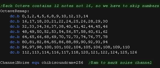
Not all values for NNNN in the Octave in $28-$2F have a different note, the following are useful:
| NNNN Value | 0 |
1 |
2 |
4 |
5 |
6 |
8 |
9 | 10 |
12 |
13 |
14 |
| Note | C# | D | D# | E | F | F# | G | G# | A | A# | B | C |
 |
The author of
these tutorials is a bit of a Thickie!... While todays example
works, it's not really using the FM chip to it's fullest, as the
author doesn't really know much about FM sound generation! Hopefully we'll find a better author soon, or we'll beat him with sticks until he tries harder! |
Sound Control functions
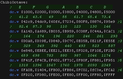
| We're going to create a subroutine to help us out. SetAllSlots will set all 4 slots of a channel to the same value The 4 slots which relate to a channel are 8 registers apart, so we add 8 to d1, and write the value in d0 four times. |
 |
| The octave and note bits of $28-$2F won't take all possible bit
combinations, as the note value can only take certain options. We define a lookup table of valid values here. We can only use the Noise option on channel 7, but chibisound pro could pass it on any channel, so we keep track of 'Virtual noise' with an 8 byte cache. |
 |
| First We start by setting up the waveform for the Frequency and amplitude modulation (PM/AM) | 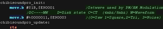 |
Activating the channel
| We only have 7 channels, so we mask the bottom 3 bits of the channel number and store it in d4 - this will be our 'register offset' for changing the setting of our channel | 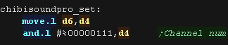 |
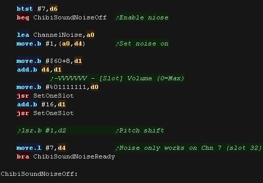
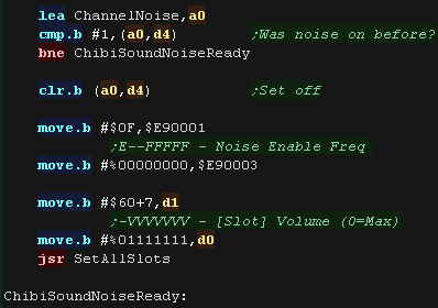
| If noise is on we set the flag for this channel in 'ChannelNoise' We then mute the current channel - we redirect all noise effects to channel 7 as it's the only channel which can use the noise frequency. |
 |
| If the channel noise was on before, we now need to stop channel 7,
and mark the flag off now. |
 |
| Next We check if we need to silence the channel. If we do, we set Key-Off, buy setting all the slot bits to zero for this channel in register $08 |
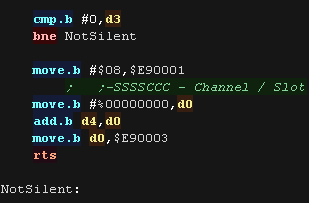 |
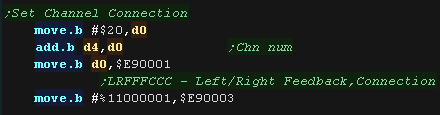
| We need to configure the 'connection' of how the sound is built
from the slots, we're using Connection 1 |
 |
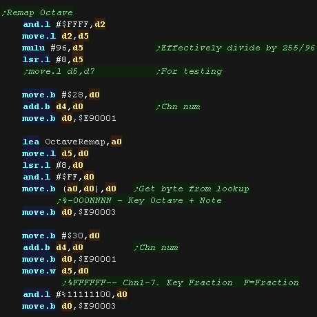
| We need to set the octave and key, but we can't really use our
pitch directly in d2, so we convert it with the OctaveRemap table we set the high and low parts of the pitch with registers $28 and $30 |
 |
| We need to set the attack and delay for the slots. We don't change these values whatever our pitch and note type. |
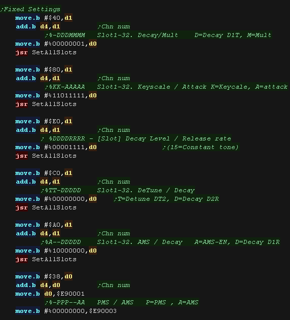 |
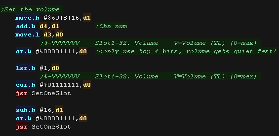
| We set the volume of the endpoints of our connector. A value of zero is loudest, we reduce the volume of slot 2 to alter the sound. |
 |
| It's time to start our channel - we use K-On to enable the slots for this channel | 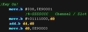 |
| If we need to use noise we set the settings of register $0F This takes a 5 bit frequency setting, and we enable noise with bit 7 |
 |
|
FM Synthesis is a bit of a pain! If you're just looking for simple sound like the odd beep, then the PSG can probably do what you need... take a look here! |
ChibiSound PRO!
ChibiSound is the sound driver that handles the particularities of a system, there is typically one driver per system, though the CPC and MSX drivers are essentially identical except for the AY register setting routines.
The original 'ChibiSound' gave us one channel, one Volume bit, six pitch bits, and the ability to turn noise on. Pitches were not matched across systems, so sound 32 won't sound the same on all systems.
The updated 'ChibiSound Pro' gives us all the channels provided by the hardware, 8 volume bits, 16 pitch bits, and the ability to turn noise on. Pitches were not matched across systems, however the 'ChibiOctave' lookup table provides values which ARE matched across all systems.
ChibiSound PRO is essentially a reduced subset of AY functionality, and was designed on the Z80 - it's 'PRO' suffix is a parody of the 'SoundBlaster PRO' - which could only do 8 bit sound so wasn't up to professional standards! (neither is ChibiSound PRO)
ChibiSound PRO provides a standard interface to the underlying hardware, it allows the following features to be set for each channel on the underlying hardware:
| Function |
Register |
Notes: |
| Channel Number (bit 0-6) Noise On/Off (bit 7) |
D3 | Multiple channels can be supported, but on single channel systems
only Channel 0 will be sure to play. If possible Channel 0 will be a center channel, Channels 1+ may be left/right Noise bit turns the noise effect on (1) or off (0) - this can be set on any channel, if the underlying hardware only supports one noise channel, this will be resolved by the driver. |
| Volume | D6 | Set volume of the channel (0-255). Higher numbers are louder. O is off |
| Pitch | D2 | Set the pitch of the channel (0-65535). Higher numbers are higher
pitch. Using DE does not standardize the resulting pitch - however a 'Lookup table' of notes 'ChibiOctave' provides a standardized way of getting the correct DE value to get a pitch correct note on the platform. |
| The
new driver is a big improvement on the old one but doesn't really
deserve the PRO suffix! It's a parody of the early 'Soundblaster Pro' sound cards, which could only do 8 bit digital sound, so weren't really of 'pro spec' either! |
|
QL Sound Commands
| Sound commands have to be passed via
the Bios, using the same kind of commands as with the keyboard. You need to adjust the Pitch settings to change the sound, and you can change the randomness bits to make the sound distorted, It seems it's not possible to change the volume! |
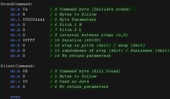
lea SoundCommand,a3 ; These three lines move.b #$11,d0 ; Stop the note trap #1 SoundCommand: dc.b $A ; Command dc.b 8 ; Bytes to follow dc.l $0000aaaa ; Byte Parameters dc.b 0 ; Pitch 1 dc.b 0 ; Pitch 2 dc.w 0 ; interval between steps (0,0), dc.w $FFFF ; Duration (65535) dc.b 0 ; step in pitch (4bit) / wrap (4bit) dc.b 0 ; randomness of step (4bit) / fuzziness (4bit) dc.b 1 ; No return parameters |
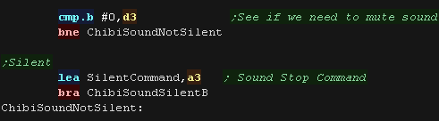
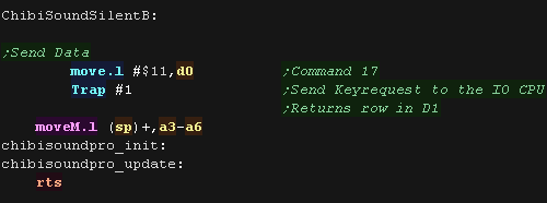
| The sound chip has a special 'silent' command - it's similar to the sound command, but with fewer parameters! |
lea SilentCommand,a3 ; These three lines move.b #$11,d0 ; Stop the note trap #1 SilentCommand: dc.b $B ; Command byte dc.b 0 ;Bytes to follow dc.l $0 ; Send no data dc.b 1 ; No return parameters |
Trap #1 - MT.IPCOM
| Parameter | Byte Offset | Size (bytes) | Bits | Purpose | Example (sound on) |
Example (sound off) |
| 0 | 1 | %----CCCC | Command Byte $0A=Sound on / $0B=Sound off | $A | $B | |
| 1 | 1 | %LLLLLLLL | L=Length of command in bytes | $8 | 0 | |
| 2 | 4 |
%llLLllLLllLLllLL %llLLllLLllLLllLL |
LL/ll=Length of parameters (%01/11=nothing %10=8 bits %00=4 Least significant bits) |
$0000AAAA | 0 | |
| 1 | 6 | 1 |
%HHHHHHHH | Pitch H | 0 | 1 |
| 2 | 7 | 1 |
%LLLLLLLL | Pitch L | 0 | |
| 3+4 | 8 | 2 |
%IIIIIIIIIIIIIIII | Interval between steps | 0 | |
| 5+6 | 10 | 2 |
%DDDDDDDDDDDDDDDD | Duration | $FFFF | |
| 7 | 12 | 1 |
%SSSSWWWW | Step / Wrap | 0 | |
| 8 | 13 | 1 |
%RRRR/FFFF | Randomness / Fuzziness | 0 | |
| 14 | 1 |
%------LL | L=Reply length (%01/11=nothing %10=8 bits %00=4 Least significant bits) |
1 |
Sound Control functions
| We need to send some byte sequences to Trap #1 to control the
sound. We'll define some template bytes to do this, and patch in pitch and noise parameters as required |
 |
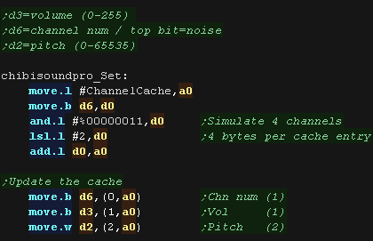
| We can only play one sound at a time, but ChibiTracks want's at
least 3! We'll simulate 4 virtual channels, keeping their settings in a cache, and play only the loudest one. |
 |
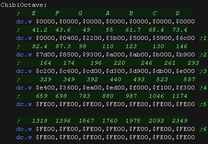
| The ChibiOctave lookup table provides matched notes which can be
loaded into D2 to give consistent tones across all systems. Sharps and flats can be calculated by adding two values and dividing them by two. |
 |
Setting the sound channel
| When we're asked to change the settings of a channel we first
store it's settings in the virtual channel cache. Each channel takes 4 bytes. |
 |
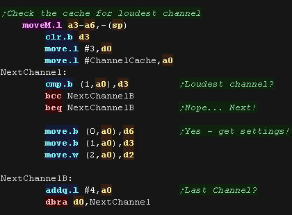
| We can only play one sound at a time, so we select the loudest of
the 4 virtual channels to actually play. |
 |
| Next we check the volume level we need to set. If it's Zero we silence the sound |
 |
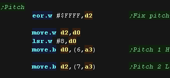
| Next we set the two pitch bytes. We need a high number to be a high pitch, so we EOR the bits to flip them. |
 |
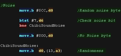
| If we set the 'Randomness' to 0 we'll have a clean tone, if we set
it to $CC we'll create a distorted one. We select this based on bit 7 of D6 |
 |
| We send the data to Trap $11 a3 is points to the data to configure the sound |
 |
| You may have
noticed that we didn't set the volume, that's because on the QL
you can't!... so we, er didn't! The QL was more intended as a business machine than for gaming, so I guess sound was a bit of an afterthought... oh well! |
|

ChibiSound PRO!
ChibiSound is the sound driver that handles the particularities of a system, there is typically one driver per system, though the CPC and MSX drivers are essentially identical except for the AY register setting routines.
The original 'ChibiSound' gave us one channel, one Volume bit, six pitch bits, and the ability to turn noise on. Pitches were not matched across systems, so sound 32 won't sound the same on all systems.
The updated 'ChibiSound Pro' gives us all the channels provided by the hardware, 8 volume bits, 16 pitch bits, and the ability to turn noise on. Pitches were not matched across systems, however the 'ChibiOctave' lookup table provides values which ARE matched across all systems.
ChibiSound PRO is essentially a reduced subset of AY functionality, and was designed on the Z80 - it's 'PRO' suffix is a parody of the 'SoundBlaster PRO' - which could only do 8 bit sound so wasn't up to professional standards! (neither is ChibiSound PRO)
ChibiSound PRO provides a standard interface to the underlying hardware, it allows the following features to be set for each channel on the underlying hardware:
| Function |
Register |
Notes: |
| Channel Number (bit 0-6) Noise On/Off (bit 7) |
D3 | Multiple channels can be supported, but on single channel systems
only Channel 0 will be sure to play. If possible Channel 0 will be a center channel, Channels 1+ may be left/right Noise bit turns the noise effect on (1) or off (0) - this can be set on any channel, if the underlying hardware only supports one noise channel, this will be resolved by the driver. |
| Volume | D6 | Set volume of the channel (0-255). Higher numbers are louder. O is off |
| Pitch | D2 | Set the pitch of the channel (0-65535). Higher numbers are higher
pitch. Using DE does not standardize the resulting pitch - however a 'Lookup table' of notes 'ChibiOctave' provides a standardized way of getting the correct DE value to get a pitch correct note on the platform. |
| The
new driver is a big improvement on the old one but doesn't really
deserve the PRO suffix! It's a parody of the early 'Soundblaster Pro' sound cards, which could only do 8 bit digital sound, so weren't really of 'pro spec' either! |
|
AY Sound Chip
The AY uses a series of 8 bit registers to control the 3 sound channels.
To set a register, we must first select the register number by writing a byte to $FF8800, then send the byte of data to $FF8802
| Register | Meaning | Bit Meaning | Details |
| 0 | Tone Pitch L - Channel A | LLLLLLLL | Lower value = Higher pitch |
| 1 | Tone Pitch H - Channel A | ----HHHH | Lower value = Higher pitch |
| 2 | Tone Pitch L - Channel B | LLLLLLLL | Lower value = Higher pitch |
| 3 | Tone Pitch H - Channel B | ----HHHH | Lower value = Higher pitch |
| 4 | Tone Pitch L - Channel C | LLLLLLLL | Lower value = Higher pitch |
| 5 | Tone Pitch H - Channel C | ----HHHH | Lower value = Higher pitch |
| 6 | Noise Generator | ---NNNNN | Higer = Faster noise |
| 7 | Mixer | --NNNTTT | N=Noise T=Tone (Channel --CBACBA 1=mute 0=normal) |
| 8 | Amplitude - Channel A | ---EVVVV | E=Envelope (1=Enabled) VVVV=Volume |
| 9 | Amplitude - Channel B | ---EVVVV | E=Envelope (1=Enabled) VVVV=Volume |
| 10 | Amplitude - Channel C | ---EVVVV | E=Envelope (1=Enabled) VVVV=Volume |
| 11 | Envelope L (Volume over time) | LLLLLLLL | Lower=Faster Envelope |
| 12 | Envelope H (Volume over time) | HHHHHHHH | Lower=Faster Envelope |
| 13 | Envelope Selection | ----EEEE | Envelope number (See PDF) |
Sending data - Z80 Side
| We have to send data to the Z80 one byte at a time.... But we need
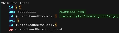
4 bytes to control chibisound pro! We'll send these as 8 nibbles, with the high byte of the nibbles sent as a 'command', and the low nibble as the 'data'. We'll also keep compatibility with the old '1 byte chibisound'. Here are the formats we use: %1001---- Chibisiound PRO Initialize %1010---- ChibiSound PRO Data Nibble %1011---- ChibiSound PRO Process data Here are the Classic Chibisound formats: %1000---- = Classic 1st nibble %1100---- = Classic 2nd nibble + exec |
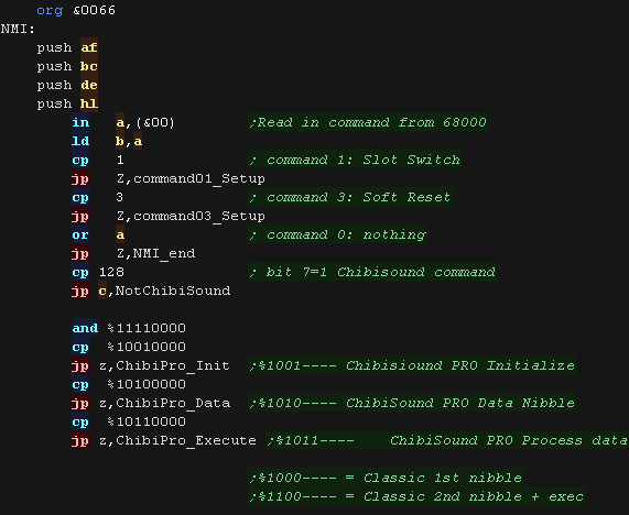 |
| ChibiPro_Init will reset the byte pos, announcing an new sequence
has been sent. The bottom nibble is a 'Version number' 0=ChibiSound PRO, 1+ are reserved for future sound drivers (ChibiSound AWE32!?!?) |
 |
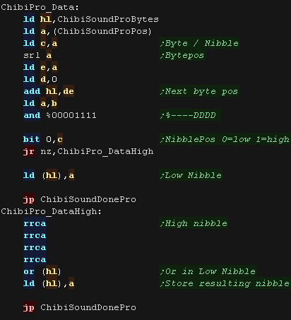
| We send the bytes in two nibble parts. We send the Low nibble, then the High nibble The receiving code combines these together, using ChibiSoundProPos as a 'nibble position' |
 |
| The execute command also reserves the low nibble as a 'Version
number' for the execute command. it should be 0 for ChibiSound Pro. DE is loaded from the first two bytes that were sent. HL is loaded from the second two bytes that were sent. |
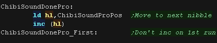 |
| After each byte is received, we INC the ChibiSoundProPos destination nibble. | 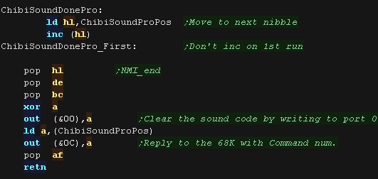 |
Sending data - 68000 Side
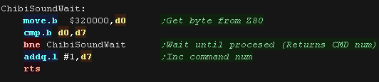
| When we send data to the Z80, the new driver will confirm receipt
by returning ChibiSoundProPos on port $320000/&0C we need to execute ChibiSoundWait after each byte command is sent. |
 |
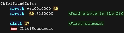
| The INIT command sends the Init sequence to the Z80, telling it to
reset for a new sequence of bytes. |
 |
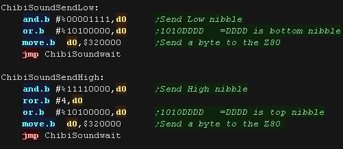
| SendLow and SendHigh send the low and high nibbles of a byte. the Low nibble needs to go first the High nibble goes second. then another bytes Low nibble can be sent and so on. |
 |
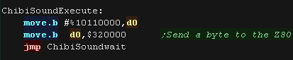
| Once all our nibbles are sent, we perform the Execute command to
process the byte stream. |
 |
ChibiSound PRO - 68000 Side
| The chibisoundpro_set routine will transfer the 4 parameter bytes
to the z80 d3=volume (0-255) d6=channel num (0-127 unused channels will wrap around) / top bit=noise d2=pitch (0-65535) |
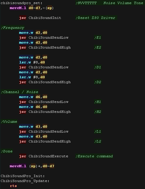 |
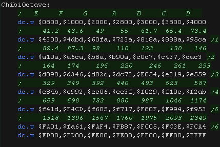
| ChibiSound PRO provides a lookup table of the correct frequencies
in the octave. |
 |
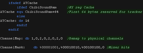
ChibiSound PRO - Z80 Side
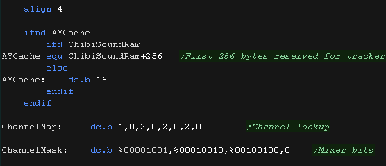
| We need some parameters! We have some cache ram to keep track of the AY register settings We have a 'ChannelMap' which allows us to simulate 8 possible virtual channels We have a 'ChannelMask' to get the bit pattern for the channels Mixer settings |
 |
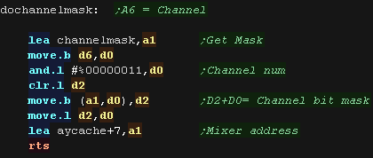
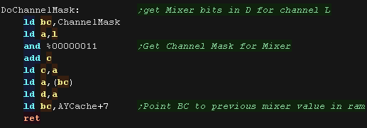
| DoChannelMask Will get the settings to set the current channels
mixers bits. it also points Point BC to previous mixer value in ram, in case we need it! |
 |
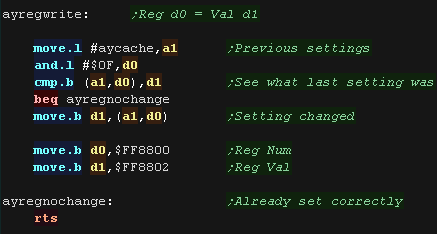
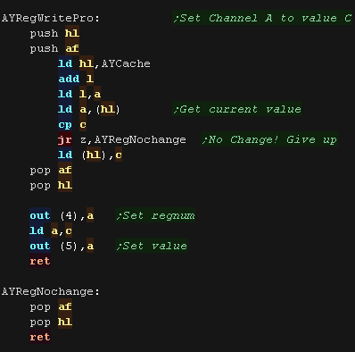
| AYRegWritePro will set an AY register if it's changed We will set reg A to value C. |
 |
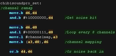
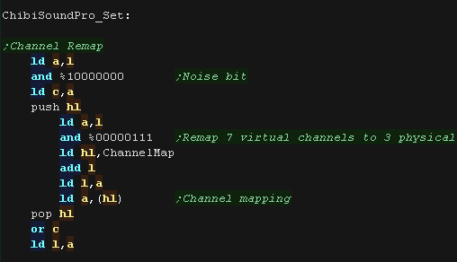
| ChibiSoundPro_Set will configure our sound channel H=Volume (0-255) L=Channel Num (0-127 unused channels will wrap around) / Top Bit=Noise DE=Pitch (0-65535) The channel number can be up to 128, so we remap it to channels 0-2 with the ChannelMap table |
 |
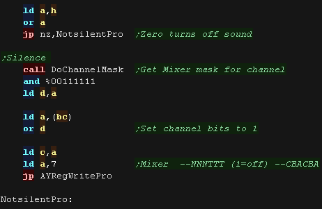
| Now we check the volume - if it's zero we want to silence the
channel. We do this by setting the channels Noise and Tone bits to 1 in the mixer (reg 7) |
 |
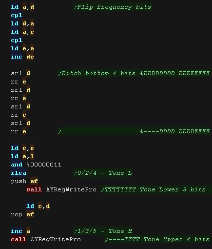
| We need to send the 12 bit frequency to the two registers for the
channel Channel 0 uses 0/1 Channel 1 uses 2/3 Channel 2 uses 4/5 We also need to flip the bits, as chibiSoundPro uses the value &FFFF as the highest frequency, but the AY uses &-000 |
 |
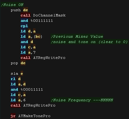
| If we need to make a noise, we need to clear the channel tone bit
in the mixer, and clear the noise bit to turn noise on We also set the 5 bit noise frequency in reg 6 |
 |
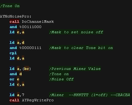
| If we want to make a tone... we need to set the noise bit (turning noise off) we need to clear the tone bit (turning tone on) |
 |
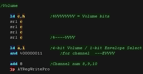
| Finally we set the volume. The AY uses a 4 bit volume, and this is set for the 3 channels with Reg 8/9/10 |
 |
 |
Lesson
P46 - Multiplatform Software tilemap on the X68000 (Mintile) We've written a minimal multiplatform Tile/Sprite routine in the Mintile series, Now, lets take a look at the platform specific code to quickly draw tiles to the screen on the X68000 |
 |
 X68_MinTile.asm
|
 |
| MinTile is a
multiplatform 'engine' which allows us to define our game code in
a common way, and let the platform specific code handle the
platform specific work!... it was used to write 'ChibiFighter' on
the Z80. For more details on Mintile, see the Mintile series here... |
|
Tile Drawing Routines
| Our example shows an onscreen tilemap and two software 'sprites'. Mintile supports scrolling and X-Flip (but not Y-flip) The 'sprites' are actually miniature tile maps, this is to reduce the amount of platform specific code. these are all created via the DoStrip platform specific routine, which we'll look at here. |
 |
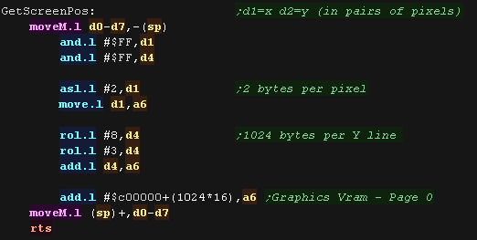
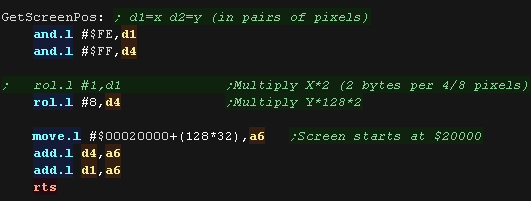
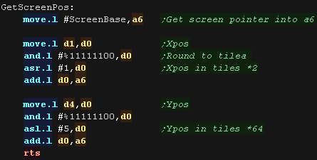
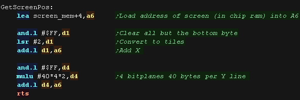
| We have a 'GetScreenPos' function , which calculates the VRAM
destination for the sprite objects. It calculates a VRAM destination in A6, from an X,Y position in D1,D4 Co-ordinates are in 'Logical Units' (Pairs of pixels) - this is to allow for single byte co-ordinates and maintain compatibility with the 8 bit systems |
 |
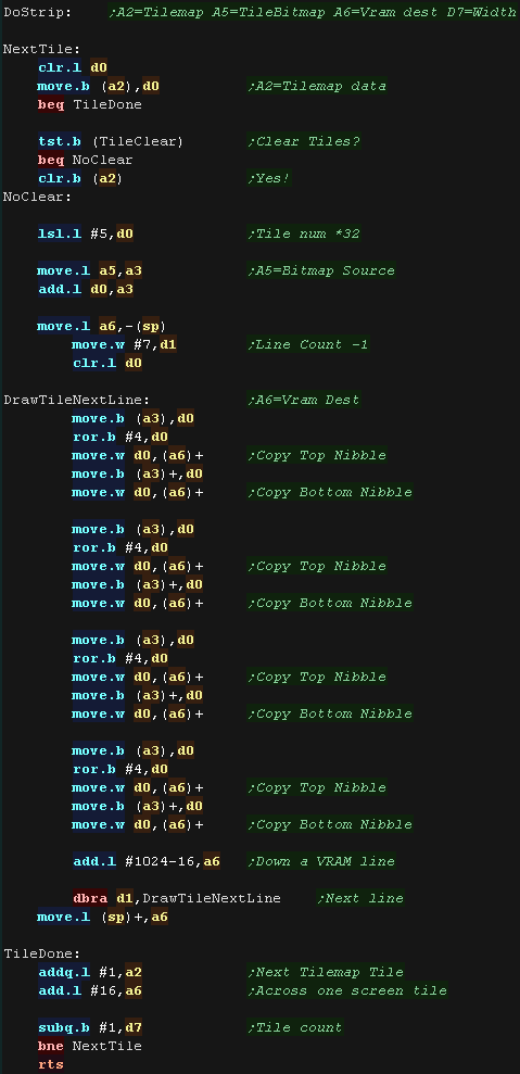
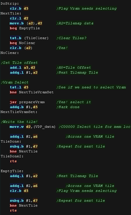
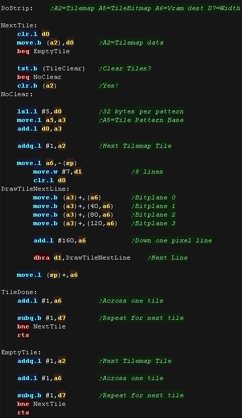
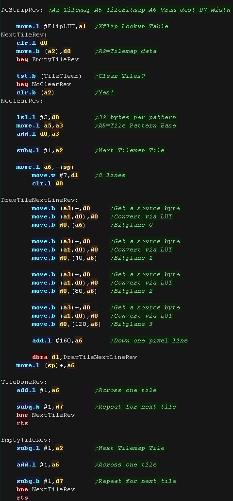
| DoStrip will draw one horizontal strip of tiles. The job is defined by the following registers: A2=Source Tilemap A5=Tile Bitmap Patterns A6=Vram destination D7=Width of strip The tilemap will either be the TileCache (for the background) or a mini tilemap (for sprites) If using the tile cache we zero the tiles after they are drawn. We calculate the address of the source pattern data by multiplying the tile number by 32 Each byte of the source pattern contains 2 pixels - one in each nibble. Irrespective of color depth, The VRAM on the X6800 has one pixel in each word. After each line we add 1024 to move down a line (minus the 16 bytes we wrote in the current tile) |
 |
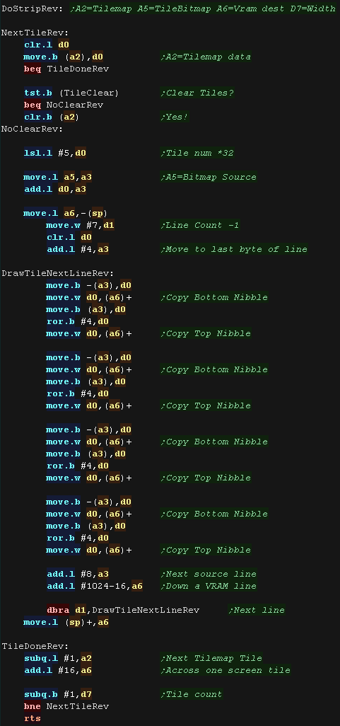
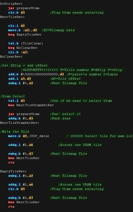
| DoStripRev has essentially the same function, however
we write the pixels in reverse order, and move through the source
tilemap in reverse. |
 |
 |
Lesson
P47 - Multiplatform Software tilemap on the Sinclair QL (Mintile) We've written a minimal multiplatform Tile/Sprite routine in the Mintile series, Now, lets take a look at the platform specific code to quickly draw tiles to the screen on the QL |
|
SQL_MinTile.asm
|
|
| MinTile is a
multiplatform 'engine' which allows us to define our game code in
a common way, and let the platform specific code handle the
platform specific work!... it was used to write 'ChibiFighter' on
the Z80. For more details on Mintile, see the Mintile series here... |
|
Tile Drawing Routines
| Our example shows an onscreen tilemap and two software 'sprites'. Mintile supports scrolling and X-Flip (but not Y-flip) The 'sprites' are actually miniature tile maps, this is to reduce the amount of platform specific code. these are all created via the DoStrip platform specific routine, which we'll look at here. |
 |
| We have a 'GetScreenPos' function , which calculates the VRAM
destination for the sprite objects. It calculates a VRAM destination in A6, from an X,Y position in D1,D4 Co-ordinates are in 'Logical Units' (Pairs of pixels) - this is to allow for single byte co-ordinates and maintain compatibility with the 8 bit systems Each line of the Sinclair QL is 128 bytes, and we skip 32 lines to center the virtual screen. |
 |
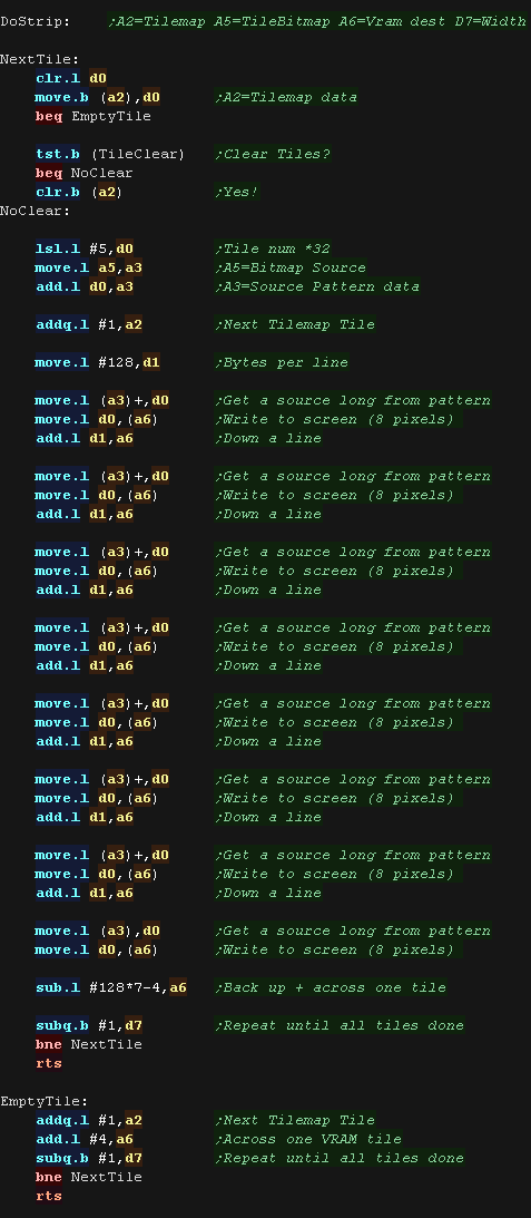
| DoStrip will draw one horizontal strip of tiles. The job is defined by the following registers: A2=Source Tilemap A5=Tile Bitmap Patterns A6=Vram destination D7=Width of strip The tilemap will either be the TileCache (for the background) or a mini tilemap (for sprites) If using the tile cache we zero the tiles after they are drawn. We calculate the address of the source pattern data by multiplying the tile number by 32 Each pair of bytes contain the data for 4 pixels, in the format %GFGFGFGF RBRBRBRB for the Red, Green, Blue and Flashing component. Moving a single Long moves 8 pixels - a whole line! After each line we add 128 to move down a line. we write all 8 lines with no loops for extra speed! After a tile we repeat for all the tiles on the line (the count is in D7) |
 |
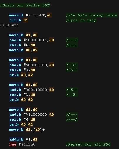
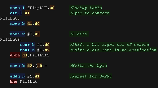
| We need to horizontally flip the bytes in the tiles,
and we'll do this via a 256 byte Lookup Table. For each of the 256 possible byte, We calculate the opposite position of the 4 pixels in the byte |
 |
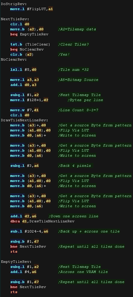
| DoStripRev has essentially the same function, however
we flip the pixels via the LUT We load A1 with the address of the lookup table, we then read in a byte into D0, and use the source byte as an offset in the lookup table. Reading from this resulting address gets the X-flipped equivalent byte, which we write to the screen. We write 4 times per line (4 pixels per word) and for all 8 lines |
 |
 |
Lesson
P48 - Multiplatform Software tilemap on the Genesis (Mintile) We've written a minimal multiplatform Tile/Sprite routine in the Mintile series, Now, lets take a look at the platform specific code to quickly draw tiles to the screen on the Megadrive / Genesis |
|
GEN_MinTile.asm
|
|
| MinTile is a
multiplatform 'engine' which allows us to define our game code in
a common way, and let the platform specific code handle the
platform specific work!... it was used to write 'ChibiFighter' on
the Z80. For more details on Mintile, see the Mintile series here... |
|
Tile Drawing Routines
| Our example shows an onscreen tilemap and two
software 'sprites' (they are actually tiles in this example). Mintile supports scrolling and X-Flip (but not Y-flip) The 'sprites' are actually miniature tile maps, this is to reduce the amount of platform specific code. these are all created via the DoStrip platform specific routine, which we'll look at here. |
 |
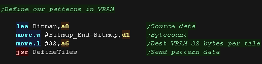
| On the Genesis we first want to load our pattern data
into Vram. Xflip is performed by the hardware, so we don't need to flip the patterns here. We select the VRAM destination for the tiles (Address 32 -skipping tile 0), and transfer the pattern bitmaps to VRAM |
 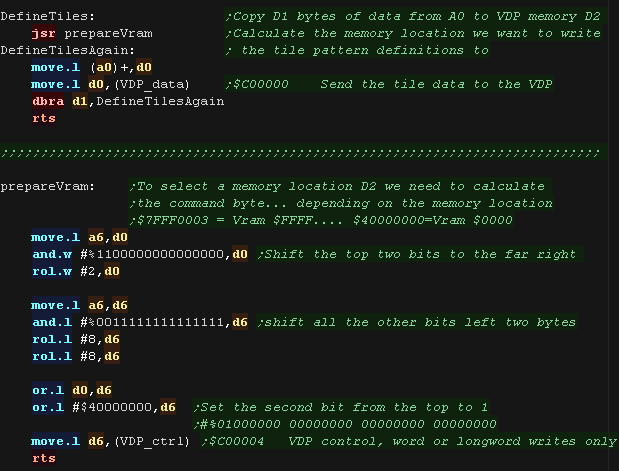 |
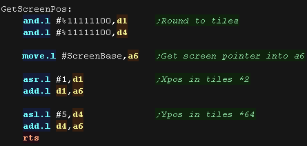
| We have a 'GetScreenPos' function , which calculates the VRAM
destination for the sprite objects. It calculates a VRAM destination in A6, from an X,Y position in D1,D4 Co-ordinates are in 'Logical Units' (Pairs of pixels) - this is to allow for single byte co-ordinates and maintain compatibility with the 8 bit systems Our formula for the VRAM of a tile is VRAM Addr = $C000 + (Ypos * 64* 2) + (Xpos *2) |
 |
| DoStrip will draw one horizontal strip of tiles. The job is defined by the following registers: A2=Source Tilemap A5=Tile Pattern offset A6=Vram destination D7=Width of strip The tilemap will either be the TileCache (for the background) or a mini tilemap (for sprites) If using the tile cache we zero the tiles after they are drawn. We set the tile number - it's defined by 2 bytes in the format: %LPPVHTTTtttttttt Where: T=Tile number H=Hflip V=vflip P=palette number L=Layer The VRAM destination is tracked in A6... if we have to skip tiles, we set a flag in D5 to ensure next time a tile is drawn we update the VRAM destination |
 |
| DoStripRev has essentially the same function, we just
set bit 11 of the tile parameters to X-flip the tile. |
 |
|
Lesson
P49 - Multiplatform tilemap on the Genesis (Mintile) with Hardware
sprites Lets add Hardware sprites to our previous tilemap example |
|
GEN_MinTile_Sprite.asm
|
|
| MinTile is a
multiplatform 'engine' which allows us to define our game code in
a common way, and let the platform specific code handle the
platform specific work!... it was used to write 'ChibiFighter' on
the Z80. For more details on Mintile, see the Mintile series here... |
|
Tile Drawing Routines
| Lets add some extra code to our previous example, we'll add two new strip drawing routines which use hardware sprites to draw our moving characters. |  |
| As before we first want to load our pattern data into
Vram. Xflip is performed by the hardware, so we don't need to flip the patterns here. We select the VRAM destination for the tiles (Address 32 -skipping tile 0), and transfer the pattern bitmaps to VRAM |
|
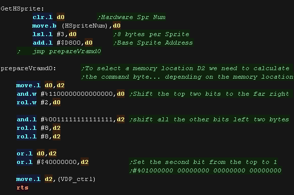
| We have a 'GetScreenPos' function , which calculates the VRAM
destination for the sprite objects. It calculates a VRAM destination in A6, from an X,Y position in D1,D4 Co-ordinates are in 'Logical Units' (Pairs of pixels) - this is to allow for single byte co-ordinates and maintain compatibility with the 8 bit systems Our formula for the VRAM of a tile is VRAM Addr = $C000 + (Ypos * 64* 2) + (Xpos *2) This version is modified, it preserves D1,D4 for the sprite co-rdinates |
 |
| We use 'HSpriteNum' to track the next free hardware sprite. Hardware sprites are defined in VRAM, each sprite takes 8 bytes, and these start from VRAM address $D800 There are 80 sprites in total |
 |
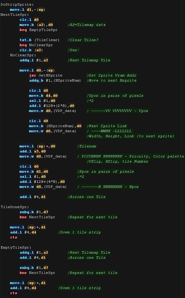
| DoStripSprite will draw one horizontal strip
of sprites from the tilemap. The job is defined by the following registers: A2=Source Tilemap A5=Tile Pattern offset A6=Vram destination D7=Width of strip The tilemap will either be the TileCache (for the background) or a mini tilemap (for sprites) If using the tile cache we zero the tiles after they are drawn. We use D1,D4 as the X,Y pos (in pairs of pixels) We write 8 bytes to VRAM in the following order: %------VV VVVVVVVV - Vpos %----WWHH -LLLLLLL - Width, Height, Link (to next sprite) %PCCVHNNN NNNNNNNN - Priority, Color palette Vflip, Hflip, tile Number %-------H HHHHHHHH - Hpos Each sprite needs to 'link' to the next in order for the sprites to draw correctly. |
 |
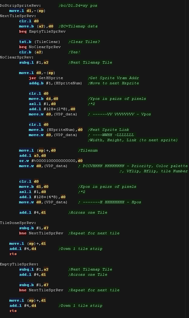
| DoStripSpriteRevhas essentially the same function, we
just set the Hflip bit |
 |
| As each sprite 'Links' to the last, After we've drawn everything onscreen, we set the final sprite with a position of 0, and linking back to sprite 0 | 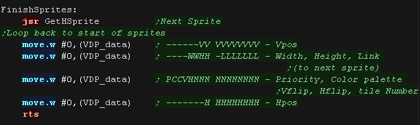 |
 |
Lesson
P50 - Multiplatform Software tilemap on the Amiga (Mintile) We've written a minimal multiplatform Tile/Sprite routine in the Mintile series, Now, lets take a look at the platform specific code to quickly draw tiles to the screen on the Amiga |
|
AMI_MinTile.asm
|
|
| MinTile is a
multiplatform 'engine' which allows us to define our game code in
a common way, and let the platform specific code handle the
platform specific work!... it was used to write 'ChibiFighter' on
the Z80. For more details on Mintile, see the Mintile series here... |
|
Tile Drawing Routines
| Our example shows an onscreen tilemap and two software 'sprites'. Mintile supports scrolling and X-Flip (but not Y-flip) The 'sprites' are actually miniature tile maps, this is to reduce the amount of platform specific code. These are all created via the DoStrip platform specific routine, which we'll look at here. This example writes to the screen in software. |
 |
| We have a 'GetScreenPos' function , which calculates the VRAM
destination for the sprite objects. It calculates a VRAM destination in A6, from an X,Y position in D1,D4 Co-ordinates are in 'Logical Units' (Pairs of pixels) - this is to allow for single byte co-ordinates and maintain compatibility with the 8 bit systems Each line of the screen is 40 bytes, but there are 4 bitplanes. |
 |
| DoStrip will draw one horizontal strip of tiles. The job is defined by the following registers: A2=Source Tilemap A5=Tile Bitmap Patterns A6=Vram destination D7=Width of strip The tilemap will either be the TileCache (for the background) or a mini tilemap (for sprites) If using the tile cache we zero the tiles after they are drawn. We calculate the address of the source pattern data by multiplying the tile number by 32 There are 4 bitplanes for each tile, spaced 40 bytes apart. After each line we add 160 to move down a line. we repeat 8 times After a tile we repeat for all the tiles on the line (the count is in D7) |
 |
| We need to horizontally flip the bytes in the tiles,
and we'll do this via a 256 byte Lookup Table. For each of the 256 possible bytes, We calculate the opposite position of the 8 pixels of a bitplane |
 |
| DoStripRev has essentially the same function, however
we flip the pixels via the LUT We load A1 with the address of the lookup table, we then read in a byte into D0, and use the source byte as an offset in the lookup table. Reading from this resulting address gets the X-flipped equivalent byte, which we write to the screen. We write 4 times per line and for all 8 lines |
 |
| View Options |
| Default Dark |
| Simple (Hide this menu) |
| Print Mode (white background) |
| Top Menu |
| ***Main Menu*** |
| Youtube channel |
| Patreon |
| Introduction to Assembly (Basics for absolute beginners) |
| Amazon Affiliate Link |
| AkuSprite Editor |
| ChibiTracker |
| Dec/Bin/Hex/Oct/Ascii Table |
| Alt Tech |
| Archive.org |
| Bitchute |
| Odysee |
| Rumble |
| DailyMotion |
| Please note: I wlll upload more content to these alt platforms based on the views they bring in |
| 68000 Content |
| ***68000 Tutorial List*** |
Learn 68000 Assembly  |
| Hello World Series |
| Platform Specific Series |
| Simple Samples |
| Grime 68000 |
| 68000 Downloads |
| 68000 Cheatsheet |
| Sources.7z |
| DevTools kit |
| 68000 Platforms |
| Amiga 500 |
| Atari ST |
| Neo Geo |
| Sega Genesis / Mega Drive |
| Sinclair QL |
| X68000 (Sharp x68k) |
| 8086 Content |
| Learn 8086 Assembly |
| Platform Specific Series |
| Hello World Series |
| Simple Samples |
| 8086 Downloads |
| 8086 Cheatsheet |
| Sources.7z |
| DevTools kit |
| 8086 Platforms |
| Wonderswan |
| MsDos |
| ARM Content |
| Learn ARM Assembly |
| Learn ARM Thumb Assembly |
| Platform Specific Series |
| Hello World |
| Simple Samples |
| ARM Downloads |
| ARM Cheatsheet |
| Sources.7z |
| DevTools kit |
| ARM Platforms |
| Gameboy Advance |
| Nintendo DS |
| Risc Os |
| Risc-V Content |
| Learn Risc-V Assembly |
| Risc-V Downloads |
| Risc-V Cheatsheet |
| Sources.7z |
| DevTools kit |
| MIPS Content |
| Learn Risc-V Assembly |
| Platform Specific Series |
| Hello World |
| Simple Samples |
| MIPS Downloads |
| MIPS Cheatsheet |
| Sources.7z |
| DevTools kit |
| MIPS Platforms |
| Playstation |
| N64 |
| PDP-11 Content |
| Learn PDP-11 Assembly |
| Platform Specific Series |
| Simple Samples |
| PDP-11 Downloads |
| PDP-11 Cheatsheet |
| Sources.7z |
| DevTools kit |
| PDP-11 Platforms |
| PDP-11 |
| UKNC |
| TMS9900 Content |
| Learn TMS9900 Assembly |
| Platform Specific Series |
| Hello World |
| TMS9900 Downloads |
| TMS9900 Cheatsheet |
| Sources.7z |
| DevTools kit |
| TMS9900 Platforms |
| Ti 99 |
| 6809 Content |
| Learn 6809 Assembly |
| Learn 6309 Assembly |
| Platform Specific Series |
| Hello World Series |
| Simple Samples |
| 6809 Downloads |
| 6809/6309 Cheatsheet |
| Sources.7z |
| DevTools kit |
| 6809 Platforms |
| Dragon 32/Tandy Coco |
| Fujitsu FM7 |
| TRS-80 Coco 3 |
| Vectrex |
| 65816 Content |
| Learn 65816 Assembly |
| Hello World |
| Simple Samples |
| 65816 Downloads |
| 65816 Cheatsheet |
| Sources.7z |
| DevTools kit |
| 65816 Platforms |
| SNES |
| eZ80 Content |
| Learn eZ80 Assembly |
| Platform Specific Series |
| eZ80 Downloads |
| eZ80 Cheatsheet |
| Sources.7z |
| DevTools kit |
| eZ80 Platforms |
| Ti84 PCE |
| IBM370 Content |
| Learn IBM370 Assembly |
| Simple Samples |
| IBM370 Downloads |
| IBM370 Cheatsheet |
| Sources.7z |
| DevTools kit |
| Super-H Content |
| Learn SH2 Assembly |
| Hello World Series |
| Simple Samples |
| SH2 Downloads |
| SH2 Cheatsheet |
| Sources.7z |
| DevTools kit |
| SH2 Platforms |
| 32x |
| Saturn |
| PowerPC Content |
| Learn PowerPC Assembly |
| Hello World Series |
| Simple Samples |
| PowerPC Downloads |
| PowerPC Cheatsheet |
| Sources.7z |
| DevTools kit |
| PowerPC Platforms |
| Gamecube |
| Work in Progress |
| ChibiAndroids |
| Misc bits |
| Ruby programming |
Buy my Assembly programming book
on Amazon in Print or Kindle!


Available worldwide!
Search 'ChibiAkumas' on
your local Amazon website!
Click here for more info!


Buy my Assembly programming book
on Amazon in Print or Kindle!
Available worldwide!
Search 'ChibiAkumas' on
your local Amazon website!
Click here for more info!
Buy my Assembly programming book
on Amazon in Print or Kindle!
Available worldwide!
Search 'ChibiAkumas' on
your local Amazon website!
Click here for more info!