

Platform Specific Lessons
Platform Specific Series - Lets learn how the hardware of the systems work, so we can get it to do what we want... Covers Amsrad CPC,MSX,ZX Spectrum, TI-83,Enterprise 128/64 and Sam Coupe!
Making a tape with 2CDT
| We're using 2CDT to build a tape file... Our test program has
two types: 2 files are saved normally with blocks (The RLE compressed Cinema) 1 file is saved headerless (The final thanks message) 2CDT takes a variety of switches we'll need: ;-n = start New tape ;-s 1 = Speed 2000 Baud (fast) ;-m 0 = Add Block data (use with &BC77) ;-t 1 = Turbo Loading blocks (default) ;-m 1 = Add Headerless (use with &BCA1) |
 |
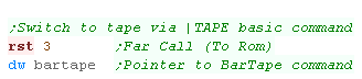
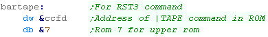
| Our demo is started with CALL &4000 ... We're running on an AMSTRAD 6128 - this system starts with reading from disk - we need to use the basic command "|TAPE" There's no defined firmware command to do this, but we can do a 'FAR CALL' (Call to ROM) with RST3 This command takes a pointer to 3 bytes... the first two are a destination address (&CCFD for |TAPE) and the third is a ROM NUMBER (7 for the DISK ROM which contains the command) |
  |
By default the CPC will show tape messages - we'll want to turn this off. |
 |
| We do this with &BC6B (CAS NOISY)... passing this a 0 in A will enable messages (Default)... we want to turn them off so we set A=1 | 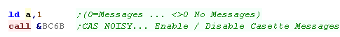 |
Tape loading... Reading Bytes (With Blocks)
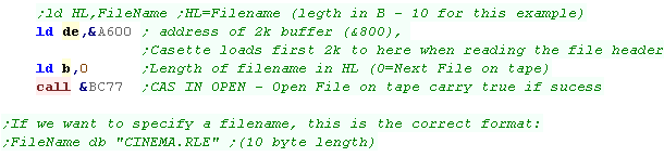
| We're going to open a file on the tape... it's RLE data, and we'll
process it a byte at a time. We need to specify a memory address of a 2k buffer - we do this with DE If we want to specify the filename to load, we specify a pointer to the name in HL - and the filename length in B... alternatively we can specify B=0 to just load the next file on the tape. We then use function &BC77 (CAS IN OPEN) to open the cassette file |
 |
||||||
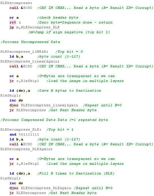
| we use &BC80 (CAS IN CHAR) to read in a single byte from the
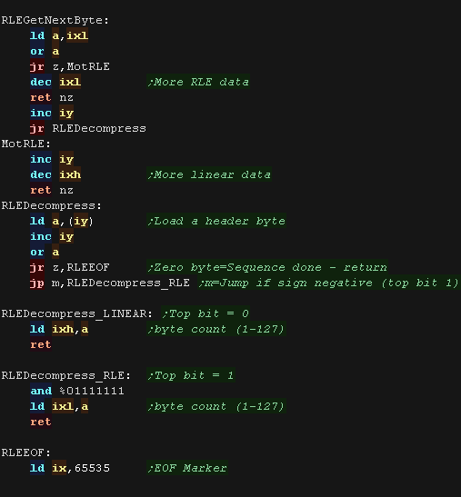
file... We're using the RLE decoder we looked at previously to show the cinema graphic Each section has a 'header byte' If the whole byte is zero - then we're reached the end of the compressed sequence If the top bit is 1, the next sequence is RLE compressed... the remaining bits are a bytecount (1-127) If the top bit is 0, the next sequence is LINEAR uncompressed data... the remaining bits are a bytecount (1-127) |
 |
||||||
The RLE decompressor has been modified to skip zero bytes, allowing multiple layers to be overlaid to build up an image.
|
|||||||
| Once we've loaded in the file we use &BC7A (CAS IN CLOSE) to close the file. | 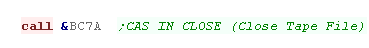 |
||||||


| If you don't
want to do anything clever with the file byte by byte, and want to
read in blocks, use &BC83
- CAS IN DIRECT Specify a destination address with HL,and the file will be loaded into ram. |
 |
Tape loading... Reading to ram (Headerless)
| If we want to quickly load a large block of data, Headerless data
is fastest... we load headerless data with &BCA1 (CAS READ) As there's no header, we don't specify a filename... there's no blocks, so the data is quicker. We need to specify a destination in HL, a size in DE... and a Header sync byte in A (this needs to match the one used to build the file - 2CDT and the amstrad BIOS default to &16 for data) |
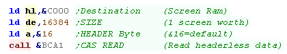 |
| This can be used for reading in a loading screen in one go. |  |
| This
example scales images on the CPC... but the principal will work on
any system which uses a bitmap screen (Like the SAM or Speccy) Scaling sprites can be used for a neat effect - it could also be used to save memory if you want huge graphics - of course a sprite scaled 2x in both directions uses 1/4 of the size of an unscaled sprite. |
 |
Sprite scaling and the Lookup tables
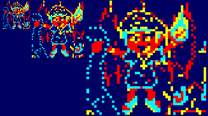
| We're going to scale our Chibiko sprite - here it's shown at 1x ,
2x and 4x size. The sprite file is the same as the one used in the simple series. and the code used to display the 1x version is almost the same (It uses different registers for convenience to match the 2x and 4x versions) |
 |
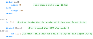
| We need some lookup tables to convert the bytes to 2x and 4x...
these contain the new scaled 'screen bytes' There are 256 possible screen bytes at 1x 2x needs a 512 byte Lookup Table 4x needs a 1024 byte Lookup Table As MODE 0 only has 2 pixels per byte, we don't actually need the 4x lookup table in Mode 0 |
 |
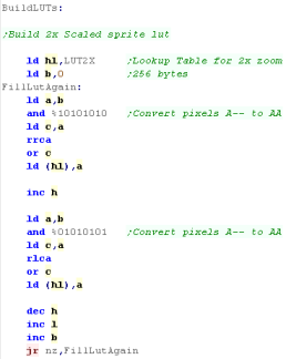
Building the Lookup Tables
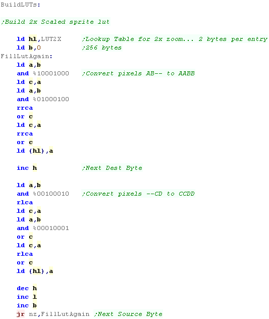
| Before we use the draw routines, we need to fill the LUT's... The lookup tables are byte aligned If the 2x LUT is at &16xx... &16xx will be the First byte of the conversion for screen byte xx &17xx will be the Second byte of the conversion for screen byte xx The same is true for the 4x LUT... but it will use addresses &18xx &19xx &20xx and &21xx for the 4 output bytes We need to mask each pixel of the source byte, and fill the destination byte with OR commands We need to understand how the screen pixels work to do this... here we're building the 2x scale for Mode 1 |
 |
| It's pretty much the same for the MODE 1 4x scale routine. | 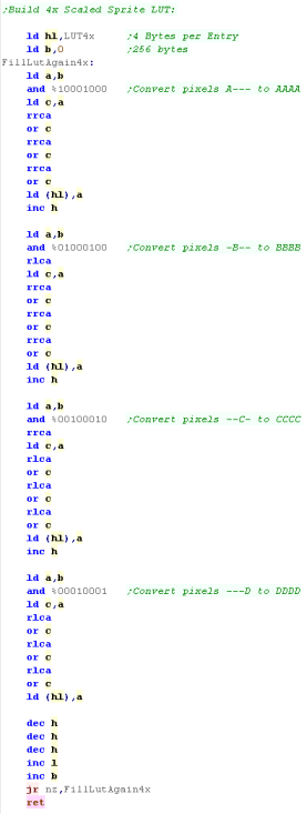 |
| The MODE 0 2x scaling routine is almost the same, just the mask
and shifts are different. There is no 4x LUT for Mode 0 - because there are only two pixels per byte, we can use the 2x LUT for the 4x version (we just use each entry twice) |
 |
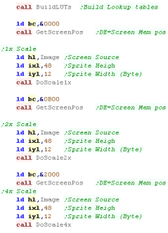
Drawing the sprites!
| We're going to draw our sprite!... We have 3 different routines for each of the scales. We use 'GetScreenPos' to calculate the screen ram location... this is the same as in the Simple Series. |
 |
| Here's the 1x routine, we read each pixel from the source bitmap in HL... and transfer them to the screen at DE | 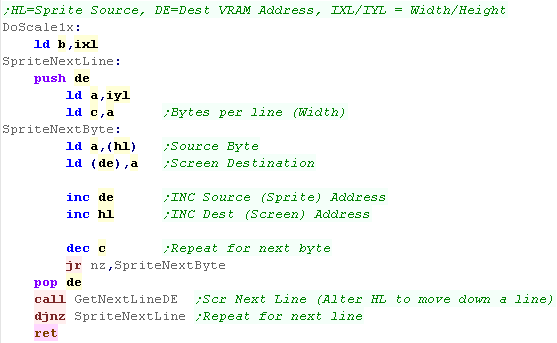 |
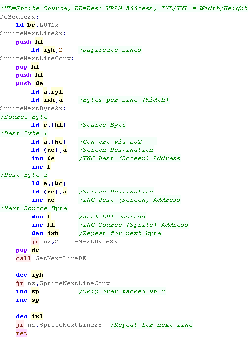
| When we want to scale the source sprite 2x we use the lookup
table. We read a byte as before from HL... but this time we load the lookup table into BC. We swap C for the byte from HL - BC now points to the first conversion for that byte We transfer the first byte from BC to the screen (This is the first of the 2x scaled equivalents of the byte from HL) We increment B - BC now points to the second conversion for that byte We transfer the first byte from BC to the screen (This is the first of the 2x scaled equivalents of the byte from HL) We repeat the procedure for the next source byte. |
 |
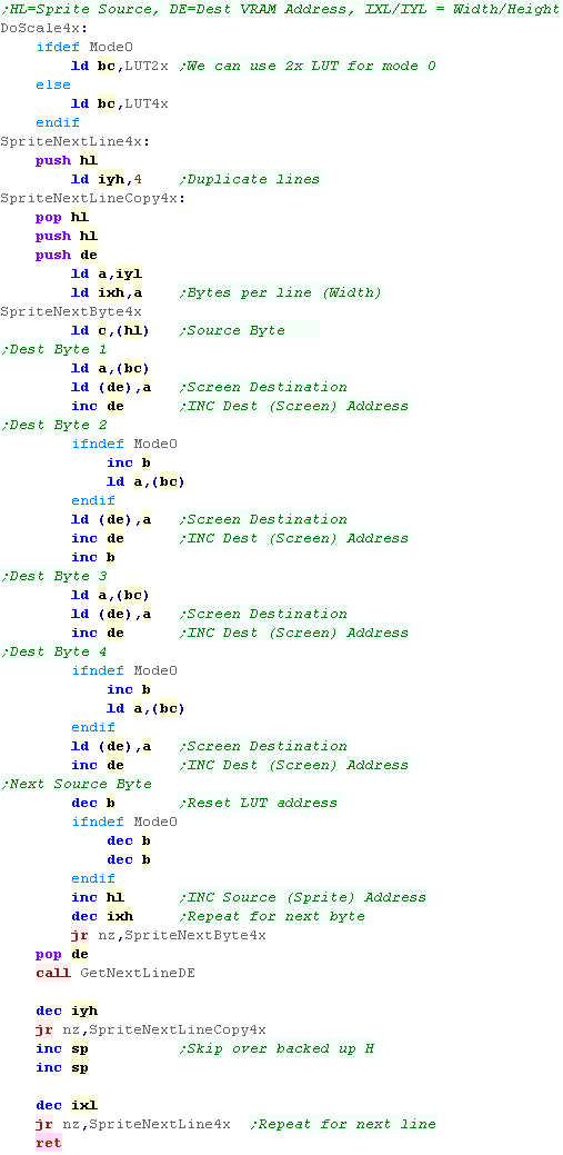
The 4x procedure is the same... of course we use the 4x scaling LUT form Mode 1this time. This time We transfer 4 bytes from the LUT to the screen We INC B four times in MODE 2 for the 4 destination byte. In Mode 0 we use the 2x LUT - and we write each byte from the LUT twice... INCing B twice - this is because there's only 2 pixels per byte, so there's no need for another LUT We can also use the 4x LUT for 8X if we want super blocky sprites for some reason! |
 |
Our Test program.
| We're going to create a test program. It will read the mouse via the joystick port and move a cursor around the screen. When you click the left mouse button, it will draw a 'Chibiko' (our vampire mascot) When you drag the left mouse button it will draw a blob trail. For speed and simplicity, All sprites will be drawn with 'XOR' meaning a sprite will be removed if it's drawn in the same position twice. |
 |
Reading the Mouse (Joystick)
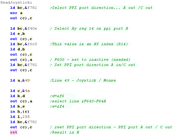
| We read the joystick in the same way as the keyboard - we need to
select the row of the keyboard we want to read, and read that line
in via the AY We read in line &49 - the line for Joystick 1 - this contains all the joystick buttons the mouse use. |
 |
Keyboard Matrix
The Keyboard matrix uses 7 bits of line &49 for the Joystick - 4 directions and up to 3 firebuttons.
Fire 3 is undocumented, but is supported on the classic CPC as middle mouse - however it is NOT supported on the CPC+
| 0 | 1 | 2 | 3 | 4 | 5 | 6 | 7 | |
| &40 | C-U | C-R | C-D | F9 | F6 | F3 | F-ENT | F. |
| &41 | C-L | CPY | F7 | F8 | F5 | F1 | F2 | F0 |
| &42 | c | [ | RET | ] | 4 | SHIFT | \ | c |
| &43 | ^ | - | @ | P | ; | : | / | . |
| &44 | 0 | 9 | O | I | L | K | M | , |
| &45 | 8 | 7 | U | Y | H | J | N | |
| &46 | 6 J2-U | 5 J2-D | R J2-L | T J2-R | G J2-F1 | F J2-F2 | B J2-F3 | V |
| &47 | 4 | 3 | E | W | S | D | C | X |
| &48 | 1 | 2 | ESC | Q | TAB | A | CAPS | Z |
| &49 | J1-U | J1-D | J1-L | J1-R | J1-F1 | J1-F2 | J1-F3 | DEL |
Our Mouse Routine
| We're going to use a custom interrupt handler, this ensures mouse movements wont be missed if our program gets slow. | 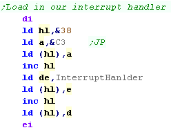 |
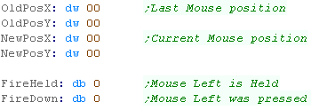
| We're going to need some variables We'll store the mouse position - we keep the last position so we know where the mouse was last time we drew it (so we can remove the old sprite) We use 16 bit X,Y co-ordinates so we can have 'half movements' - we use the top byte of the X,Y pos for drawing... Our drawing routine works in screen bytes - so the Mode 1 screen is 80x200 - meaning we need to move 1 unit in the X axis for every 4 or so in the Y axis. |
 |
| We need to process each of the 4 directions... Up, Down, Left
and Right We check for each direction, and if it's pressed - we check the current location If we're already at the edge of the screen, we don't want to move again, but if our current position is OK, we add or subtract the move as required and update the cursor position. |
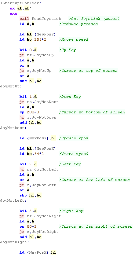 |
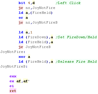
| We also test the fire button, and if it's down we set our fire
markers... if it's released we clear the held marker. (The fire down marker should be cleared by the routine that uses the mouse) |
 |
 |
This example
just processes the left mouse button - we could mimic this for
the right and even center buttons. Just remember - Fire 3 (Center) will not work on the CPC+! |
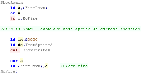
| We're going to use our mouse... First we test if fire was just
pressed... if it was we'll show 'TestSprite2' (Chibiko) at our
current location We need to clear the Fire down event to mark it processed |
 |
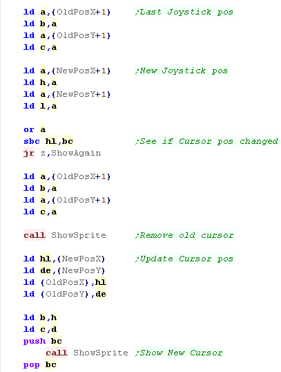
| We're going to update the cursor - first we check if the old
position and new position are the same - if so we have nothing to
do. If the cursor has moved, first we redraw the cursor in the old position - as we're using XOR sprites this removes the old cursor, Next we draw the cursor in the new position Finally we copy the new cursor position into the old cursor position - for the next run of the main loop |
 |
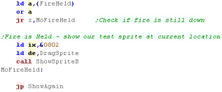
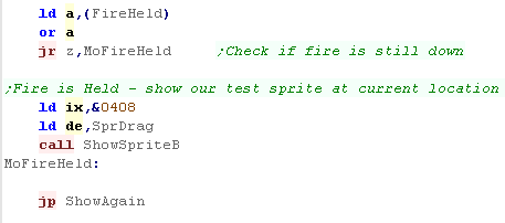
| Finally we'll process Fire held... this routine only runs if the
cursor has moved. If fire is held, we show a blob at the current position We do NOT clear the fire held flag - it's cleared by the interrupt handler. |
 |


Mouse Routine
| Reading the Kempston mouse is super easy! Ww just read 3 ports Reading &FBDF We can get an 'X position' Reading &FFDF We can get an 'Y position' Reading &FADF gets the Left and right mouse buttons in the format %000000LR |
 |
| Here is some sample code to read the XY pos of the mouse in HL - and the Buttons in A | 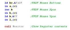 |
 |
Note X and Y position read from &FBDF
and &FFDF do not give positions on the screen - they are
relative movements positions. X=0 does not mean far left, nor does 255 mean far right... all we know is if the X pos goes down the mouse moved left... and if the Y pos goes down the mouse moved down. |
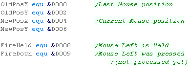
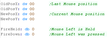
| We're going to need some variables We'll store the mouse position - we keep the last position so we know where the mouse was last time we drew it (so we can remove the old sprite) We use 16 bit X,Y co-ordinates so we can have 'half movements' - we use the top byte of the X,Y pos for drawing... We also need two bytes to compare the last XY position to the current one (Xmove and Ymove) |
|
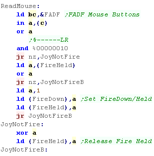
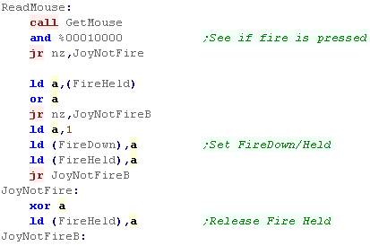
| First we test the fire button with port &FADF, and
if it's down we set our fire markers... if it's released we clear the held marker. (The fire down marker should be cleared by the routine that uses the mouse) |
 |
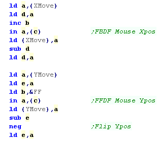
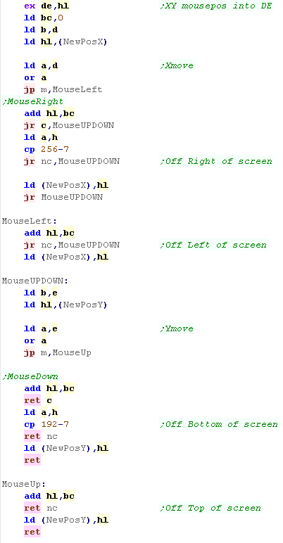
| We read in the current X and Y position from &FBDF
and &FFDF We subtract these from the last read in value to get a movement distance - we flip the Y axis to match our screen co-ordinates. |
 |
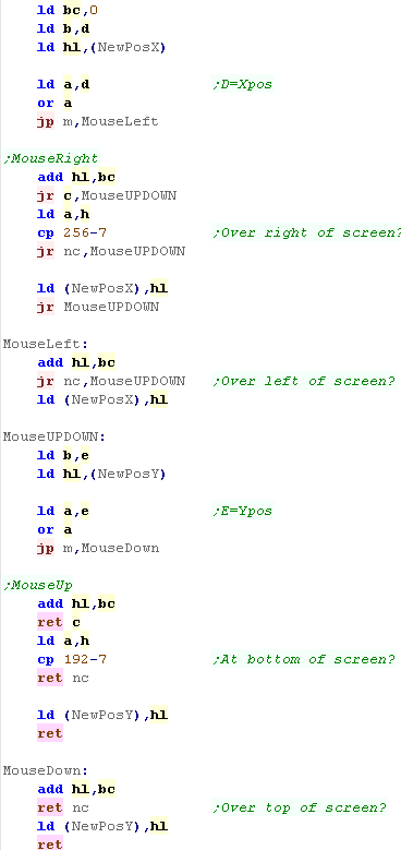
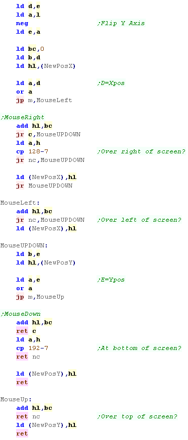
| We use these Xmove and Ymove values (now in Reg D and E) to
alter the mouse position. When we add or subtract the movement from each axis, we need to check if this causes an overflow, If we go below zero, then we've gone over the top or left edge of the screen... If we go over X>256-7 or Y>192-7 then we've hit the right or bottom of the screen. We've now converted the movement to a valid onscreen mouse position |
 |
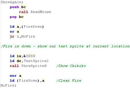
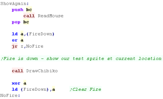
| We're going to use our mouse... First we test if fire was just
pressed... if it was we'll show 'TestSprite2' (Chibiko) at our
current location We need to clear the Fire down event to mark it processed. |
 |
| We're going to update the cursor - first we check if the old
position and new position are the same - if so we have nothing
to do. If the cursor has moved, first we redraw the cursor in the old position - as we're using XOR sprites this removes the old cursor, Next we draw the cursor in the new position Finally we copy the new cursor position into the old cursor position - for the next run of the main loop |
|
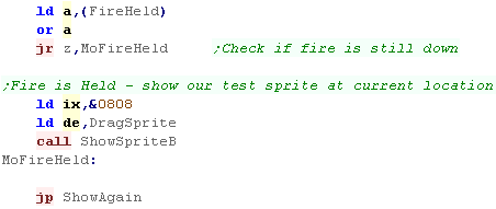
| Finally we'll process Fire held... this routine only runs if
the cursor has moved. If fire is held, we show a blob at the current position We do NOT clear the fire held flag - it's cleared by the mouse reading routine. |
 |

Mouse Routine
| Bit | Direction | Details | Joy Function | Mouse Function |
| 0 | IN | J1-Pin 1 / J2-Pin 1 | Up | Low/High Bit 0 |
| 1 | IN | J1-Pin 2 / J2-Pin 2 | Down | Low/High Bit 1 |
| 2 | IN | J1-Pin 3 / J2-Pin 3 | Left | Low/High Bit 2 |
| 3 | IN | J1-Pin 4 / J2-Pin 4 | Right | Low/High Bit 3 |
| 4 | IN | J1-Pin 6 / J2-Pin 6 | Fire 1 | Right Button |
| 5 | IN | J1-Pin 7 / J2-Pin 7 | Fire 2 | Left Button |
| 6 | IN | Key Layout Select (JP version only) | ||
| 7 | IN | Cassette Read |
| Bit | Direction | Details | Joy Function | Mouse Function |
| 0 | OUT | J1-Pin 6 | Set to 1 | Set to 1 |
| 1 | OUT | J1-Pin 7 | Set to 1 | Set to 1 |
| 2 | OUT | J2-Pin 6 | Set to 1 | Set to 1 |
| 3 | OUT | J2-Pin 7 | Set to 1 | Set to 1 |
| 4 | OUT | J1-Pin 8 | Get Low/High Nibble | |
| 5 | OUT | J2-Pin 8 | Get Low/High Nibble | |
| 6 | OUT | Port A Input Select | Joy 1/2 | Mouse 1/2 |
| 7 | OUT | Kana Lamp On/Off |
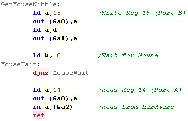
| When we want to read a nibble from an axis, we need to send the
configuration to port B to set up the mouse, We then read from port A to get the data from the mouse |
 |
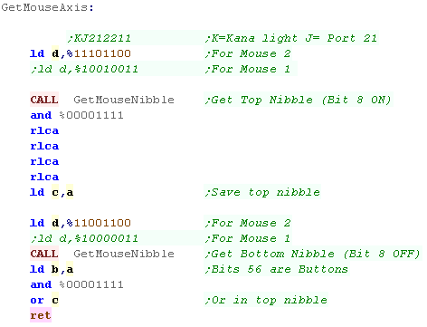
| We need to send the correct data to port B - the bits we need to
set are different depending if our mouse is in joystick port 1 or
2 The settings here are reading a mouse in joystick port 2 - use the REMmed out versions for joystick port 1 Here we're reading and combining the high and low nibbles - this gets one axis. |
 |
| We run the GetMouseAxis command twice - this reads both the X
and Y axis... A will also contain the Left/Right mouse buttons in bits 4,5 - we set all the other bits to 1 |
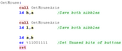 |
| Here's a simple routine to read in the mouse data, and convert it to an XY position in BC... A contains the LR Mouse buttons. | 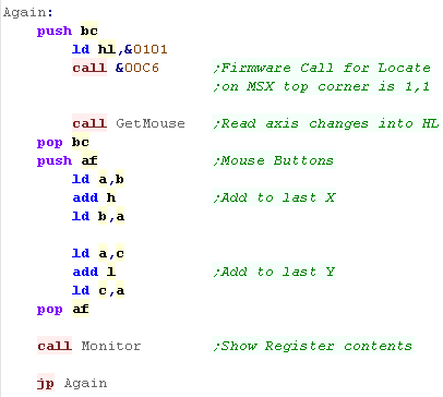 |
|
Note X and Y position read from here do
not give positions on the screen - they are relative movements
positions compared to the last read - even when we add them to
previous reads, they are still only a 'relative movement - we
need to covert this to a screen co-ordinate. |
| We're going to write a little mouse drawing routine, It will show a cursor that's limited to the screen area, we'll be able to click to draw a 'Chibiko', and click and drag to draw blobs. This is written on the MSX2 |
 |
| We're going to need some variables We'll store the mouse position - we keep the last position so we know where the mouse was last time we drew it (so we can remove the old sprite) We use 16 bit X,Y co-ordinates so we can have 'half movements' - we use the top byte of the X,Y pos for drawing... |
 |
| First we test the fire button - it's still in the
Accumulator, and if it's down we set our fire markers... if it's released we clear the held marker. (The fire down marker should be cleared by the routine that uses the mouse) |
 |
| We transfer the read in XY pos into DE NOTE: The mouse reading routine has been flipped... a NEG command has been added to GetMouseNibble When we add or subtract the movement from each axis, we need to check if this causes an overflow, If we go below zero, then we've gone over the top or left edge of the screen... If we go over X>256-7 or Y>192-7 then we've hit the right or bottom of the screen. We've now converted the movement to a valid onscreen mouse position |
 |
 |
This
code uses MSX2 VDP commands to do the graphics work... if
you don't know about them, you can learn more Here |
| We're going to use our mouse... First we test if fire was
just pressed... if it was we'll show 'TestSprite2' (Chibiko)
at our current location We need to clear the Fire down event to mark it processed. |
 |
| We're going to update the cursor - first we check if the old
position and new position are the same - if so we have nothing
to do. If the cursor has moved, first we redraw the cursor in the old position - as we're using XOR sprites this removes the old cursor, Next we draw the cursor in the new position Finally we copy the new cursor position into the old cursor position - for the next run of the main loop |
 |
| Finally we'll process Fire held... this routine only runs if
the cursor has moved. If fire is held, we show a blob at the current position We do NOT clear the fire held flag - it's cleared by the mouse reading routine. |
 |

|
Generally,
the tech manual"sam-coupe_tech-man_v3-0.pdf" is pretty awesome,
but the documentation on the mouse is a massive pile of suck!...
Either that or the author of these tutorials is too stupid to
understand them (Either is possible!) As the documentation was lacking, today's example was written by trial and error, it seems to work fine, but no promises can be made! |
Mouse Port on the SAM
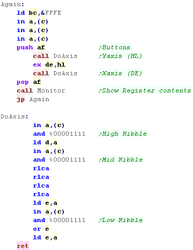
| The SAM Coupe mouse is read
from port &FFFE, We need to do sequential reads from that port, and look at the bottom 4 bits. We need to combine combine 3 nibbles to build the 12 bit X and Y movement. |
Successive reads from &FFFE will return the following data:
|
|||||||||||||||||||||||||||||||||||||||||||||||||||||||||||||||||||||||||||||||||||||||||||||||||||
| We need to read in 3 times from &FFFE to start, the last
gets us the mouse buttons, Now we do 3 reads, these will be the Y axis Then we do 3 more reads, these will be the X axis |
 |
|||||||||||||||||||||||||||||||||||||||||||||||||||||||||||||||||||||||||||||||||||||||||||||||||||
Our Mouse Routine
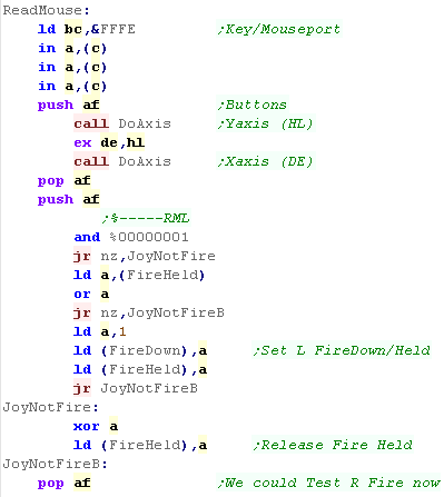
| We're going to write a mouse reader which will draw a cursor
onscreen. Clicking the left button will draw a 'Chibiko' mascot, dragging will draw a trail of blobs, The sprites are XOR, so drawing twice will remove a sprite. |
 |
| We're going to need some variables We'll store the mouse position - we keep the last position so we know where the mouse was last time we drew it (so we can remove the old sprite) We use 16 bit X,Y co-ordinates so we can have 'half movements' - we use the top byte of the X,Y pos for drawing... |
 |
| First read in 3 times and test the fire button with port &FFFE,
and if it's down we set our fire markers... if it's released we clear the held marker. (The fire down marker should be cleared by the routine that uses the mouse) We use the DoAxis function to read in the Y and X move |
 |
| We use these Xmove and Ymove values (now in Reg D and E) to
alter the mouse position. When we add or subtract the movement from each axis, we need to check if this causes an overflow, If we go below zero, then we've gone over the top or left edge of the screen... If we go over X>128-7 or Y>192-7 then we've hit the right or bottom of the screen. We've now converted the movement to a valid onscreen mouse position |
 |
| We're going to use our mouse... First we test if fire was just
pressed... if it was we'll show 'TestSprite2' (Chibiko) at our
current location We need to clear the Fire down event to mark it processed. |
|
| We're going to update the cursor - first we check if the old
position and new position are the same - if so we have nothing
to do. If the cursor has moved, first we redraw the cursor in the old position - as we're using XOR sprites this removes the old cursor, Next we draw the cursor in the new position Finally we copy the new cursor position into the old cursor position - for the next run of the main loop |
|
| Finally we'll process Fire held... this routine only runs if
the cursor has moved. If fire is held, we show a blob at the current position We do NOT clear the fire held flag - it's cleared by the mouse reading routine. |
 |
What are Quadtrees!?
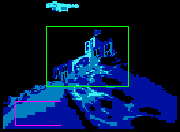
| Quadtrees are a way of breaking up an image into large blocks,
then splitting those blocks into 4 smaller blocks when required. This is intended to combine the advantages of large block sizes (Small bytesize for simple images) and the advantage of small blocks (flexibility for varied images) Suppose we want to compress this image -> |
 |
| First we split the image up into large blocks (in our example's
case 64x64) Each of these blocks will be considered |
 |
| Lets take a look at this block This block is quite varied, so we probably want to split it into four 32x32 blocks (Yellow). The TopRight block is completely empty so we'll solid fill it. The BottomLeft block is quite complex - maybe we should store it at high resolution The TopLeft and BottomRight blocks are also rather varied, so maybe these should be split into four 16x16 blocks (blue), and considered separately! |
 |
| This repeated splitting into quads is known as a quadtree. |
The compression techniques
| Because we're working on a lowly 8 bit system we won't be using
Jpeg compression To 'compress' the blocks, we'll simply store them at different resolutions Something detailed, like the castle, we'll store at high resolution. Something vague, like the mountain, we'll store at lower resolution. |
 |
| We'll use the following possible compression algorithms: 1. Store the block as as solid filled color (or transparent) 2. Store the block at 1x1 (full resolution) 3. Store the block at 1x2 (half vertical resolution - only works for 8x8 blocks) 4. Store the block at 2x2 (half resolution - only works for 8x8 blocks) 5. Store the block at 4x4 (quarter resolution - only works for 16x16 blocks) |
 |
| You'll notice most of our 'compression
algorithms' only work for 8x8 or 16x16 blocksize... we'll have
to split a block until we get to one of those sizes. This may seem wasteful, but it also has advantages: 1. We can hardcode our program to work at a fixed size to gain speed. 2. Small blocks are more likely to be repeated in other places, so we can 'reusue' the bitmap data for two small blocks. |
|
|
Don't be
surprised if the resulting images aren't so great... We're stuck
between some SUCK and a HARD place with this project! As we're compressing hundereds of frames, We need to have speed and small sizes, so we're going to have to make tough choices! The 1x2 resolution is chosen because it's easy to do on the CPC, and gives nearly as good quality as 1x1... 2x2 and 4x4 are done via lookup tables... we've covered that before. |
Making the video
| The video is split into 3 sections with 450 frames in total, and
uses palette switching for extra effect! The video is stored on a 481k CPC+ cartridge, which allowed for near instant bank switching, so no loading, and no 128k memory requirement. In theory the video could be run from 512k ram in the same way, but the memory layout would need reconfiguring. |
 |
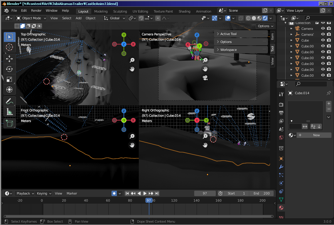
| The Scene was rendered with the open source 'Blender' 3D rendering
program. |
 |
| The video was exported as a series of PNG files. | 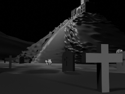 |
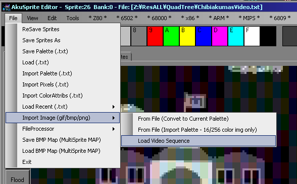
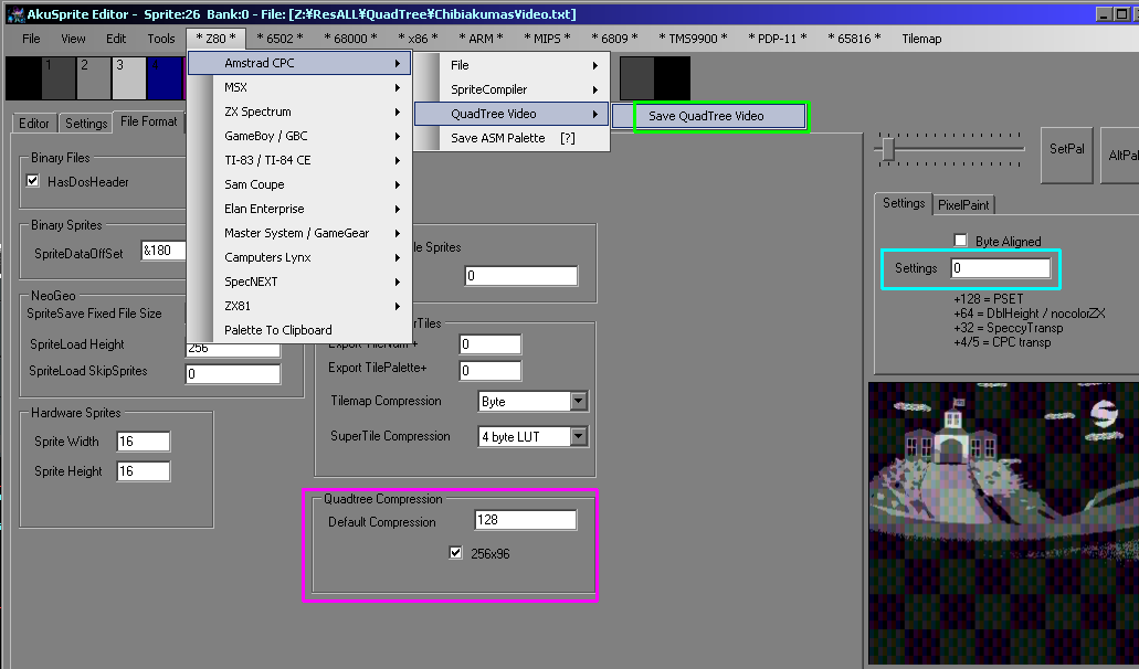
| A special function was added to Akusprite Editor to load a video
sequence. |
 |
| The video can be exported with Save
Quadtree Video The default quality setting can be set in File format... this is used to choose the compression for each block The default can be overridden on a per frame basis with the Setting option |
 |
The Quadtree routine
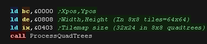
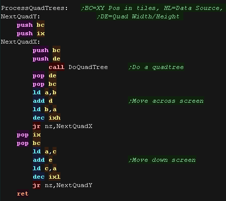
| When we want to process a
frame, we use the ProcessQuadTrees routine. This is a recursive
routine which is also used when a block is split into quads BC is the topleft corner of the block. DE is the width and height of the block (in 8 pixel blocks, so &0808 is 64x64) IX is the width and height in blocks... so &0403 is 04*64 x 03*64 = 256x192 |
 |
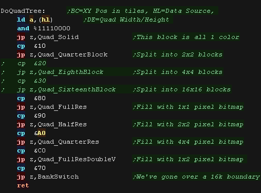
| the DoQuadTree routine will decide on the correct algorithm for
decoding the block, This routine is executed for each block in the area. |
 |
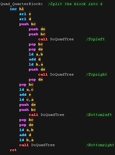
| When we want to split a block into 4, we have an alternate
version, to save a little time on loops. |
 |
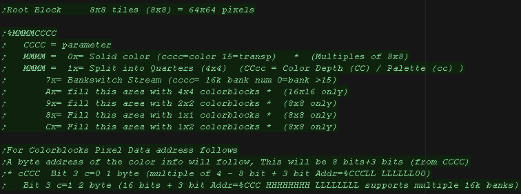
| To process a block, we read in a byte from the command datastream. The top nibble defines the block type, the purpose of the bottom nibble depends on the block type. |
 |
Solid filled block
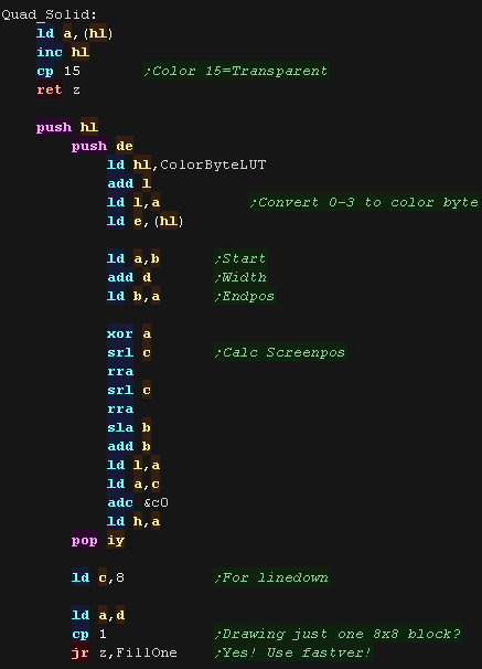
| When we want to solid fill a block we have two routines to handle
this The color to fill the block is defined by the bottom nibble of the block definition. A 'general' one for any size, and a fast '8x8 pixel' version. Color 15 is the transparent color, so if we're filling with that, then this is a block to be ignored. Otherwise we calculate the screen VRAM destination. |
 |
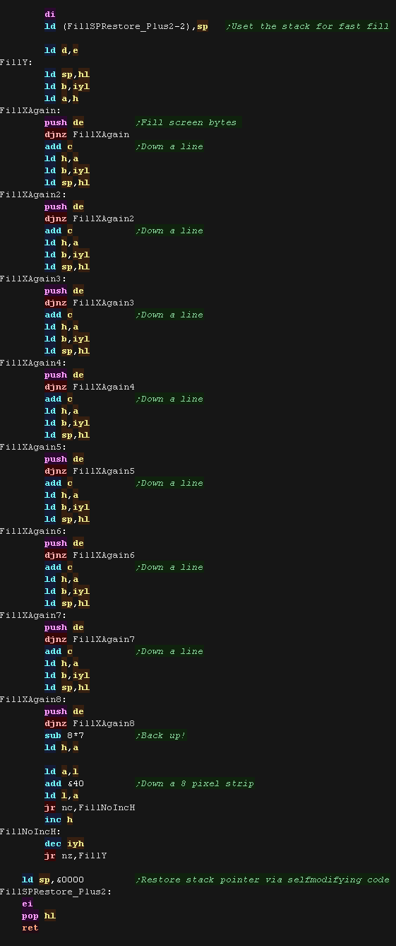
| We use PUSH commands and stack misuse to fast fill. We also do 8 consecutive lines 'unwrapped' to increase speed. Working in 8 line blocks allows us to optimize our 'nextline' routine, as 7 consecutive 'nextlines' within a block are simple, but the 8th is more complex. |
 |
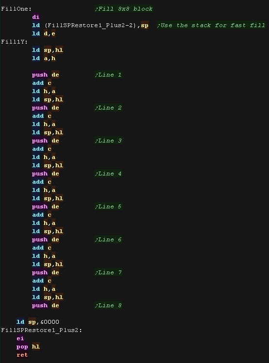
| the 8x8 routine is even simpler, as we can just do 1 push (2 bytes
- 8 pixels) per line, and not worry about getnextline |
 |
Full Resolution blocks
| Bitmap blocks use a pixel data stream (PixelBlock),
however so that repeated blocks are only stored once this is stored
separately to the command stream. The address in the bitmap stream is stored either as 11 bit, or 19 bit This means there is either one address byte, plus 3 bits from the low nibble of the data block definition, or two bytes, plus 3 bits. The bitmap data is aligned so The bottom two bits of the address are always zero, so a 2 byte address supports a range of 512k (for bank switching support) |
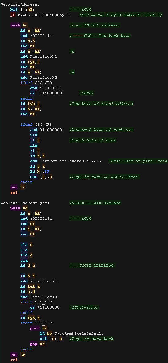 |
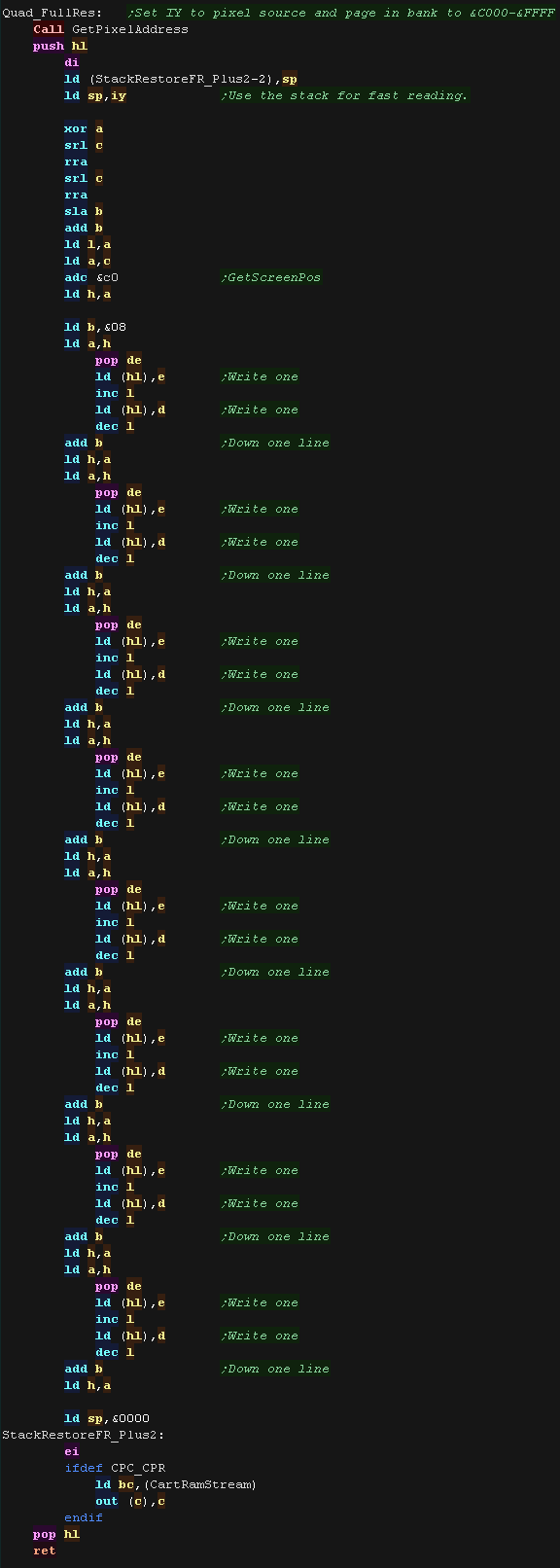
| The Fullres routine only works on 8x8 blocks, which
makes screen address adjustment simple and removes the need for
loops We use stack misuse to quickly read data in from the source bitmap. |
 |
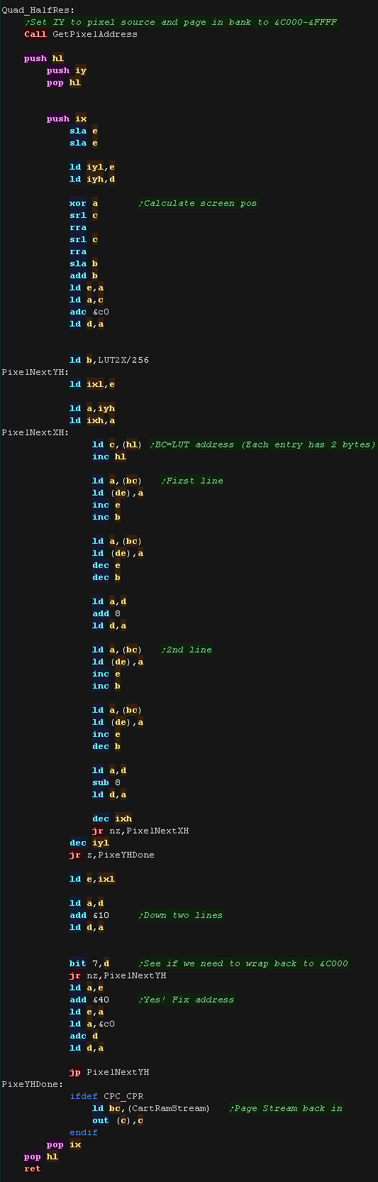
Half and Quarter Res
| The Half and Quarter resolution compressors use a
lookup table to quickly convert a byte in the stream to 2 or 4
screen bytes. This was covered previously for sprites Here is the Half res version 2 bytes are read in from the lookup table for each source byte. A source byte is loaded from the stream, and this is used as the low byte in the lookup table, the High byte is incremented to get the second destination byte. |
 |
|
Here we've
looked at the concept of Quadtrees and how the blocks are decoded
and displayed. Next time we'll take a look at the CPC+ Cartridge, and some of the tricks we've had to do to get things working! |
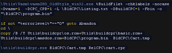
Building our cartridge
| We first compile our sourcecode to a binary file and then convert
this to a CPR using BuildCPR. Were including a modified OS,Basic and Amsdos rom which simulate a disk system using the cartridge. - Though our program doesn't technically need disk or basic support! We're using BUILDCPR to covert these to a CPR |
 |
| OS.ROM BASIC.ROM and AMSDOS.ROM were taken from the NoCart
program, however BuildCPR gives us more flexibility. However we have modified the ROM source of patchdos.asm with a new initialization routine. Our 'bootstrap' is at memory address &dc00, however it transfers itself to address &A100 so that the rom can be paged out. It pages in 3 banks of the cartridge, and copies &A000 bytes of the ROM to &0100 in ram, then executes address &0100. Our program needs to run from this address and take control! |
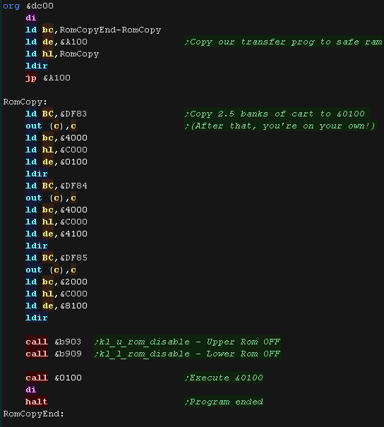 |
| Our program starts at address &100 Thanks to the bootstrap it will be running in ram! |
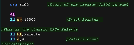 |
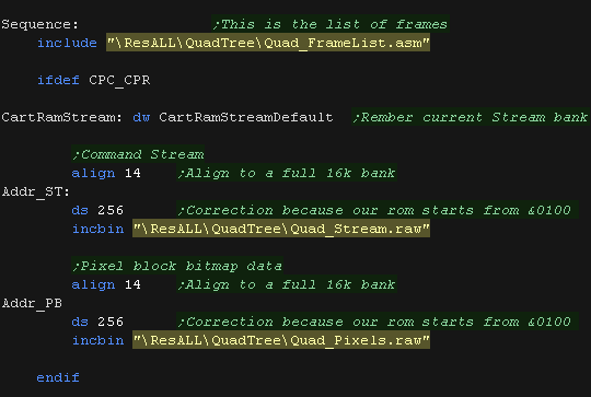
The Framelist
| AkuSprite Exports the bitmap data for the frames and the Command
Stream, However it also exports a 'template' of the image list with
pointers to the addresses of the frame data. This is intended to allow frames to be held onscreen longer, or repeated to save memory, however neither function was actually used. BUT... We did inject some 'CPC+ palette switch commands' into the stream! |
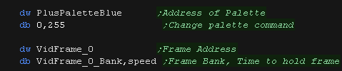  |
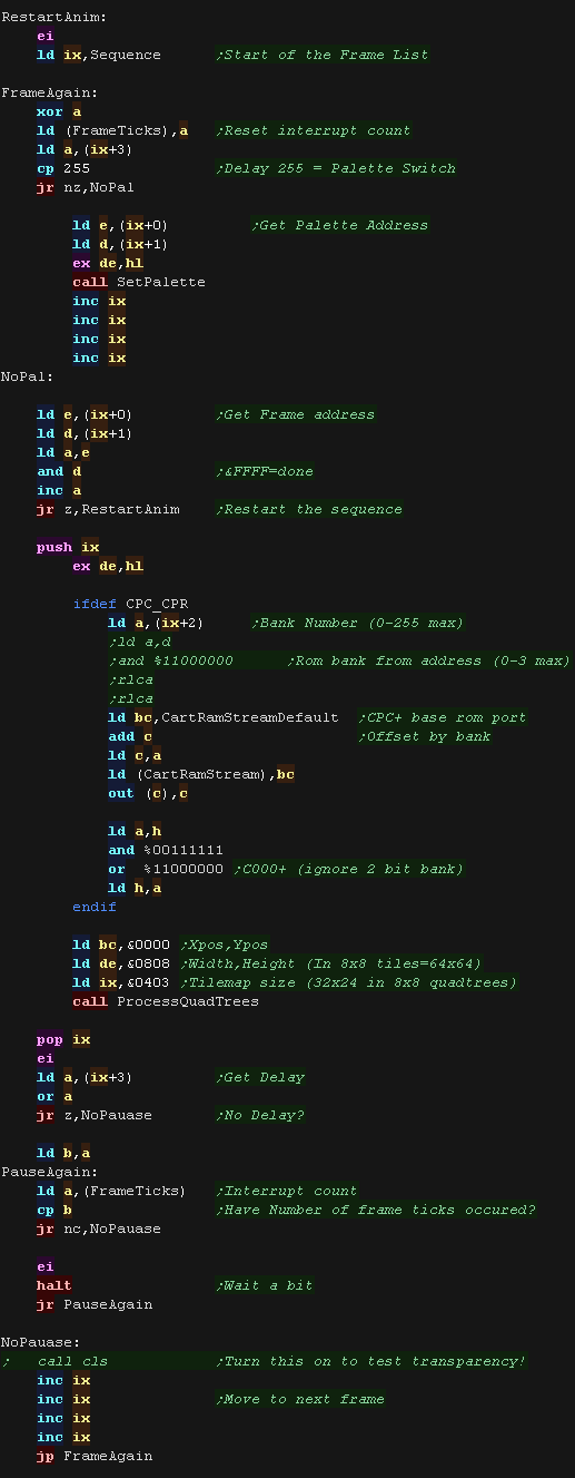
The Frame processing sequence goes through each frame in the Sequence. First it checks if the frame is a palette switch (Speed=255) if it is, the address of the palette is loaded in and switched via the CPC+ functions. Next it's checked if both bytes of the address are &FF &FF - this marks an end of stream (a real frame would never start at the end of a block!) Anything else is a legit frame, so the bank is paged in and the frame is shown. Once a frame has been shown we test the delay, and see if drawing the frame has taken longer than the delay, if not we wait a while until enough time has passed - this is to control the speed, as some frames are very slow, but others are super fast. |
 |
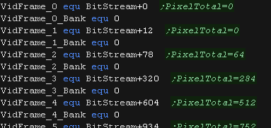
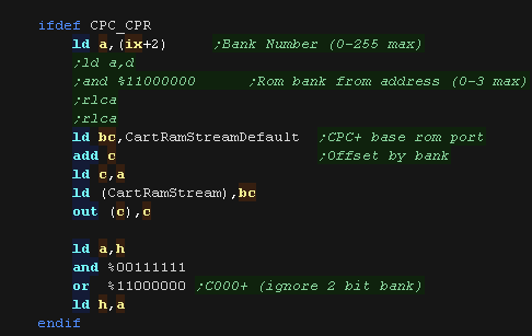
Rom Paging
| There are 3 parts to our video. 1. The Framelist - This is used for the video sequence... it's always in memory. 2. The Command Stream - This defines the blocks that make up each data... It's paged in as needed 3. The Pixel Block data - This is used for bitmap blocks, it's separate from the commands so multiple blocks can share the same bitmap data... It's paged in as needed We need to ensure 2 and 3 start in a new 16k bank... BUT we also need to offset these by 256 bytes, to compensate for the fact our program starts from address &0100, but appears in rom at the start of a bank &0000 |
 |
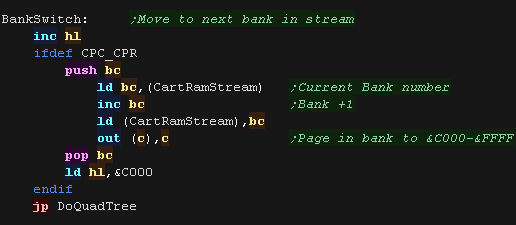
| The Frame routine includes a 1 byte 'bank number' so the correct
bank can be paged in to process the Command Stream If a frame spans over two banks, it can request a bankswitch to move to the next bank |
  |
| The Two byte addresses for Pixel blocks include a 5 bit bank number (3 low bits in the low nibble + top 2 bits in the two byte address | 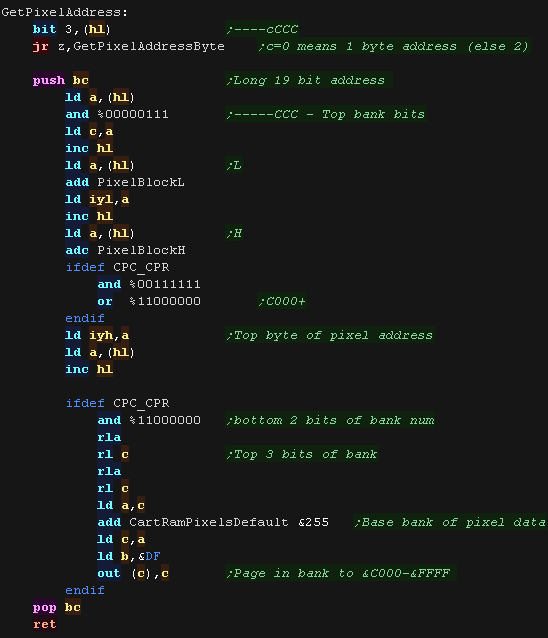 |
CPC+ Palette
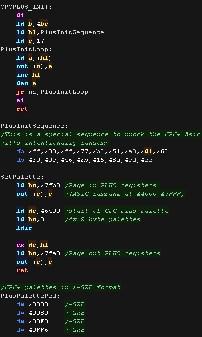
| The QuadTree video decoder
doesn't really use any CPC+ features (except rom switching) - so can
be used on a classic CPC However we use the CPC+'s more flexible palette to allow for nicer colors. |
 |
ChibiTracks for chibi beats!
| The music of the demo is basically the same theme as the original
ChibiAkumas game, however it has been converted to my new
ChibiTracks music player! ChibiTracks is a multiplatform player, which uses the ChibiSoundPro platform specific driver. We play music during the interrupt handler. |
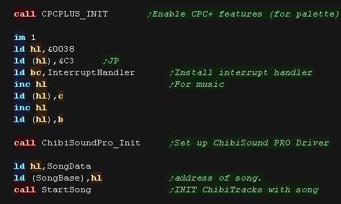 |
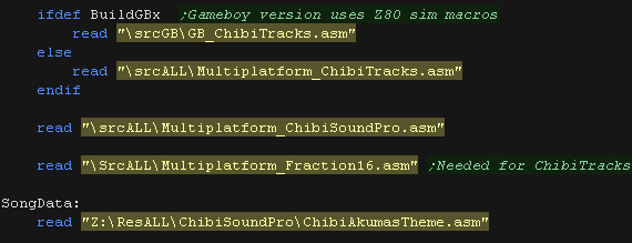
| ChibiTracks and it's requirements are included as ASM. |
 |
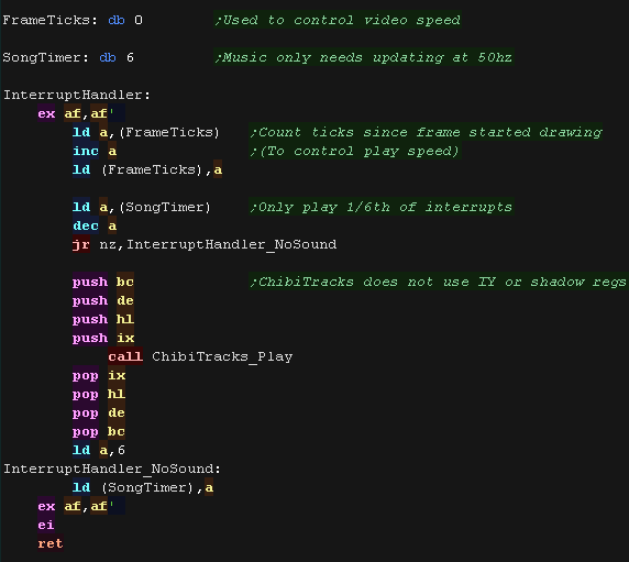
| The interrupts on the CPC occur at 300hz... but our music needs to
play at 50hz, so we skip 5/6 interrupts. Chibitracks only uses AF,BC,DE,HL and IX - it does not use IY or shadow registers! |
 |
| ChibiSound
PRO and ChibiTracks support all the Z80,6502 and 68000 systems
covered in these tutorials. But We'll take a look at it in future lessons! |
|
Our bitplane data
| We're going to compress an 'ovescan image' of 380x272. The raw image is 27,278 bytes... if we RLE compress this it would go down to 13,425 BUT... if we split it into two bitplanes and RLE compress, the image will be a total of 11,144... saving 2,281 bytes for the identical resulting picture! |
 |
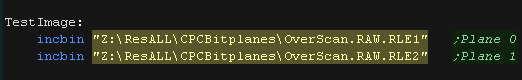
| We're going to split the image into 2 bitplanes, and also as
horizontal bytes are very likely to be different, but vertical ones
may be more similar, we'll work in 8x8 blocks. Coincidentally this is the same file format as the Gameboy uses! |
 |
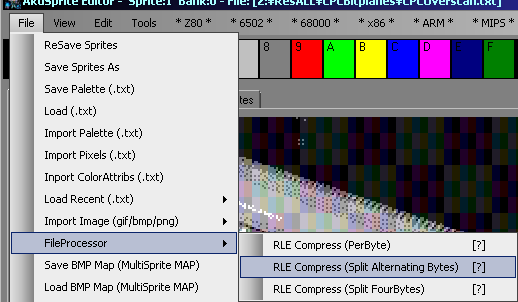
| The file needs to be RLE compressed, and split into two. Akusprite Editor has an option to do this! |
 |
| We'll include the two files in our source. |
 |
Our RLE compressor
| We're using a flexible decompressor. It uses IY as a pointer to the source file. IXL is the bytecount for RLE data (all bytes same) IXH is the bytecount for Linear data (all bytes different) BC,DE,HL and shadow regs are unused. call RLEDecompress to Start processing stream IY call RLEGetNextByte to Move to the next byte - read from (IY) to get the result |
 |
Setting up our screen
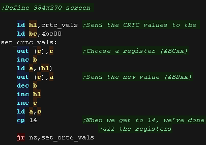
| We're going to set up the screen, we need to set up all the CRTC
registers - you can see the full list here We use port &BCxx to select register xx We use port &BDxx to set the selected register to value xx &0C/D define the base screen address, and also allow the 32k screen we need for overscan. |
 |
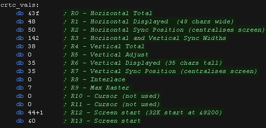
| Here are the values we're using! Our screen is huge, and spans two
16k banks... Bank 1 is &8200-&BFFF Bank 2 is &C000-&FFFF Memory <&8200 is free, so we'll use it for our stack! Memory &0000-&3FFF is free so we can use IM1, Memory &4000-&7FFF is free so we can use ram bank switching but there's a slight memory 'gap' between them we'll have to deal with! |
 |
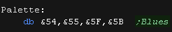
| We're going direct to the hardware to set our colors. We use port &7Fxx to do this. We need to use hardware color numbers |
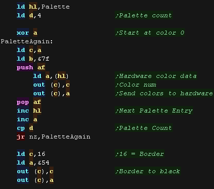  |
Drawing our image
| We XOR in our image data, so we clear the screen first | 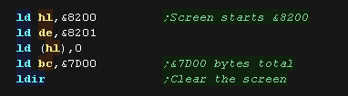 |
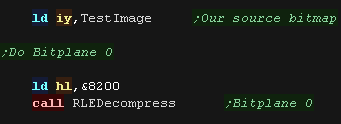
| We point IY to our source data, and execute RLEDecompress to
initialize the RLE data stream. HL points to the VRAM destination |
 |
| We work in 8x8 tiles. First we go across the screen - 48 tiles total (384 pixels) Then we go down the screen - 34 strips total (272 lines) |
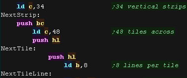 |
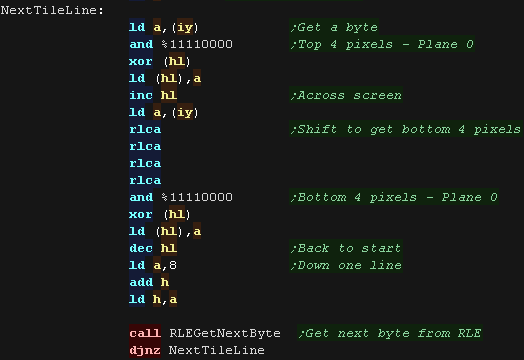
| We'll do bitplane 0 - The top 4 bits of a byte are bitplane 0 in
mode 1 We read a byte from the RLE stream (IY) We take the top 4 pixels, mask bitplane 0 and write them to the screen... we move 1 byte to the right We take the bottom 4 pixels, mask bitplane 0 and write them to the screen... we move back left we then move down 1 line (by adding &0800 to HL) and repeat. RLEGetNextByte moves IY to the next byte |
 |
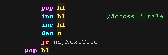
| We move across the screen 1 tile (2 bytes) and repeat until we've
done an entire horozontal strip of tiles. |
 |
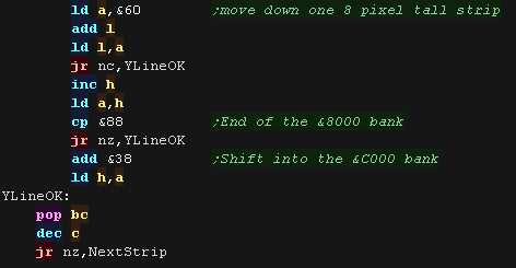
| We need to move down 1 strip, and when we get to the end of the
&8000-&BFFF bank, we manually step into the &C000 bank We repeat until bitplane 0 is entirely drawn |
 |
| We now do the same for bitplane 1 - The bottom 4 bits of a byte are bitplane 0 in mode 1 | 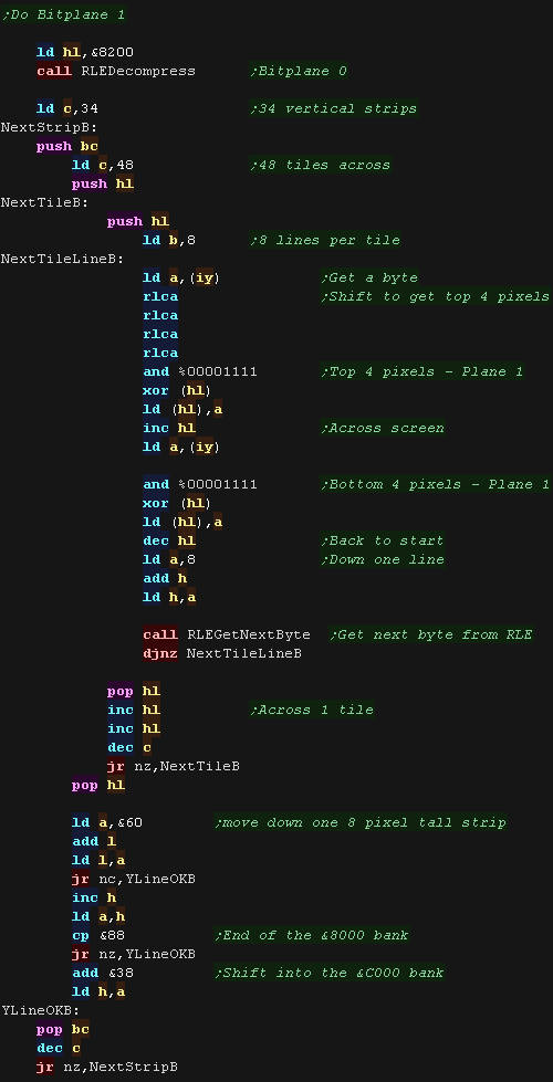 |
|
This example was
just an experiment in saving a little memory by re-organizing
data. Take a look at the 10k subs example for more impressive 'lossy' compression - of course the video in that example is basically a sequence of images. |

|
Lesson
P69 - ChibiSound PRO on the CPC, MSX and Spectrum (128 - AY) Lets take another look at sound!... we'll make an improved multiplaform sound driver for music! |
 |
 CPC_V1_ChibiSoundPro.asm
|
 |
ChibiSound PRO!
ChibiSound is the sound driver that handles the particularities of a system, there is typically one driver per system, though the CPC and MSX drivers are essentially identical except for the AY register setting routines.
The original 'ChibiSound' gave us one channel, one Volume bit, six pitch bits, and the ability to turn noise on. Pitches were not matched across systems, so sound 32 won't sound the same on all systems.
The updated 'ChibiSound Pro' gives us all the channels provided by the hardware, 8 volume bits, 16 pitch bits, and the ability to turn noise on. Pitches were not matched across systems, however the 'ChibiOctave' lookup table provides values which ARE matched across all systems.
ChibiSound PRO is essentially a reduced subset of AY functionality, and was designed on the Z80 - it's 'PRO' suffix is a parody of the 'SoundBlaster PRO' - which could only do 8 bit sound so wasn't up to professional standards! (neither is ChibiSound PRO)
ChibiSound PRO provides a standard interface to the underlying hardware, it allows the following features to be set for each channel on the underlying hardware:
| Function |
Register |
Notes: |
| Channel Number (bit 0-6) Noise On/Off (bit 7) |
L | Multiple channels can be supported, but on single channel systems
only Channel 0 will be sure to play. If possible Channel 0 will be a center channel, Channels 1+ may be left/right Noise bit turns the noise effect on (1) or off (0) - this can be set on any channel, if the underlying hardware only supports one noise channel, this will be resolved by the driver. |
| Volume | H | Set volume of the channel (0-255). Higher numbers are louder. O is off |
| Pitch | DE | Set the pitch of the channel (0-65535). Higher numbers are higher
pitch. Using DE does not standardize the resulting pitch - however a 'Lookup table' of notes 'ChibiOctave' provides a standardized way of getting the correct DE value to get a pitch correct note on the platform. |
| The
new driver is a big improvement on the old one but doesn't really
deserve the PRO suffix! It's a parody of the early 'Soundblaster Pro' sound cards, which could only do 8 bit digital sound, so weren't really of 'pro spec' either! |
|
AY Sound Chip
The AY uses a series of 8 bit registers to control the 3 sound channels.
To set a register, we must first select the register number by writing a byte to $FF8800, then send the byte of data to $FF8802
| Register | Meaning | Bit Meaning | Details |
| 0 | Tone Pitch L - Channel A | LLLLLLLL | Lower value = Higher pitch |
| 1 | Tone Pitch H - Channel A | ----HHHH | Lower value = Higher pitch |
| 2 | Tone Pitch L - Channel B | LLLLLLLL | Lower value = Higher pitch |
| 3 | Tone Pitch H - Channel B | ----HHHH | Lower value = Higher pitch |
| 4 | Tone Pitch L - Channel C | LLLLLLLL | Lower value = Higher pitch |
| 5 | Tone Pitch H - Channel C | ----HHHH | Lower value = Higher pitch |
| 6 | Noise Generator | ---NNNNN | Higer = Faster noise |
| 7 | Mixer | --NNNTTT | N=Noise T=Tone (Channel --CBACBA 1=mute 0=normal) |
| 8 | Amplitude - Channel A | ---EVVVV | E=Envelope (1=Enabled) VVVV=Volume |
| 9 | Amplitude - Channel B | ---EVVVV | E=Envelope (1=Enabled) VVVV=Volume |
| 10 | Amplitude - Channel C | ---EVVVV | E=Envelope (1=Enabled) VVVV=Volume |
| 11 | Envelope L (Volume over time) | LLLLLLLL | Lower=Faster Envelope |
| 12 | Envelope H (Volume over time) | HHHHHHHH | Lower=Faster Envelope |
| 13 | Envelope Selection | ----EEEE | Envelope number (See PDF) |
For more details, please see the AY
sound chip PDF
| Only the way we send data to the AY chip changes on each of the 3 platforms, the main sound code is identical! |  |
The ChibiSoundPRO source - All platforms
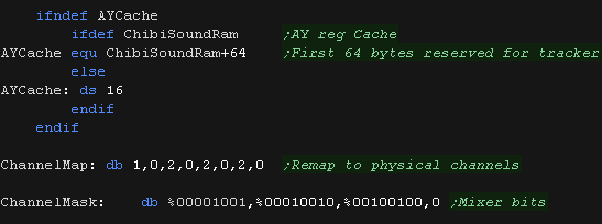
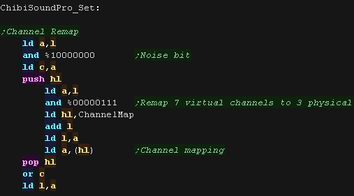
| We need some parameters! We have some cache ram to keep track of the AY register settings We have a 'ChannelMap' which allows us to simulate 8 possible virtual channels We have a 'ChannelMask' to get the bit pattern for the channels Mixer settings |
 |
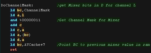
| DoChannelMask Will get the settings to set the current channels
mixers bits. it also points Point BC to previous mixer value in ram, in case we need it! |
 |
| ChibiSoundPro_Init will set things up, loading the default 'silent' value into the mixer cache | 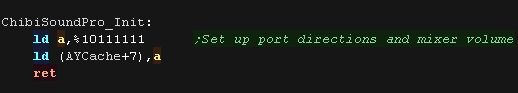 |
| ChibiSoundPro_Set will configure our sound
channel H=Volume (0-255) L=Channel Num (0-127 unused channels will wrap around) / Top Bit=Noise DE=Pitch (0-65535) The channel number can be up to 128, so we remap it to channels 0-2 with the ChannelMap table |
 |
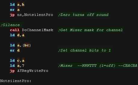
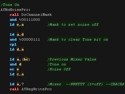
| Now we check the volume - if it's zero we want to silence the
channel. We do this by setting the channels Noise and Tone bits to 1 in the mixer (reg 7) |
 |
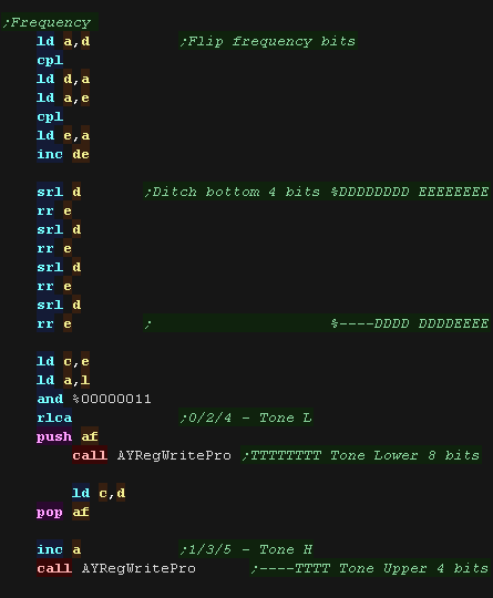
| We need to send the 12 bit frequency to the two registers for the
channel Channel 0 uses 0/1 Channel 1 uses 2/3 Channel 2 uses 4/5 We also need to flip the bits, as chibiSoundPro uses the value &FFFF as the highest frequency, but the AY uses &-000 |
 |
| If we need to make a noise, we need to clear the channel tone bit
in the mixer, and clear the noise bit to turn noise on We also set the 5 bit noise frequency in reg 6 |
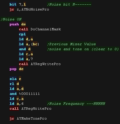 |
| If we want to make a tone... we need to set the noise bit (turning noise off) we need to clear the tone bit (turning tone on) |
 |
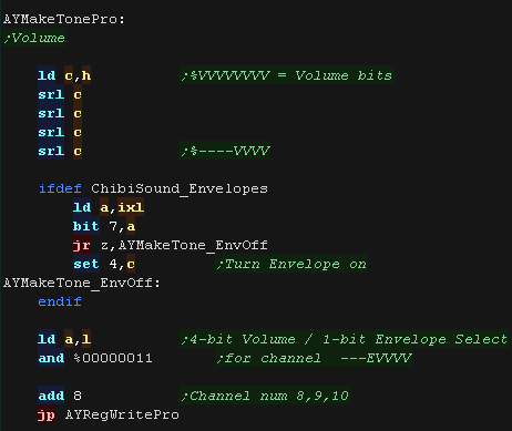
| Finally we set the volume. The AY uses a 4 bit volume, and this is set for the 3 channels with Reg 8/9/10 |
 |
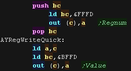
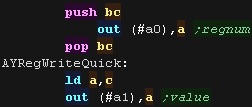
Platform Specific AYRegWritePro
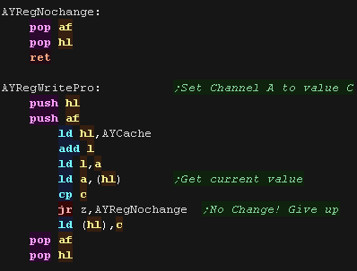
| AYRegWritePro will set AY register A to value C it uses AYCache to avoid writing values which are unchanged to the hardware. |
 |
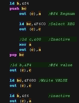
| On the CPC we have a rather odd sequence of
commands! this is because the AY chip is linked through the keyboard
hardware. |
 |
| on the Spectrum we use ports &FFFD and
&BFFD to select the register and send the new value |
 |
| on the MSX we use ports &A0 and &A1 |
 |
| View Options |
| Default Dark |
| Simple (Hide this menu) |
| Print Mode (white background) |
| Top Menu |
| ***Main Menu*** |
| Youtube channel |
| Patreon |
| Introduction to Assembly (Basics for absolute beginners) |
| Amazon Affiliate Link |
| AkuSprite Editor |
| ChibiTracker |
| Dec/Bin/Hex/Oct/Ascii Table |
| Alt Tech |
| Archive.org |
| Bitchute |
| Odysee |
| Rumble |
| DailyMotion |
| Please note: I wlll upload more content to these alt platforms based on the views they bring in |
| 68000 Content |
| ***68000 Tutorial List*** |
Learn 68000 Assembly  |
| Hello World Series |
| Platform Specific Series |
| Simple Samples |
| Grime 68000 |
| 68000 Downloads |
| 68000 Cheatsheet |
| Sources.7z |
| DevTools kit |
| 68000 Platforms |
| Amiga 500 |
| Atari ST |
| Neo Geo |
| Sega Genesis / Mega Drive |
| Sinclair QL |
| X68000 (Sharp x68k) |
| 8086 Content |
| Learn 8086 Assembly |
| Platform Specific Series |
| Hello World Series |
| Simple Samples |
| 8086 Downloads |
| 8086 Cheatsheet |
| Sources.7z |
| DevTools kit |
| 8086 Platforms |
| Wonderswan |
| MsDos |
| ARM Content |
| Learn ARM Assembly |
| Learn ARM Thumb Assembly |
| Platform Specific Series |
| Hello World |
| Simple Samples |
| ARM Downloads |
| ARM Cheatsheet |
| Sources.7z |
| DevTools kit |
| ARM Platforms |
| Gameboy Advance |
| Nintendo DS |
| Risc Os |
| Risc-V Content |
| Learn Risc-V Assembly |
| Risc-V Downloads |
| Risc-V Cheatsheet |
| Sources.7z |
| DevTools kit |
| MIPS Content |
| Learn Risc-V Assembly |
| Platform Specific Series |
| Hello World |
| Simple Samples |
| MIPS Downloads |
| MIPS Cheatsheet |
| Sources.7z |
| DevTools kit |
| MIPS Platforms |
| Playstation |
| N64 |
| PDP-11 Content |
| Learn PDP-11 Assembly |
| Platform Specific Series |
| Simple Samples |
| PDP-11 Downloads |
| PDP-11 Cheatsheet |
| Sources.7z |
| DevTools kit |
| PDP-11 Platforms |
| PDP-11 |
| UKNC |
| TMS9900 Content |
| Learn TMS9900 Assembly |
| Platform Specific Series |
| Hello World |
| TMS9900 Downloads |
| TMS9900 Cheatsheet |
| Sources.7z |
| DevTools kit |
| TMS9900 Platforms |
| Ti 99 |
| 6809 Content |
| Learn 6809 Assembly |
| Learn 6309 Assembly |
| Platform Specific Series |
| Hello World Series |
| Simple Samples |
| 6809 Downloads |
| 6809/6309 Cheatsheet |
| Sources.7z |
| DevTools kit |
| 6809 Platforms |
| Dragon 32/Tandy Coco |
| Fujitsu FM7 |
| TRS-80 Coco 3 |
| Vectrex |
| 65816 Content |
| Learn 65816 Assembly |
| Hello World |
| Simple Samples |
| 65816 Downloads |
| 65816 Cheatsheet |
| Sources.7z |
| DevTools kit |
| 65816 Platforms |
| SNES |
| eZ80 Content |
| Learn eZ80 Assembly |
| Platform Specific Series |
| eZ80 Downloads |
| eZ80 Cheatsheet |
| Sources.7z |
| DevTools kit |
| eZ80 Platforms |
| Ti84 PCE |
| IBM370 Content |
| Learn IBM370 Assembly |
| Simple Samples |
| IBM370 Downloads |
| IBM370 Cheatsheet |
| Sources.7z |
| DevTools kit |
| Super-H Content |
| Learn SH2 Assembly |
| Hello World Series |
| Simple Samples |
| SH2 Downloads |
| SH2 Cheatsheet |
| Sources.7z |
| DevTools kit |
| SH2 Platforms |
| 32x |
| Saturn |
| PowerPC Content |
| Learn PowerPC Assembly |
| Hello World Series |
| Simple Samples |
| PowerPC Downloads |
| PowerPC Cheatsheet |
| Sources.7z |
| DevTools kit |
| PowerPC Platforms |
| Gamecube |
| Work in Progress |
| ChibiAndroids |
| Misc bits |
| Ruby programming |
Buy my Assembly programming book
on Amazon in Print or Kindle!


Available worldwide!
Search 'ChibiAkumas' on
your local Amazon website!
Click here for more info!


Buy my Assembly programming book
on Amazon in Print or Kindle!
Available worldwide!
Search 'ChibiAkumas' on
your local Amazon website!
Click here for more info!
Buy my Assembly programming book
on Amazon in Print or Kindle!
Available worldwide!
Search 'ChibiAkumas' on
your local Amazon website!
Click here for more info!