

Learn Multi platform 6502 Assembly Programming... For Monsters!
Platform Specific Lessons
Platform Specific Series - Now we
know the basics, lets look at the details of the platforms we're covering!

Color
Palette
| The Nes palette is slightly odd
compared to RGB systems, you can see how the HEX values map to
colors in the chart to the right-> Each tile has 4 colors*, and you can have 4 separate palettes for tiles... and a separate 4 for sprites... this makes a total of 32 color definitions for tiles and sprites combined * Though the background colors are common to all sprites. |
|
||||||||||||||||||||||||||||||||||||||||||||||||||||||||||||||||
| Our Tutorials use a common format
on all platforms, where each channel is defined by one nibble in
$-GRB format... Because this doesn't easily map to the Nes palette, we'll convert it using a Lookup table of 3x3x3 size, so RGB values will go from 0-2 |
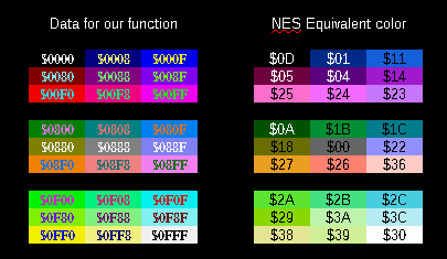 |
| The NES
palette is a bit rigid, and doesn't really map to RGB very
well, but we've done what we can! If you don't like the mappings here, you can change the Lookup Table, or write your own native code. |
 |
Vram Layout
| While Pattern data is defined by
the Name Table, the Attribute Table defines the Color By default the NES has too little VRAM to use Name/Attrib Table 2 & 3 Specify a memory address by writing the byte pair to $2006... HIGH BYTE FIRST... (Big Endian) NOTE: Writing to VRAM outside of VBLANK will cause problems... also note, selecting an address resets PPUSCROLL EG, lets point to $3F00... and write $11 to the first palette entry! lda #$3F ;High byte sta $2006 ;Send to vram select lda #$00 ;Low byte sta $2006 ;Send to vram select lda #$11 ;New value sta $2007 ;Send to write data |
* Extra Ram Only |
||||||||||||||||||||||||||||||||||||||||||
| Each palette on the NES has 3 colors -Background Color 0 is a common background color, and Color 0 in sprites transparent |
|
||||||||||||||||||||||||||||||||||||||||||
| The NES Name Table defines the Tilemap's patterns... one byte
per 8x8 tile defines the number of the tile... the name table is
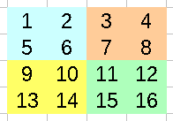
32x30 tiles in size, so spans from $2000-$23BF Note: Name Table 2,3 ($2800-$3000) are not available on an standard NES , they will only be available if your cartridge has Extra Ram! Color's are defined by the 'Attribute table'... effectively, each square block of 2x2 tiles (16x16 pixels) have to use the same color palette... and each block of 4x4 tiles (32x32 pixels) are defined by a single byte (2 bits per block - for 4 possible palettes) Lets take the example to the right, with different 16 tiles making up a grid of 32x32 pixels- each areas palette would be defined by a single byte in the way below:
|
 |
 |
Unfortunately on the
NES, although our tiles are 8x8 pixel, our palette is defined at
a 16x16 level You'll notice objects in NES games (Such as ? blocks in mario) are usally 16x16 to ensure this isn't a problem. |
Our
Code
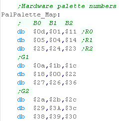
| We're going to use a 3x3x3
table of color conversions to convert our one nibble per
channel $-GRB definition to something valid for the NES Offset=(G*9)+(R*3)+B to calculate the color of the equivalent GRB color for the NES |
 |
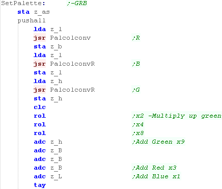
| When we call our SetPalette
function, we set A to the palette entry, and z_h and z_l as
the word defining the new color (in $-GRB format) We then want to calculate the palette entry, using the formula we just mentioned... We're going to use two functions One is 'PalcolConv' - which will take a high nibble, and convert it to a value 0-2.... The other is PalConvR - which will take the low nibble and do the same.... Once we've calculated the offset, we store it into Y |
 |
| We're going to need to load in the address of the lookup table into z_hl | 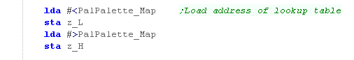 |
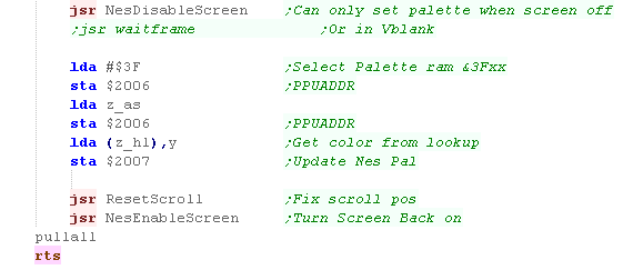
| We need to work out the correct
address to write to within the GTIA ($D016-D01A on the Atari
800 or $C016-C01A on the 5200) Color 0's address is $D01A Color 1's address is $D016 Color 2's address is $D017 Color 3's address is $D018 Once we've calculated the palette address to write to, we just output the new color we got from the lookup table to the destination address |
 |
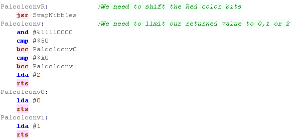
| Our palette conversion routines
use the following RGB conversions to convert a nibble to a
value 0-2 0-4...0 5-9...1 10-15...2 |
 |
 |
Lesson
P22 - Palette Definitions on the SNES / Super Famicom The Snes has 256 onscreen colors, and a superb 5 bits per channel RGB palette definition... lets learn how to use it! |
 |
 BmpTest.asm
|
|
 |
| Two ports are used to define the color on the SNES, the first
takes a single byte and selects the color we want to change, the second takes two bytes, and defines the new RGB color for that entry. |
|
||||||||||||||||||||||||||||||||||||||||||||||||||||||
| The 256 colors make up 16
palettes... the first 8 are used by Background patterns... the
second 8 are used by Sprites |
|
||||||||||||||||||||||||||||||||||||||||||||||||||||||
| In these tutorials, we a common format using one nibble per
color channel in the format $-GRB... The SNES uses 5 bits per channel in the format %-BBBBBGG GGGRRRRR We will need to convert our format to the correct format for the SNES! |
|
| The 255 onscreen
colors of the SNES are split between the Backgrounds and
Sprites, but the code will look at today will set background
and sprite colors at the same time. This will make things easier, and as we've only got 16 colors on most systems, we won't miss the extra colors in these tutorials! |
 |
Our
Code
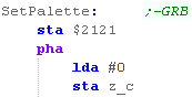
| When we call our SetPalette function, we set A to the palette
entry, and z_h and z_l as the word defining the new color (in
$-GRB format) We define the Color we're going to change by storing A in port $2121 We're going to use z_bc as a 'buildup' for the SNES format, so we need to clear z_c |
 |
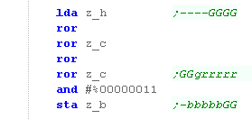
| We're going to first shift the Green component... We only have 4 bits in our definition, but the SNES uses 5, we'll shift two of the bits to the left into z_c, and store the top two bits into z_b |
 |
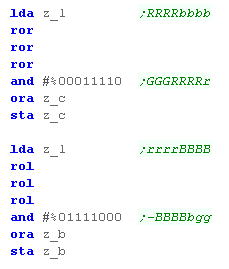
| We're going to shift the Red and
Blue bits as well, the correct format for the SNES is now in z_b and z_c |
 |
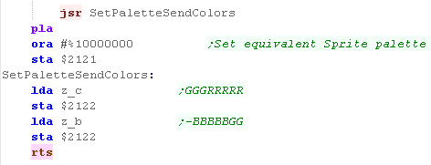
| To set the color we write the Low
byte from z_b to $2122, then we write the High byte from z_c
also to $2122 Once we've done the main color, we add 128 - and set the equivalent sprite color to the same color. |
 |

 |
In these tutorials we will write a driver
called 'ChibiSound' - it takes a single byte in the
accumulator, in the format %NVPPPPPP where N=Noise, V=Volume
and P=Pitch. This allows our multiplatform games to make sound effects in a similar way on all the systems. |
Pokey Ports
Sound on the Atari is handled by the POKEY
chip, it's address varies depending on if we're using an atari 800 or
5200.
There are 4 sound channels, each takes a Frequency from 0-255, a Volume 0-15 (0=lowest), and a 'Noise' nibble...
The noise setting will define the sound
type, a setting of %1010 is a square wave, a setting of %0000 is
distortion
| Group | Name | Description | Address A80 | Address A52 | Bits | Meaning |
| POKEY | AUDF1 | Audio frequency 1 control | $D200 | $E800 | FFFFFFFF | F=Frequency |
| POKEY | AUDC1 | Audio channel 1 control | $D201 | $E801 | NNNNVVVV | N=Noise V=Volume |
| POKEY | AUDF2 | Audio frequency 2 control | $D202 | $E802 | FFFFFFFF | F=Frequency |
| POKEY | AUDC2 | Audio channel 2 control | $D203 | $E803 | NNNNVVVV | N=Noise V=Volume |
| POKEY | AUDF3 | Audio frequency 3 control | $D204 | $E804 | FFFFFFFF | F=Frequency |
| POKEY | AUDC3 | Audio channel 3 control | $D205 | $E805 | NNNNVVVV | N=Noise V=Volume |
| POKEY | AUDF4 | Audio frequency 4 control | $D206 | $E806 | FFFFFFFF | F=Frequency |
| POKEY | AUDC4 | Audio channel 4 control | $D207 | $E807 | NNNNVVVV | N=Noise V=Volume |
| POKEY | AUDCTL | general audio control | $D208 | $E808 | N1234HHS | N=Noise bit depth 1234=Channel Clocks HH=highpass filters S=main clockspeed |
Writing Chibi Sound!
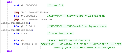
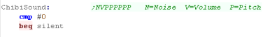
| Lets write ChibiSound... First we need to check if the value we've been passed is zero - if it is, then we'll use this as the volume and write it to reg 1 of the POKEY... Since the POKEY is at a different place on the different Atari's we use a symbol definition which will point to $D200 or $E800, and add the value of the register we want to change, so $D201 would become POKEY+$01 |
 |
| First we need to decide what kind of sound we want to make, if
the top bit is 1, then we want to make a noise! We make a noise by setting the top nibble of POKEY+1 to %0000 .... we make a square wave with %1010 The same register also handles the volume with the bottom nibble, we have only one volume bit in the Chibisound byte, so we set the lowest 3 bits to 1... We store the result in z_as for after we've worked out the volume. Finally we write Zero to POKEY+8... this sets up all the pokey settings for our sound to play |
 |
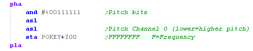
| OK, lets set the pitch of the sound... We have 6 pitch bits, but we rotate them to the left, so we're setting a value 0-252 We write this to POKEY+0 to set Channel 1's pitch/Frequency |
 |
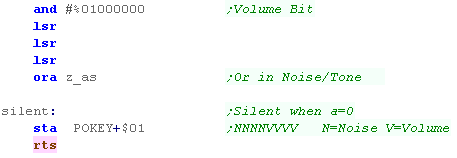
| Finally let's get the Volume... we take the one volume bit and
shift it to the top of the low nibble... We then OR in the noise on/off we stored in z_as, and write it to POKEY+1 (this is where we jumped to if A was 0 at the start) |
 |

 |
The Sound on the Atari Lynx is odd...while it's very capable, compared to other systems it's very hard to understand!...Fortunately if we ignore the documentation, and just use some 'basic code' we can get some stuff working easily! |
Sound on the Atari Lynx
The sound ports are memory mapped, there are
4 channels in total.
Each Channel links to a timer source,
Channel 0 links to 'Timer 7'... Channel 1 links to 0, Channel 2 links to
1, Channel 3 links to 2,
| From | To | Name | Description | Bits | Meaning |
| FD1C | FD1F | TIMER7 | Timer Channel 7 and mag1b | ||
| FD20 | FD20 | VOL | Audio Channel 0 � 2�s compliment Volume control | -VVVVVVV | V=Volume (0-127) |
| FD21 | FD21 | FEEDBACK | Audio Channel 0 � Shift register feedback enable | FFFFFFFF | Effective
sound of instrument ($10=Square Tone / $90=Noise) |
| FD22 | FD22 | RAW | Audio Channel 0 � Audio Output Value (Raw Data) | Constantly changes | |
| FD23 | FD23 | SHIFTL | Audio Channel 0 � Lower 8 bits of shift register | SSSSSSSS | Shift Regsiter L |
| FD24 | FD24 | FREQ | Audio Channel 0 � Audio Timer Backup Value | TTTTTTTT | T=Timer (effectively Frequency) |
| FD25 | FD25 | CONTROL | Audio Channel 0 � Audio Control Bits | FTIRCKKK | F=Feedback bit 7 , reset Timer done, enable Integrate, enable Reload enable Count, clocK select |
| FD26 | FD26 | COUNT | Audio Channel 0 � Audio Counter | Constantly changes | |
| FD27 | FD27 | OTHER | Audio Channel 0 �Other Audio Bits | SSSS-CBB | S=Shift Register H, C=Clock state B=Borrow |
| FD28 | FD28 | VOL | Audio Channel 1 � 2�s compliment Volume control | -VVVVVVV | V=Volume (0-127) |
| FD29 | FD29 | FEEDBACK | Audio Channel 1 � Shift register feedback enable | FFFFFFFF | Effective pitch of instrument |
| FD2A | FD2A | RAW | Audio Channel 1 � Audio Output Value (Raw Data) | Constantly changes | |
| FD2B | FD2B | SHIFTL | Audio Channel 1 � Lower 8 bits of shift register | SSSSSSSS | Shift Regsiter L |
| FD2C | FD2C | FREQ | Audio Channel 1 � Audio Timer Backup Value | TTTTTTTT | T=Timer (effectively Frequency) |
| FD2D | FD2D | CONTROL | Audio Channel 1 � Audio Control Bits | FTIRCKKK | F=Feedback bit 7 , reset Timer done, enable Integrate, enable Reload enable Count, clocK select |
| FD2E | FD2E | COUNT | Audio Channel 1 � Audio Counter | Constantly changes | |
| FD2F | FD2F | OTHER | Audio Channel 1 �Other Audio Bits | SSSS-CBB | S=Shift Register H, C=Clock state B=Borrow |
| FD30 | FD30 | VOL | Audio Channel 2 � 2�s compliment Volume control | -VVVVVVV | V=Volume (0-127) |
| FD31 | FD31 | FEEDBACK | Audio Channel 2 � Shift register feedback enable | FFFFFFFF | Effective pitch of instrument |
| FD32 | FD32 | RAW | Audio Channel 2 � Audio Output Value (Raw Data) | Constantly changes | |
| FD33 | FD33 | SHIFTL | Audio Channel 2 � Lower 8 bits of shift register | SSSSSSSS | Shift Regsiter L |
| FD34 | FD34 | FREQ | Audio Channel 2 � Audio Timer Backup Value | TTTTTTTT | T=Timer (effectively Frequency) |
| FD35 | FD35 | CONTROL | Audio Channel 2 � Audio Control Bits | FTIRCKKK | F=Feedback bit 7 , reset Timer done, enable Integrate, enable Reload enable Count, clocK select |
| FD36 | FD36 | COUNT | Audio Channel 2 � Audio Counter | Constantly changes | |
| FD37 | FD37 | OTHER | Audio Channel 2 �Other Audio Bits | SSSS-CBB | S=Shift Register H, C=Clock state B=Borrow |
| FD38 | FD38 | VOL | Audio Channel 3 � 2�s compliment Volume control | -VVVVVVV | V=Volume (0-127) |
| FD39 | FD39 | FEEDBACK | Audio Channel 3 � Shift register feedback enable | FFFFFFFF | Effective pitch of instrument |
| FD3A | FD3A | RAW | Audio Channel 3 � Audio Output Value (Raw Data) | Constantly changes | |
| FD3B | FD3B | SHIFTL | Audio Channel 3 � Lower 8 bits of shift register | SSSSSSSS | Shift Regsiter L |
| FD3C | FD3C | FREQ | Audio Channel 3 � Audio Timer Backup Value | TTTTTTTT | T=Timer (effectively Frequency) |
| FD3D | FD3D | CONTROL | Audio Channel 3 � Audio Control Bits | FTIRCKKK | F=Feedback bit 7 , reset Timer done, enable Integrate, enable Reload enable Count, clocK select |
| FD3E | FD3E | COUNT | Audio Channel 3 � Audio Counter | Constantly changes | |
| FD3F | FD3F | OTHER | Audio Channel 3 �Other Audio Bits | SSSS-CBB | S=Shift Register H, C=Clock state B=Borrow |
| FD40 | FD40 | ATTENREG0 | LLLLRRRR � Audio Attenuation | ||
| FD41 | FD41 | ATTENREG1 | LLLLRRRR � Audio Attenuation | ||
| FD42 | FD42 | ATTENREG2 | LLLLRRRR � Audio Attenuation | ||
| FD43 | FD43 | ATTENREG3 | LLLLRRRR � Audio Attenuation | ||
| FD44 | FD44 | MPAN | Stereo attenuation selection | ||
| FD50 | FD50 | MSTEREO | Stereo disable | LLLLRRRR | 0=all on 255=all off |
Sfx with Chibisound!
| These tutorials use a sound 'driver' called ChibiSound, Chibisound uses a single byte parameter in the Accumulator, and provides 64 different pitches, in low or high volume with either tones or noise. Sending a value of 0 mutes sound, all other values make a tone... Chibisound is intended to make it simple to have SFX in multiplatform games and was used in Grime Z80 and Grime 6502 |
|
Writing Chibi Sound!
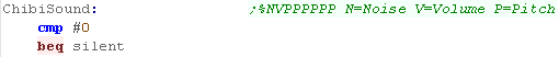
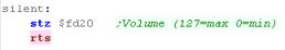
| Lets start writing ChibiSound! First we need to check if the Accumulator is zero, if it is, then we need to turn off sound. If it is, then we just need to set the volume to zero, by writing 0 to $FD20 (Channel 0 Volume) |
  |
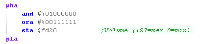
| Otherwise We need to set a volume - the Lynx needs a volume of
0-127 (7 bits)... We only have one bit for our volume in the accumulator, so we set the other six bits to 1, We write the result to $FD20 (Channel 0 Volume) |
 |
| Next we need to set the pitch... we have 6 bits in our definition, and we write these to $FD24 | 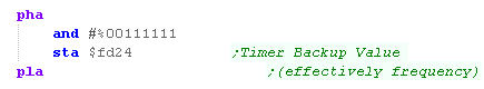 |
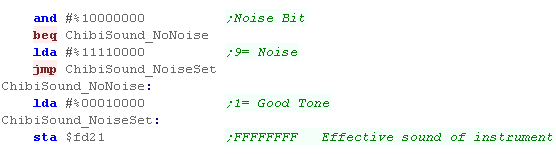
| Our next stage is to select the 'instrument' depending on bit
7 of the accumulator, If we want to make noise, we need to use the value $90.... if we want a tone, then we'll use $10 Either way we write this to port $FD21 for channel 0 |
 |
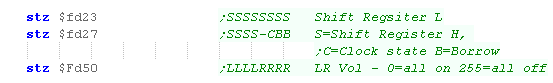
| We're ready, but we need to reset a few other settings to
prepare the sound chip. ($FD21,$FD23,$FD27,$FD50) We don't need any special settings for these to make our basic sounds |
 |
| We need to reset the 'audio output' of the channel - this is the current value the sound channel is playing - we reset it to $80 to make it silent | 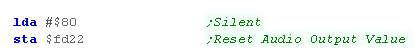 |
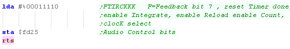
| Finally we need to set the Audio control bits Our sound will now play! |
 |

Sfx with Chibisound!
| These tutorials use a sound 'driver' called
ChibiSound, Chibisound uses a single byte parameter in the Accumulator, and provides 64 different pitches, in low or high volume with either tones or noise. Sending a value of 0 mutes sound, all other values make a tone... Chibisound is intended to make it simple to have SFX in multiplatform games and was used in Grime Z80 and Grime 6502 |
|
Sound Ports on the PC Engine
The PC engine has sound 10 registers
controlling 6 channels - all 6 are digital (they use 32 bytes of 5 bit
wave data), but only 5 and 6 can make noise
Before we write our wave data we need to
set Bit 7 of Reg 4 to 0... then we write 32 bytes to $0806 (only 5 bits
per sample!)
| Reg | Address | Meaning | Channels | 7
|
6
|
5
|
4
|
3
|
2
|
1
|
0
|
Bit Meaning |
| 0 | $0800 | Channel Select | All | - | - | - | - | - | C | C | C | Channel Select |
| 1 | $0801 | Main Amplitude Level | All | L | L | L | L | R | R | R | R | L/R Volume |
| 2 | $0802 | Frequency L | 0-5 | L | L | L | L | L | L | L | L | Frequency botttom 8 bits |
| 3 | $0803 | Frequency H | 0-5 | - | - | - | - | H | H | H | H | Frequency top 4 bits |
| 4 | $0804 | Channel On/Write | 0-5 | E | D | - | V | V | V | V | V | Enable (play)/write data... Direct digitaldata� channel Volume |
| 5 | $0805 | LR Volume | 0-5 | L | L | L | L | R | R | R | R | L/R Volume |
| 6 | $0806 | Waveform Data | 0-5 | - | - | - | W | W | W | W | W | Wave data (write 32 times) |
| 7 | $0807 | Noise Enable | 4-5 | E | - | - | N | N | N | N | N | Enable noise� Noise freq (Chn 4/5 only) |
| 8 | $0808 | LFO Freq | All | F | F | F | F | F | F | F | F | LFO Frequency |
| 9 | $0809 | LFO Control | All | T | - | - | - | - | - | C | C | LFO Trigger� Control |
Writing Chibi Sound!
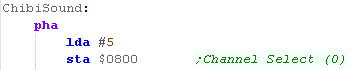
| Starting ChibiSound, we first want to select a channel... we
need a channel that can make noise, so we'll use Channel 5 |
 |
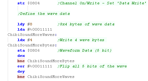
| We want to write data to the wave sample, so we need to set
bit 7 of $0804 to zero, To do this quickly, we'll use the HuC6280 command STZ to set $0804 to zero - this also turns OFF the channel Now we want to write the wave data for a square wave, because we can only use 5 bit samples, we need to write 4 bytes of %00011111 and then 4 of %000000000, We repeat this 8 times to make the 32 bit sample |
 |
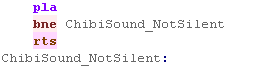
| If A=0 then we want to mute the sound, we actually turned the
channel off with our last command, so we can just return |
 |
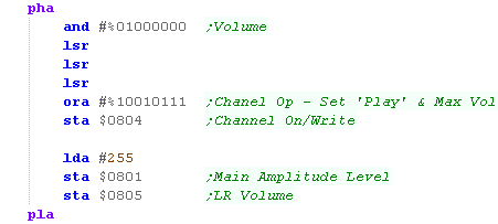
| We now need to turn on the channel, and set a proper volume,
Chibisound only has one bit for volume, we shift this into bit 4
of the volume setting (setting all the other volume bits to
1)... We also need to set the top bit to turn the channel on. We then also set the main and LR volume to max |
 |
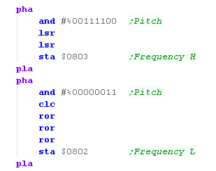
| OK, we now need to set the pitch of the sound... We have 6 bits, but we split them up, so we can best use them for the PC Engine's 12 bit frequency definition. |
 |
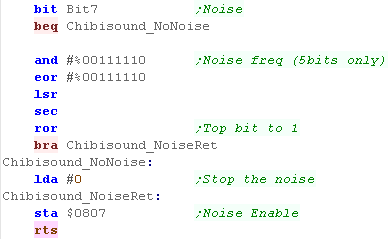
| Finally, we check our noise bit (bit 7), If the noise bit is 0, we need to turn off the noise (by writing zero)... If it's not, then we need to convert our 6 bit frequency for the 5 bit noise setting, and turn noise on. We're finally done! |
 |
| Making a
beep is a bit of a pain on the PC-Engine, but it's 6 digital
sound channels give it powerful sound potential, but it's
easier to understand than the Lynx, and far easier than the
horrible complexity of the SNES (which is comparable in other
technical capabilities) |
|
Sound Ports on the Nes/Famicom
The NES and Famicom use a set of memory
mapped registers to configure the 5 different sound channels, we just
write byte data to the ports to configure the ports (though we cannot read
back)
| Address | Purpose | Bits | Details |
| 4000h | APU Channel 1 (Rectangle) Volume/Decay (W) | CCLEVVVV | Volume, Envelope, Length counter,duty Cycle |
| 4001h | APU Channel 1 (Rectangle) Sweep (W) | EUUUDSSS | Sweep, Direction,Update rate, Enabled |
| 4002h | APU Channel 1 (Rectangle) Frequency (W) | LLLLLLLL | frequency L byte |
| 4003h | APU Channel 1 (Rectangle) Length (W) | CCCCCHHH | frequency H byte, length Counter load register |
| 4004h | APU Channel 2 (Rectangle) Volume/Decay (W) | CCLEVVVV | Volume, Envelope, Length counter,duty Cycle |
| 4005h | APU Channel 2 (Rectangle) Sweep (W) | EUUUDSSS | Sweep, Direction,Update rate, Enabled |
| 4006h | APU Channel 2 (Rectangle) Frequency (W) | LLLLLLLL | frequency L byte |
| 4007h | APU Channel 2 (Rectangle) Length (W) | CCCCCHHH | frequency H byte, length Counter load register |
| 4008h | APU Channel 3 (Triangle) Linear Counter (W) | CLLLLLLL | Clock disable start, Linear count load reg |
| 4009h | APU Channel 3 (Triangle) N/A (-) | -------- | unused |
| 400Ah | APU Channel 3 (Triangle) Frequency (W) | LLLLLLLL | frequency L byte |
| 400Bh | APU Channel 3 (Triangle) Length (W) | CCCCCHHH | frequency H byte, length Counter load register |
| 400Ch | APU Channel 4 (Noise) Volume/Decay (W) | CCLEVVVV | Volume, Envelope, Length counter,duty Cycle |
| 400Dh | APU Channel 4 (Noise) N/A (-) | -------- | unused |
| 400Eh | APU Channel 4 (Noise) Frequency (W) | LLLLLLLL | frequency L byte |
| 400Fh | APU Channel 4 (Noise) Length (W) | CCCCCHHH | frequency H byte, length Counter load register |
| 4010h | APU Channel 5 (DMC) Play mode and DMA frequency (W) | IL�FFFF | Irq enable, Loop, Frequency |
| 4011h | APU Channel 5 (DMC) Delta counter load register (W) | -DDDDDDD | Delta Counter or 7bit PCM Data |
| 4012h | APU Channel 5 (DMC) Address load register (W) | AAAAAAAA | Address = $C000+(A*$40) |
| 4013h | APU Channel 5 (DMC) Length register (W) | LLLLLLLLL | Length = (L*$10)+1 Bytes |
| 4015h | DMC/IRQ/length counter status/Sound channel enable register (RW) | DF-54321 | Dmc irq status/ Frame irq status Channel 12345 on |
Writing Chibi Sound!
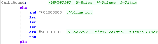
| Lets Write the Chibisound driver... First we need to calculate the volume, we only have one bit of volume definition passed to chibisound, so we'll move it to bit 4, and set the other 3 volume bits to zero, We also need to set bits 4 and 5, to disable the Clock and Envelope of the channel, however where we need to write this depends on if we're making a tone or noise, so we'll store it into X for later |
 |
| Now we've popped A, we have the flags updated, so we'll check
if A is zero, if it is we need to silence the channels We do this by writing zero to $4015... which will turn off all the channels! |
  |
| We're going to test bit 7 of the accumulator - if it's 1, then we need to play a noise sample | 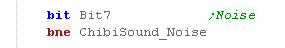 |
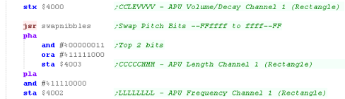
| If we're not making a noise, then we need to store the
volume we calculated to $4000 Now we need to put our 6 bits of pitch in the Accumulator into $4003 and $4002... We flip the nibbles, and rotate the bits around into the best positions for the sound. |
 |
| Now we need to turn channel 0 on so we can hear our noise... we do this by setting bit 0 to one, and writing to $4015 | 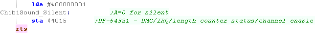 |
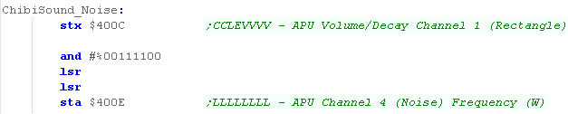
| If we ARE making a noise, we need to store the volume
to $400C instead We now need to load the noise frequency into $400E, however we can only really use 4 of the bits of our 6 bit frequency, as we need to move them to the 4 least significant bits to get a noise type that matches our other systems. |
 |
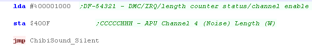
| Next we need to set the bottom 3 bits of $400F to zero - the
top 5 bits are the counter (but we disabled this to our write to
$400C) we also need to turn on bit 4 of $4015 to turn on the sound channel, but we can load A once, and use the same value for both purposes We then jump to the 'ChibiSound_Silent' label, to write to $4015 and return |
 |
| In this way we can at least manage the basics of sound on the Nes, of course the NES has more capabilities - like triangle waves, and the potential for digital sound... but if you want to use those, you'll have to figure them out yourself! | |
SPC700 Assembly
| The SNES SPC700 sound chip uses it's own assembly language,
it's syntax is similar to z80, but it's registers are more like
the 6502! We're going to write a simple
program in these tutorials, but we're not going to cover the
whole instruction set... please see the SFC
development wiki which already covers this in far more
detail than I ever can.
In these tutorials we use VASM
for assembly, but VASM doesn't support the SPC700 instruction
set - if we were writing a complex program we could use a different
assembler, but as we're only doing the basics, we'll
define macros to simulate the SPC700 commands we need.
|
 |
|
If you want
to make something more complex, you'll probably want to use a
real SPC700 assembler, then again, it would probably be best
to find some existing music playing software for the SPC700
and use that instead! |
Communicating with the
SPC700
The SPC700 has it's own memory with a zero
page (direct page) - 4 bytes of this memory 'link' to 4 bytes on the
regular 65816 processor - these are our way of instructing (and
transferring data) to the SPC700
| 65816
side |
SPC700 side |
| $2140 | $00F4 |
| $2141 | $00F5 |
| $2142 | $00F6 |
| $2143 | $00F7 |
The important thing to remember with the
SPC700 ports is R and W are separate
The 65816 can write $66 to $2140, but that doesn't mean that value will be read back by the 65816!... $2140 will only contain $66 if the SPC700 writes $66 value to its port $00F4 ($00F4/$2140 are a pair)
That's how wait loops may write a value to the port, and wait until the same value is read back as a sync timer
The SPC700 Memory Map
The SPC700 has 64k of ram, there are two
registers at $00F2 and $00F3 to access the sound registers (well look
at them later) and 4 registers to talk to the 65816
| Start |
End | Purpose |
| 0000 | 00EF
|
Zero Page / Direct Page |
| 00F0 | 00F0 | Unused |
| 00F1 | 00F1 | Control Port (Timers & reset) |
| 00F2 | 00F2 | Sound Register Select |
| 00F3 | 00F3 | Sound Register Value |
| 00F4 | 00F4 | Link to 65816 address $2140 |
| 00F5 | 00F5 | Link to 65816 address $2141 |
| 00F6 | 00F6 | Link to 65816 address $2142 |
| 00F7 | 00F7 | Link to 65816 address $2143 |
| 0100 | 01FF | Stack |
| 0200 | FFBF | RAM |
| FFC0 | FFFF | ROM |
Waiting for the
initialization of the firmware.
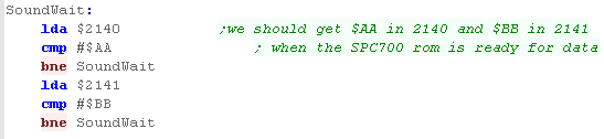
When the snes turns on, We need to wait
for the SPC700 to be ready, we need to check for 2 values
1. Wait for $2140 to return $AA
2. Wait for $2141 to return $BB
Sending data to the
SPC700
When the system boots the firmware of the
SPC700 at $FFC0 this will start and wait for data from the 65816.. to
send data to the SPC700 ram we use the following procedure.
1. Store the Destination address (in SPC700
ram) into $2142/3
2. Store a nonzero value in $2141
3. Write $CC to $2140 to tell the system
we're ready
4. Wait for $2140 to return $CC
5. Write the first byte to #2141
6. Write the bytenumber (0) to $2140
7. Wait for $2140 to return the bytenumber
(0)
8. Write the next byte to $2141
9. Increase the bytenumber in $2140
Executing the data we transferred10. Wait for $2140 to return the
bytenumber
11. repeat stage 8
1. Write $0 to $2141
2. Write the address (in SPC700 ram) to call
into $2142/3
3. Read the value in $2140, add 2, and write
the value back to $2140
4. Wait for $2140 to return the same value
Coding the transfer
routine
| First we need to wait for the SPC700 to be ready, It should return $AA and $BB |
 |
| We write the destination address (in SPC700 ram) to $2142/3 Now we write 1 to $3141, and $CC to $2140 We now wait for $2140 to return $CC... REMEMBER: Just because we wrote $CC to $2140 doesn't mean we'll read it back - not until the SPC700 writes $CC there! |
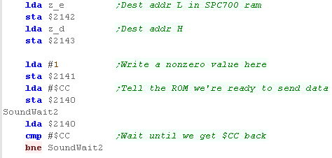 |
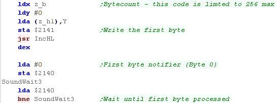
| We need to write the first byte from HL to #2141 We also init the byte count by writing 0 to $2140 and waiting for the SPC700 to return it. |
 |
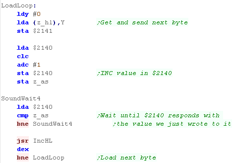
| We now repeat the procedure for all the bytes we want to send, Writing each to #2141, then updating the bytecount in $2140, and waiting for $2140 to update. We're using X as our loopcounter, and we repeat until it reaches zero - so this function is limited to 256 bytes |
 |
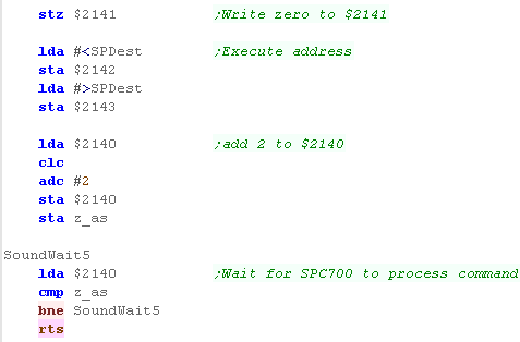
| Our program is copied, but now we need to call our
program, We do this by writing the call address to $2142/3 We add 2 to whatever is in $2140, and write it back, and then wait for the SPC700 to return the same value from $2140 The address we passed in $2142/3 will be now running on the SPC700! |
 |
|
We can transfer more data
later, but we'll need to get the SPC700 to call the firmware at
$FFC0 somehow... The code we'll look at in moment can do this - and we use it to write our program code in one transfer, then the samples as a second. |
Coding for the SPC700
We want to be able to control the sound
chip's register from the 65816 easilly, to do this we're going create a
program for the SPC700, which will write data from the accessible ports
straight to the registers... here's how we'll use the ports
| Port SPC700 / 65816 | Purpose |
| $00F4 / $2140 | if command 3... Reg num |
| $00F5 / $2141 | if command 3... Reg val |
| $00F6 / $2142 | Command... 3=SetReg / 2=restart ROM data transfer |
| $00F7 / $2143 | Sync... Read the value in this port, and write it back to the SPC700 to do a command.. then wait until the read data changes to know the command was processed |
| We're going to define two memory addresses... SPDest is the address in SPC700 ram that our program will end up ($0300) SoundKeyAddr is a byte in SPC700 ram we'll use to hold a temp byte for the pause routine. ($F000) |
 |
| The main loop is simple, we call to SoundCallPause to wait for a
'sync' on $00F7 Then we read in the command from $00F6, depending on what it is, we process it. Then we need to clear the command with SCallResume, and finally we jump back to the main loop |
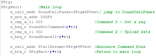 |
| Note, Because this code will be copied to a different processor,
we need to recalculate destination addresses for CALL (absolute)
and BRAnch (relative) for a CALL (absolute), we calculate the Destination Label minus the start of the code (on the 65816) plus the destination address of the code (on the SPC700) for a BRAnch (relative), we calculate the Destination Label minus the current address of the running code (*+1) |
Fixing addresses for Branches and Calls: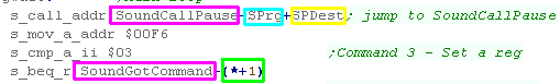 |
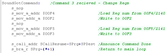
| When we get a Command 3 - we need to write data to the sound
registers... The Sound Register number is read from $00F4, and written to the selection port at $00F2 The new Sound Register value is read from $00F5, and written to the selection port at $00F3 The sound register has now been updated... we call SCallResume to tell the 65816 side that we've done what was asked. Finally we return to the main loop |
 |
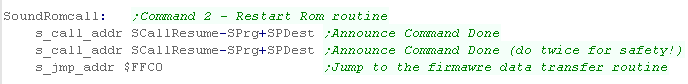
| If we get Command 2, then the 65816 wants to send more data (for
example sound samples) We announce the command was processed, then jump into the firmware at $FFC0 - which will take things from there! |
 |
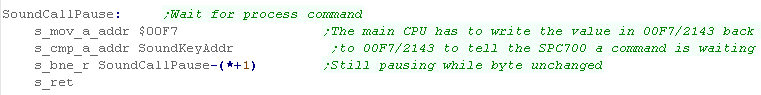
| the SoundCallPause waits until the Sync at $00F7 is sent... this
happens when the 65816 writes the sent value back to
$00F7/$2143... the temp value at 'SoundKeyAddr' ($F000) is used to store the expected value |
 |
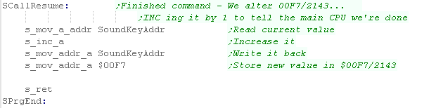
| Finally we need a 'finishing' command -this updates the 'Sync'
value, and writes it back, this is what we execute when we've
finished a command... Our program is done! |
 |
Using our code to control
SPC700 registers from the 65816
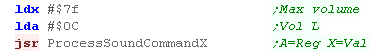
| When we want to set a registers, we can load X with the new
Value, and A with the Register number then we call call ProcessSoundCOmmandX to do the work! |
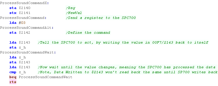
 |
| We write the new value to $2141, and the register to $2140 now we send 'Command 3' to $2142 to start the routine we just wrote. Next we update the Sync byte - telling the SPC700 to get to work, Finally we pause until the sync byte changes - when it does the SPC700 has finished the job! |
 |
|
This isn't
really a smart way to use the SPC700 - really we'd want a music
player on there, so we could leave it playing music by itself
without bothering the main CPU, But in this example, we want something 'simple' so we can control the registers and learn how they work. |
SPC700 Sound Registers
The driver we wrote last time is handling
setting the registers, but we still need to know what the actual
registers do, so we know what to change, here's the register list in
full!
| Address | Register | Description | Bits | Meaning |
| c0 | VOL (L) | Left Volume | -VVVVVVV | Volume |
| c1 | VOL (R) | Right Volume | -VVVVVVV | Volume |
| c2 | P (L) | Pitch L | PPPPPPPP | Pitch |
| c3 | P (H) | Pitch H | --PPPPPP | Pitch |
| c4 | SRCN | Source number (references the source directory) | SSSSSSSS | Source |
| c5 | ADSR (1) | If bit7 is set, ADSR is enabled. If cleared GAIN is used. | EDDDAAAA | Enable, Dr, Ar |
| c6 | ADSR (2) | These two registers control the ADSR envelope. | LLLRRRRR | sL,sR |
| c7 | GAIN | This register provides function for software envelopes. | GGGGGGGG | G=Envelope bits |
| c8 | -ENVX | (auto updated) Readable current Envelope Value | 0VVVVVVV | Value |
| c9 | -OUTX | (auto updated) Readable current Waveform Value | SVVVVVVV | Signed Value |
| 0C | MVOL (L) | Main Volume Left | -VVVVVVV | Volume |
| 1C | MVOL (R) | Main Volume Right | -VVVVVVV | Volume |
| 2C | EVOL (L) | Echo Volume Left | -VVVVVVV | Volume |
| 3C | EVOL (R) | Echo Volume Right | -VVVVVVV | Volume |
| 4C | KON | Key On | CCCCCCCC | Channel |
| 5C | KOF | Key Off | CCCCCCCC | Channel |
| 6C | FLG | DSP Flags. (used for MUTE,ECHO,RESET,NOISE CLOCK) | RMENNNNN | Reset
(0=off) Mute (0=off) Echo (1=0ff) Noise clock |
| 7C | -ENDX | (auto updated) read to see if channel done | CCCCCCCC | Channel |
| 0D | EFB | Echo Feedback | SFFFFFFF | Signed Feedback |
| 2D | PMON | Pitch modulation | CCCCCCC- | Channel (1-7) |
| 3D | NON | Noise enable | CCCCCCCC | Channel |
| 4D | EON | Echo enable | CCCCCCCC | Channel |
| 5D | DIR | Offset of source directory (DIR*100h = memory offset) | OOOOOOOO | Offset $oo00 |
| 6D | ESA | Echo buffer start offset (ESA*100h = memory offset) | OOOOOOOO | Offset $oo00 |
| 7D | EDL | Echo delay, 4-bits, higher values require more memory. | ----EEEE | Echo delay |
| fF | COEF | 8-tap FIR Filter coefficients | SCCCCCCC | Signed Coeficcient |
| c = Channel 0-7� f = filter coefficient 0-7 | ||||
Sfx with Chibisound!
| These tutorials use a sound 'driver' called
ChibiSound, Chibisound uses a single byte parameter in the Accumulator, and provides 64 different pitches, in low or high volume with either tones or noise. Sending a value of 0 mutes sound, all other values make a tone... Chibisound is intended to make it simple to have SFX in multiplatform games and was used in Grime Z80 and Grime 6502 |
|
Sound Samples
| Sound samples must also be held in SPC700 ram... Pointers to Sound samples are stored in a single block.. this block must be byte alined, and has 256 sound definitions - each of which contains 2 pointers... one for the start of the sample, and one for the loop For example, take the example definition, this will be loaded into SPC700 ram at $300... we would tell the sound chip to use $03 as the memory position using the "DIR" sound register $5D The sound samples themselves are made up of 9 byte chunks, the first byte is a header, and the other 16 nibbles are the sound data... the final sample in the sound should have the End bit set in the header, and the Loop bit if you wish |
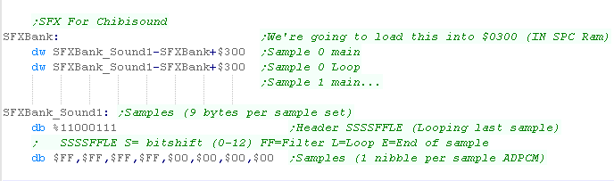 |
| The sound
sample format is pretty complex, it's effectively a kind of
ADPCM, you'll probably want to find a converter and convert
some WAV samples into the correct format for the SNES. The sample we use here is just a simple test so we can here the SPC700 actually do something! |
|
Writing ChibiSound
| Exclusively on the Snes we're going to have an INIT routine,
this is because we need to transfer the program to the SPC700
to handle that side of things, At the same time, we'll set up the default volume, pointer to our sound sample, and a few other values. Now they're set up We won't need to set these values again! |
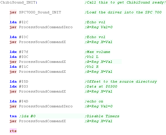 |
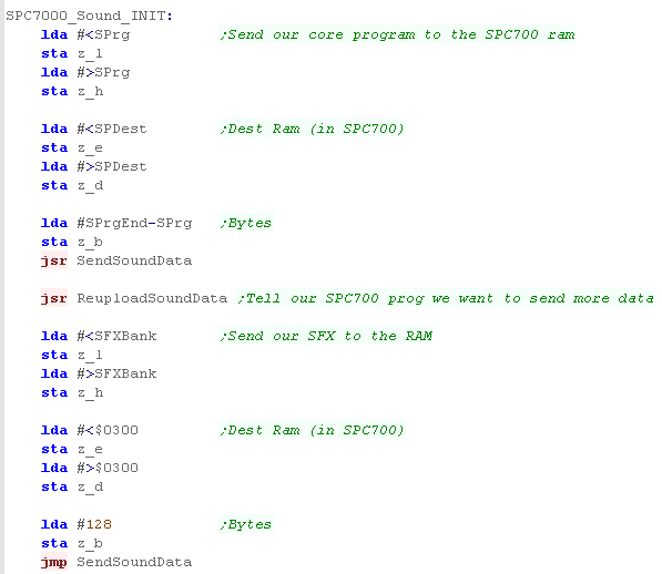
| The init routine to transfer the data to the SPC700 has two
parts, The first copies the program code to $0200 The Second Copies the sound sample(s) to $0300 - this is the square wave we'll use for beeps! |
 |
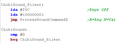
| The First thing ChibiSound does is check if the sound needs
to be turned off.. If it does we use 'Keys off' to turn off Channel 0... this tells the SPC700 to stop channel 0 |
 |
| Before we start, we need to reset some settings... we set 'Keys On' to zero so no keys are pressed, and the 'Noise Clock' bits to 1 | 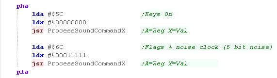 |
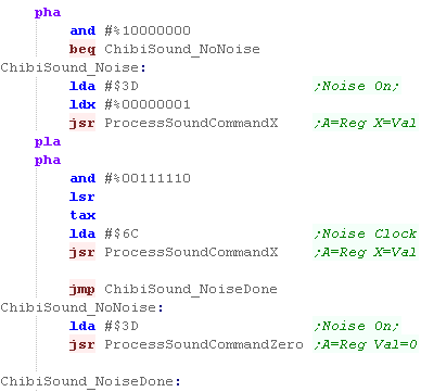
| We're going to check if the noise needs turning on (Bit 7 of
the accumulator when chibisound is called) If we need noise, then we turn noise on for Channel 0, we also need to set the noise clock (pitch of the noise)... we have 6 bits of frequency in the accumulator, but we can only use 5. If the noise is off, then we turn 'noise on' to zero. |
 |
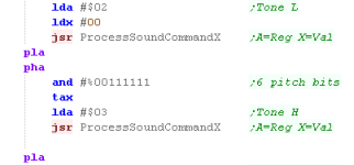
| Ok, we're going to set the pitch of the tone, the SNES uses
14 tone bits (in registers $02,$03 for Channel 0) We only have 6 bits - so the bottom 8 (in $02) will be all zero, and we'll set out 6 bits in reg 03. |
 |
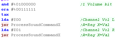
| Ok, on to volume - the SNES uses 7 bits - we have just one
volume bit, so we'll just set the other six to 1 to make a 'central' channel, we set both Left (reg $00) and Right ($01) to the same volume |
 |
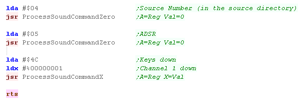
| Our sound is pretty much ready, but there's a few last
setting to set... First we want to set the source sample (Reg $04) - we're using Sample 0 in our sound bank. Next we want to turn of 'ADSR' (Reg $05 - envelopes) we just want a simple tone - so we set this to 0 Finally we want to start the tone of Channel 0 - so we set Bit 0 of 'Keys down' (Reg $4C) to 1 Phew! after all that, we're done! |
 |
|
We've made a beep on the SNES - and it's
only taken about 200 lines of code! Of course, the SNES sound chip is really designed for making music, using digital sound samples of instruments, but if you want to try to do that, you're on your own! There are music players available for the snes - so you don't really need to write one, but for these tutorials, we always try to do things ourselves! |

VIC 20 Sound ports
There are 3 sound channels for the 3 different frequencies, one for
random noise, and a volume setting...
As well as volume The top 4 bits of the $900E also handles color
| Address | Meaning | Bits | Details |
| $900A | Frequency for oscillator 1 (Bass) | OFFFFFFF | O=On
F=Frequency |
| $900B | Frequency for oscillator 2 (medium) | OFFFFFFF | O=On F=Frequency |
| $900C | Frequency for oscillator 3 (high freq) | OFFFFFFF | O=On F=Frequency |
| $900D | Frequency of noise source | OFFFFFFF | O=On F=Frequency |
| $900E | Volume of all sound / Auxiliary color information | CCCCVVVV | V=Volume C=Aux color |
Sfx with Chibisound!
| These tutorials use a sound 'driver' called
ChibiSound, Chibisound uses a single byte parameter in the Accumulator, and provides 64 different pitches, in low or high volume with either tones or noise. Sending a value of 0 mutes sound, all other values make a tone... Chibisound is intended to make it simple to have SFX in multiplatform games and was used in Grime Z80 and Grime 6502 |
|
Writing Chibisound
| When Chibisound starts, we have our byte in the
Accumulator, we need to back it up into the stack during each
stage to keep it intact, First we're going to work out the pitch, but we don't know where we want to store it until we decide whether we make Noise or Tone sounds. We calculate the tone from the 6 bits, and store it in Y - we store a zero in X to silence the other channel we don't need |
 |
| When we get the Accumulator back to the stack, the flags will
be updated, if A=0 we now jump to the volume routine to silence the sound chip - we'll see this later |
 |
| Depending on our Noise bit, we either make a Tone using port
$900D, or a noise with $900D... we need to write a zero to the
one we're not using. To do this we use the calculated pitch value in Y, and the zero in X to do the job, but we'll flip them around if the noise bit is set |
 |
| Our last task is to set the volume, We only have one volume
bit in the Accumulator so set the other 3 volume bits to 1. We need to load this into $900E to set the volume, but the top nibble of this register handles the Aux color, First we load this, and keep it in zeropage entry z_as, then we OR in our new volume, and store the result back to $900E Note this code also handles the 'Mute' jump we wrote earlier. |
 |
| We've used 2
of the 4 channels, but the other 2 are basically the same,
they just handle different sound pitches. We can change the pitch of the function by using $900A or $900C instead of $9000B in our code. |
|

SID 6581 sound chip
The SID chip uses memory addresses $D400-$D41C
The SID chip uses memory addresses $D400-$D41C
| Address | Description | Bits | Meaning |
| $D400 | Voice #1 frequency L | LLLLLLLL | |
| $D401 | Voice #1 frequency H | HHHHHHHH | Higher values=higher pitch |
| $D402 | Voice #1 pulse width L | LLLLLLLL | |
| $D403 | Voice #1 pulse width H | ----HHHH | |
| $D404 | Voice #1 control register | NPST-RSG | Noise /
Pulse / Sawtooth / Triangle / - test / Ring mod / Sync / Gate
(Turn on) |
| $D405 | Voice #1 Attack and Decay length | AAAADDDD | Atack / Decay |
| $D406 | Voice #1 Sustain volume and Release length. | SSSSRRRR | Sustain / Release |
| $D407 | Voice #2 frequency L | LLLLLLLL | |
| $D408 | Voice #2 frequency H | HHHHHHHH | Higher values=higher pitch |
| $D409 | Voice #2 pulse width L | LLLLLLLL | |
| $D40A | Voice #2 pulse width H | ----HHHH | |
| $D40B | Voice #2 control register | NPST-RSG | Noise / Pulse / Sawtooth / Triangle / - test / Ring mod / Sync / Gate (Turn on) |
| $D40C | Voice #2 Attack and Decay length | AAAADDDD | Atack / Decay |
| $D40D | Voice #2 Sustain volume and Release length. | SSSSRRRR | Sustain / Release |
| $D40E | Voice #3 frequency L | LLLLLLLL | |
| $D40F | Voice #3 frequency H | HHHHHHHH | Higher values=higher pitch |
| $D410 | Voice #3 pulse width L | LLLLLLLL | |
| $D411 | Voice #3 pulse width H | ----HHHH | |
| $D412 | Voice #3 control register. | NPST-RSG | Noise / Pulse / Sawtooth / Triangle / - test / Ring mod / Sync / Gate (Turn on) |
| $D413 | Voice #3 Attack and Decay length. | AAAADDDD | Atack / Decay |
| $D414 | Voice #3 Sustain volume and Release length. | SSSSRRRR | Sustain / Release |
| $D415 | Filter cut off frequency L | -----LLL | |
| $D416 | Filter cut off frequency H | HHHHHHHH | |
| $D417 | Filter control | RRRREVVV | R=Resonance / External / V= Voice 3-1 |
| $D418 | Volume and filter modes | MHBLVVVV | Mute3 / Highpass / Bandpass / Lowpass / Volume (0=silent) |
| $D41B | Voice #3 waveform output. (Read only) | DDDDDDDD | |
| $D41C | Voice #3 ADSR output. (Read only) | DDDDDDDD |
Sfx with Chibisound!
| These tutorials use a sound 'driver' called
ChibiSound, Chibisound uses a single byte parameter in the Accumulator, and provides 64 different pitches, in low or high volume with either tones or noise. Sending a value of 0 mutes sound, all other values make a tone... Chibisound is intended to make it simple to have SFX in multiplatform games and was used in Grime Z80 and Grime 6502 |
|
Writing Chibisound
| When Chibisound starts, we need to back up the Accumulator at
each stage to keep it's value for the next calculation - we do
this by pushing it onto the stack. We're going to use Voice #1 for all our sounds, and first we'll set the pitch with our 6 bits, we write them to address $D401 to set the pitch |
 |
| Now we'll pull the Accumulator off the stack, this will also update the flags, we'll use this to check if the Accumulator is zero, if it is, we jump to the label 'ChibiSouns_Silent - which will set the volume to zero via $D418 |   |
| Next we're going to check the Noise bit... if it's set, we
need to set bit 7 of $D404.... if not we need to make a tone, by
setting Bit 6 Either way, we also need to set Bit 0 (the 'Gate') this turns the sound on |
 |
| We need to set some of the other registers to make our tone,
We need to set $D402 and $D405 to zero, but we also want
to set $D400,$D403 and $D406 to 255... We start by setting X to zero, and writing it to $D402/5... then we DEcrement X, and write 255 to $D400/3/6 This sets up the tone we want. |
 |
| Finally, we need to set the volume, the SID uses a 4 bit
volume, but we only have 1 bit in the Accumulator, we set the
other bits to 1, and write the value to $D418 This is also where the 'Silent' jump we made earlier ends up. |
 |
|
We've only used one
Voice in this example, but we can use the others in the same
way... we can also change the value we write to $D404, #%01000000 will be a Pulse, #%00100000 is Sawtooth, and #%00010000 is a Triangle sound. Attack and Decay can also be changed to alter the way the sound changes over time. |
| View Options |
| Default Dark |
| Simple (Hide this menu) |
| Print Mode (white background) |
| Top Menu |
| ***Main Menu*** |
| Youtube channel |
| Patreon |
| Introduction to Assembly (Basics for absolute beginners) |
| Amazon Affiliate Link |
| AkuSprite Editor |
| ChibiTracker |
| Dec/Bin/Hex/Oct/Ascii Table |
| Alt Tech |
| Archive.org |
| Bitchute |
| Odysee |
| Rumble |
| DailyMotion |
| Please note: I wlll upload more content to these alt platforms based on the views they bring in |
| 68000 Content |
| ***68000 Tutorial List*** |
Learn 68000 Assembly  |
| Hello World Series |
| Platform Specific Series |
| Simple Samples |
| Grime 68000 |
| 68000 Downloads |
| 68000 Cheatsheet |
| Sources.7z |
| DevTools kit |
| 68000 Platforms |
| Amiga 500 |
| Atari ST |
| Neo Geo |
| Sega Genesis / Mega Drive |
| Sinclair QL |
| X68000 (Sharp x68k) |
| 8086 Content |
| Learn 8086 Assembly |
| Platform Specific Series |
| Hello World Series |
| Simple Samples |
| 8086 Downloads |
| 8086 Cheatsheet |
| Sources.7z |
| DevTools kit |
| 8086 Platforms |
| Wonderswan |
| MsDos |
| ARM Content |
| Learn ARM Assembly |
| Learn ARM Thumb Assembly |
| Platform Specific Series |
| Hello World |
| Simple Samples |
| ARM Downloads |
| ARM Cheatsheet |
| Sources.7z |
| DevTools kit |
| ARM Platforms |
| Gameboy Advance |
| Nintendo DS |
| Risc Os |
| Risc-V Content |
| Learn Risc-V Assembly |
| Risc-V Downloads |
| Risc-V Cheatsheet |
| Sources.7z |
| DevTools kit |
| MIPS Content |
| Learn Risc-V Assembly |
| Platform Specific Series |
| Hello World |
| Simple Samples |
| MIPS Downloads |
| MIPS Cheatsheet |
| Sources.7z |
| DevTools kit |
| MIPS Platforms |
| Playstation |
| N64 |
| PDP-11 Content |
| Learn PDP-11 Assembly |
| Platform Specific Series |
| Simple Samples |
| PDP-11 Downloads |
| PDP-11 Cheatsheet |
| Sources.7z |
| DevTools kit |
| PDP-11 Platforms |
| PDP-11 |
| UKNC |
| TMS9900 Content |
| Learn TMS9900 Assembly |
| Platform Specific Series |
| Hello World |
| TMS9900 Downloads |
| TMS9900 Cheatsheet |
| Sources.7z |
| DevTools kit |
| TMS9900 Platforms |
| Ti 99 |
| 6809 Content |
| Learn 6809 Assembly |
| Learn 6309 Assembly |
| Platform Specific Series |
| Hello World Series |
| Simple Samples |
| 6809 Downloads |
| 6809/6309 Cheatsheet |
| Sources.7z |
| DevTools kit |
| 6809 Platforms |
| Dragon 32/Tandy Coco |
| Fujitsu FM7 |
| TRS-80 Coco 3 |
| Vectrex |
| 65816 Content |
| Learn 65816 Assembly |
| Hello World |
| Simple Samples |
| 65816 Downloads |
| 65816 Cheatsheet |
| Sources.7z |
| DevTools kit |
| 65816 Platforms |
| SNES |
| eZ80 Content |
| Learn eZ80 Assembly |
| Platform Specific Series |
| eZ80 Downloads |
| eZ80 Cheatsheet |
| Sources.7z |
| DevTools kit |
| eZ80 Platforms |
| Ti84 PCE |
| IBM370 Content |
| Learn IBM370 Assembly |
| Simple Samples |
| IBM370 Downloads |
| IBM370 Cheatsheet |
| Sources.7z |
| DevTools kit |
| Super-H Content |
| Learn SH2 Assembly |
| Hello World Series |
| Simple Samples |
| SH2 Downloads |
| SH2 Cheatsheet |
| Sources.7z |
| DevTools kit |
| SH2 Platforms |
| 32x |
| Saturn |
| PowerPC Content |
| Learn PowerPC Assembly |
| Hello World Series |
| Simple Samples |
| PowerPC Downloads |
| PowerPC Cheatsheet |
| Sources.7z |
| DevTools kit |
| PowerPC Platforms |
| Gamecube |
| Work in Progress |
| ChibiAndroids |
| Misc bits |
| Ruby programming |
Buy my Assembly programming book
on Amazon in Print or Kindle!


Available worldwide!
Search 'ChibiAkumas' on
your local Amazon website!
Click here for more info!


Buy my Assembly programming book
on Amazon in Print or Kindle!
Available worldwide!
Search 'ChibiAkumas' on
your local Amazon website!
Click here for more info!
Buy my Assembly programming book
on Amazon in Print or Kindle!
Available worldwide!
Search 'ChibiAkumas' on
your local Amazon website!
Click here for more info!